DIY Ghostbusters Proton Pack Costume From a Foam Floormat
by LostWax in Craft > Costumes & Cosplay
2469 Views, 43 Favorites, 0 Comments
DIY Ghostbusters Proton Pack Costume From a Foam Floormat


Ghosts. Nobody wants them, and there’s only one way to catch them. With an unlicensed nuclear accelerator strapped to your back, of course.
Enter the proton pack
As a child of the 80’s I grew up not thinking about the Stay Puft Marshmallow Man, and I definitely knew it would be bad to cross the streams if I ever found myself behind a neutrona wand. With the cost of a decent looking proton pack being prohibitive as well as hearing tales of sore backs from heavy packs, I decided to have a go at making one myself. Out of stuff from the hardware store. and foam. a lot of foam.
As it turns out, pretty much everything I used on this build came from my local small town hardware store or the thrift shop. The main ingredients are a 4 x 8 ft, 6-7mm thick EVA foam mat, and a lot of hot glue to hold it all together. You will also want the printable pattern from my website as well!
Supplies

Supplies
- Pattern: When you print it, measure against the print guides to know the scale is correct. ** When printing, make sure scale is set to ACTUAL SIZE** Because I make my patterns to work on both A4 and U.S. letter paper, often Adobe Acrobat will try and shrink the pages a little bit.
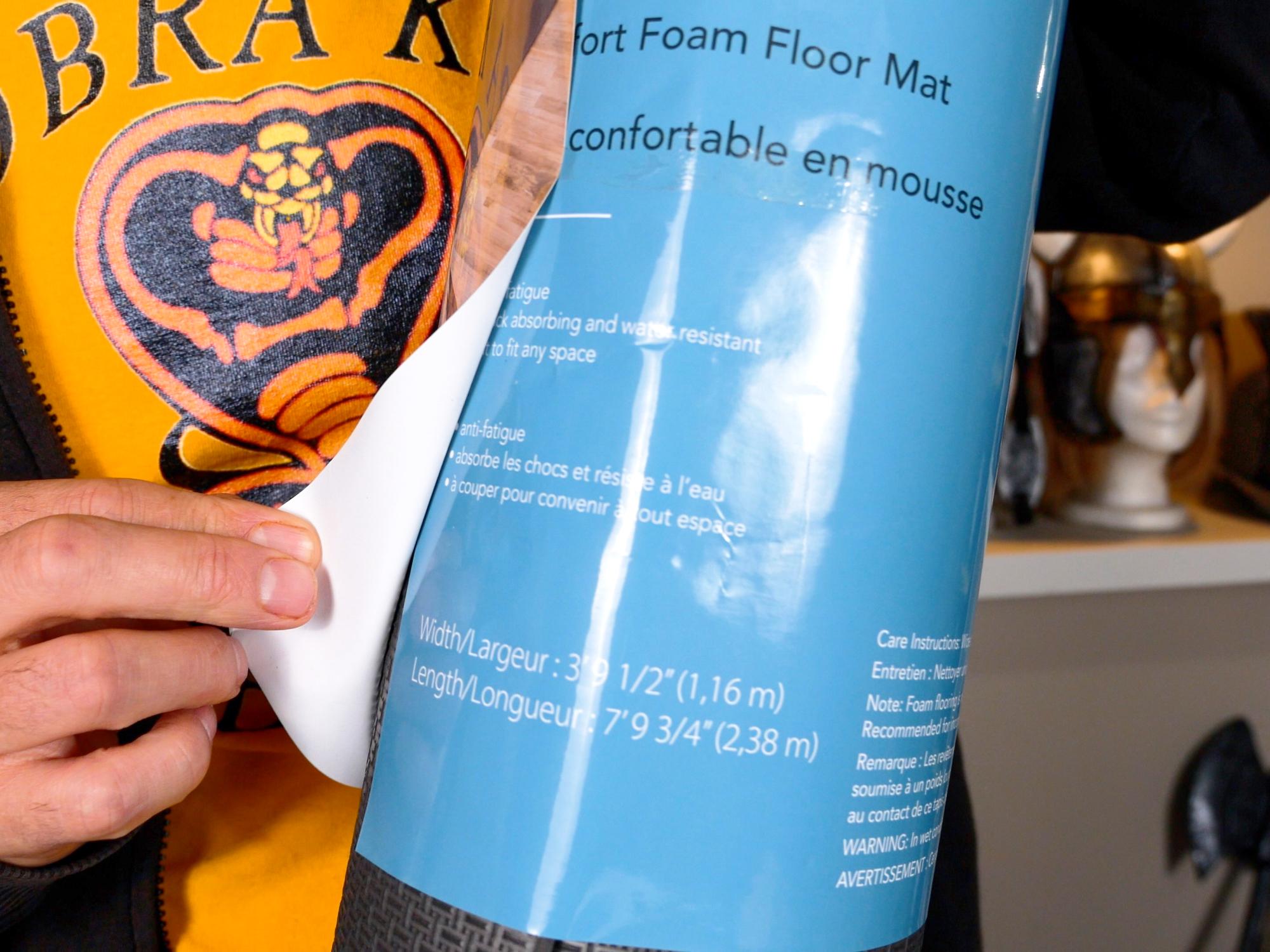
- 6-7 mm Thick Eva Foam Floor Mat: I used a mat that was 4ft x 8ft
- 2 mm Thick Eva Foam: You can often find rolls of this stuff at craft stores. A roll is handy because you can cut nice long strips from it. If you can find it in black, that’s the best - if a bit off paint gets rubbed off during use, there won’t be some random colour showing through.
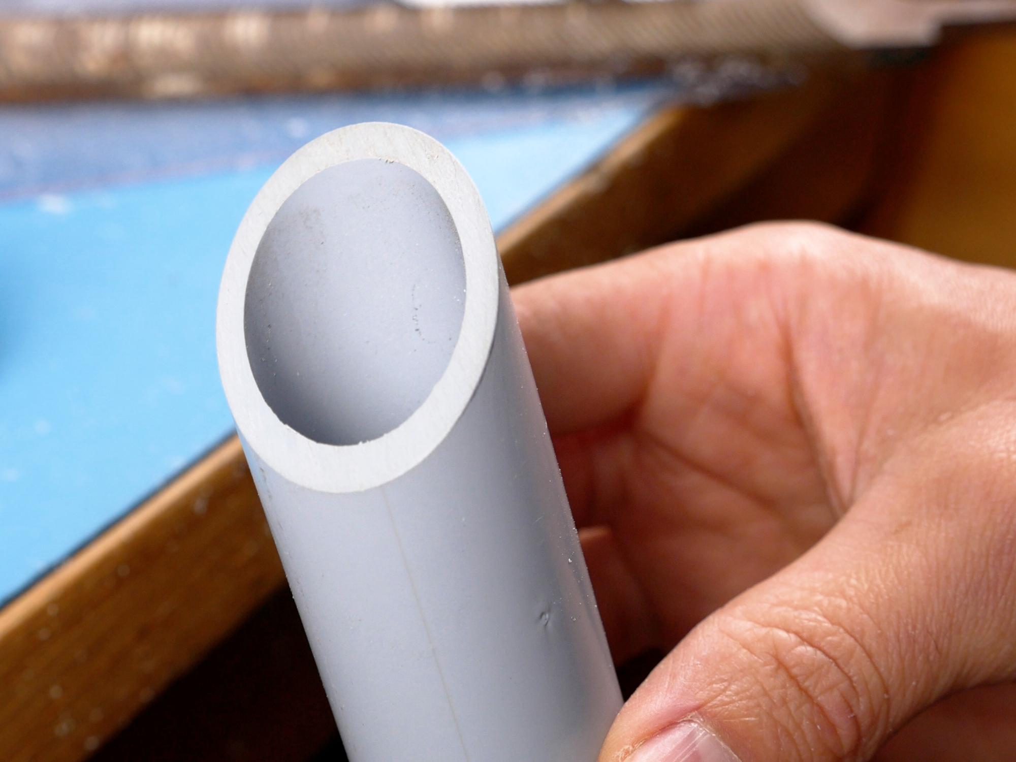
- 1 inch PVC conduit: The inside diameter is 27mm (1”), the outside diameter is 33.5mm
- 2 inch ABS Pipe: The outside diameter is 60mm
- A way to cut PVC and ABS Pipe at angles: I used a jewellers saw for the PVC and a table saw for the ABS. Other options could be a mitre saw or a handsaw used with amazing skill, or a handsaw used with poor skill and a lot of sanding.
- Paint Pen or Gel Pen: Used for any markings on the foam.
- Scissors
- Ruler
- Very Sharp Knife: If it is not really sharp you will have a terrible time when you are cutting the foam. I use a surgical scalpel or utility knife. Use a brand new blade.
- Cutting Surface: Somewhere to cut where you won’t be destroying anything.
- Hot Glue Gun: I highly suggest a glue gun that has adjustable temperature. If you use a temperature just a little bit higher than the melting point of the glue, you will have fewer burnt fingers, and not have to hold pieces together as long while they cool.
- Heat Gun or Blowdryer: Used for heating and forming the foam.
- Gluing Surface: A surface that you don’t mind getting glue on. A silicone baking sheet is great
- because hot glue doesn’t stick to it.
- Leather Punches: 4 mm and 12 mm diameter.
- Black Paint: Artists acrylics work reasonable well, though they can crack over time. If you want a really durable, long lasting finish, I would suggest using a flexible paint, such as Plaid FX paints.
- Metallic paint: I used DecoArt Americana Metallics “Silver” mixed with “Pewter” for the silver colour.
- Rubber Gloves: To wear while applying the metallic paints
- Scotch Brite abrasive pad: To roughen the plastic pipes for better paint adhesion
- Translucent Plastic: To go in front of the lights. Blue and Red are the colours you will want. I was able to use some cheap folders I found.
- Skewers: Two sizes is good.
- LED lights (optional): I got mine from an old flashlight. Also some velcro is helpful if you need to connect a battery pack
- T-Rex Tape: To make the ribbon cable
- Networking cable: used to make the ribbon cable
- Hose clamp: For holding the ribbon cable
- 5mm and 7mm cables: I used a network cable and a VGA cable I had lying around, but use whatever you have, the size isn't highly important.
- Brass Compression Fittings x 5: Used in various ways as connections to cables and hoses
Safety First


Nothing robs the joy of crafting like an unexpected trip to the hospital, so take care of yourself!
- I use hot glue in this tutorial, however I realize that many may choose to use contact cement instead. The fumes from contact cement are toxic, so, if you choose to use it, do so in a well ventilated space and wear lung protection such as a respirator.
- Whenever you heat foam (with a heatgun or blowdryer) there is potential for the foam to release harmful gases, so use a respirator and do it somewhere with good ventilation.
- Some EVA foam contains a chemical called formamide. There are some people that say there isn't enough formamide in EVA mats to be harmful, and others that say there is. Do your research and come to your own conclusions. At the least, I would say it is a good idea to open your foam mat up and let it sit in the sun for a day or two, as most of the chemical will off-gas from the foam. Or buy foam that is labelled formamide free.
- Sharp knives and hot glue can cause injury. Be sure to use in accordance with the manufacturer's instructions.
Disclaimer: If you rely on the information portrayed in these instructions, you do so at your own risk and you assume the responsibility for the results. You hereby release Lost Wax Designs from any and all actions, claims, or demands that you, your heirs, distributees, guardians, next of kin, spouse or legal representatives now have, or may have in the future, for injury, death, property damage, or any other liability that may result related to the information provided in these instructions.
Print and Assemble the Pattern

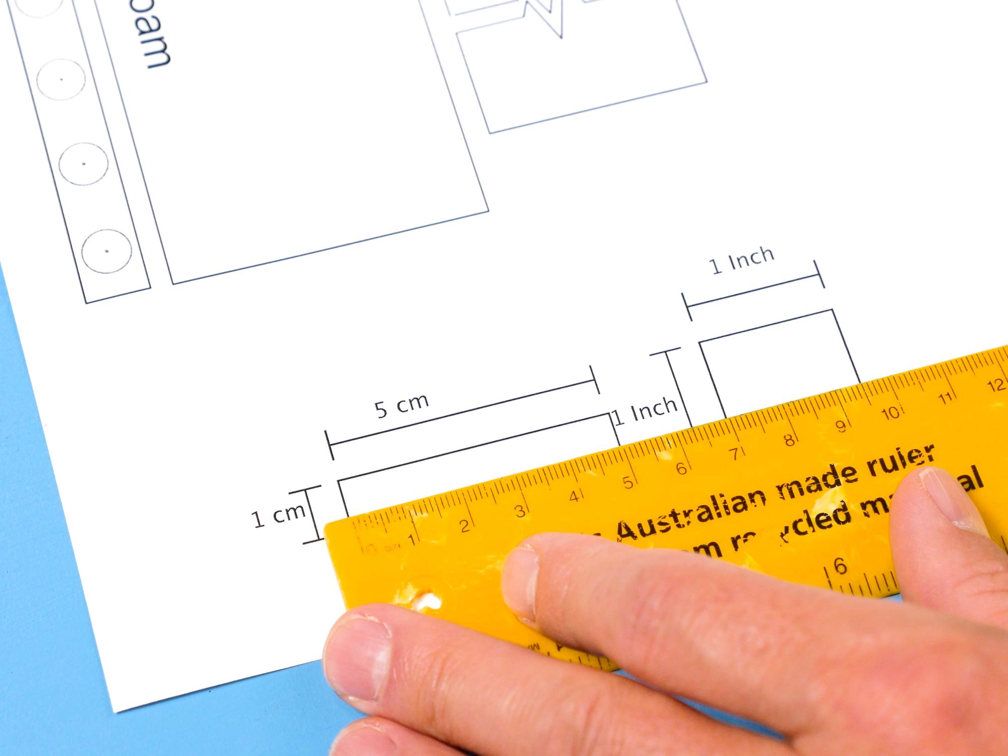
Print the pattern pages from the PDF. Make sure the scale is set to actual size or 100%. Some of the pattern pieces are larger than one sheet of paper. For these, line up the “+” marks and tape the sheets together. I find it is easier to line up the marks if I hold the papers up against a window so that the light coming through the window allows me to see through to the lower registration marks.
**Make sure the scale is set to actual size in the settings when you print.**
After printing, measure the print guides with a ruler to verify that they are the correct size.
Cut Out (most Of) the Pattern


Use scissors to cut out the paper pattern, just barely leaving the black line visible. You will see dotted lines on some of the pattern pieces. Do not cut on these lines at the moment.
You will notice that there are some pattern pieces inside the back plate piece, and the cyclotron pan is inside the speech bubble, so hold off on cutting those out until you have traced the back plate onto your foam. I just put them inside there to save you some time and paper :)
Let's Talk About Foam

This project used 6mm and 2mm thick EVA foam. The 6mm thickness is quite important as I have calculated it into the design of the pattern pieces. You can probably get away with a millimetre or so thicker or thinner but after that you may find that your frustration level increases proportionally to the difference from the recommended thickness.
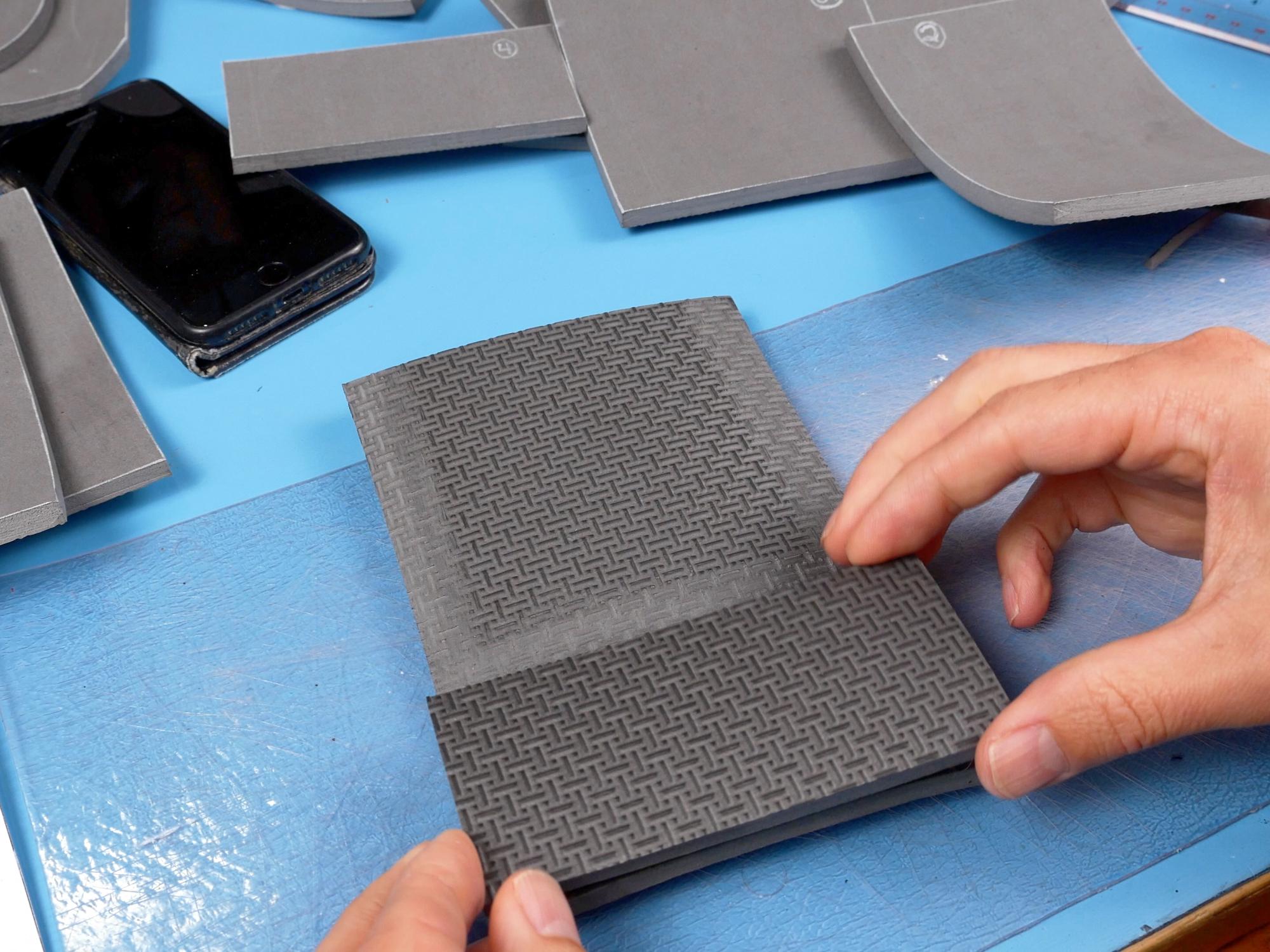
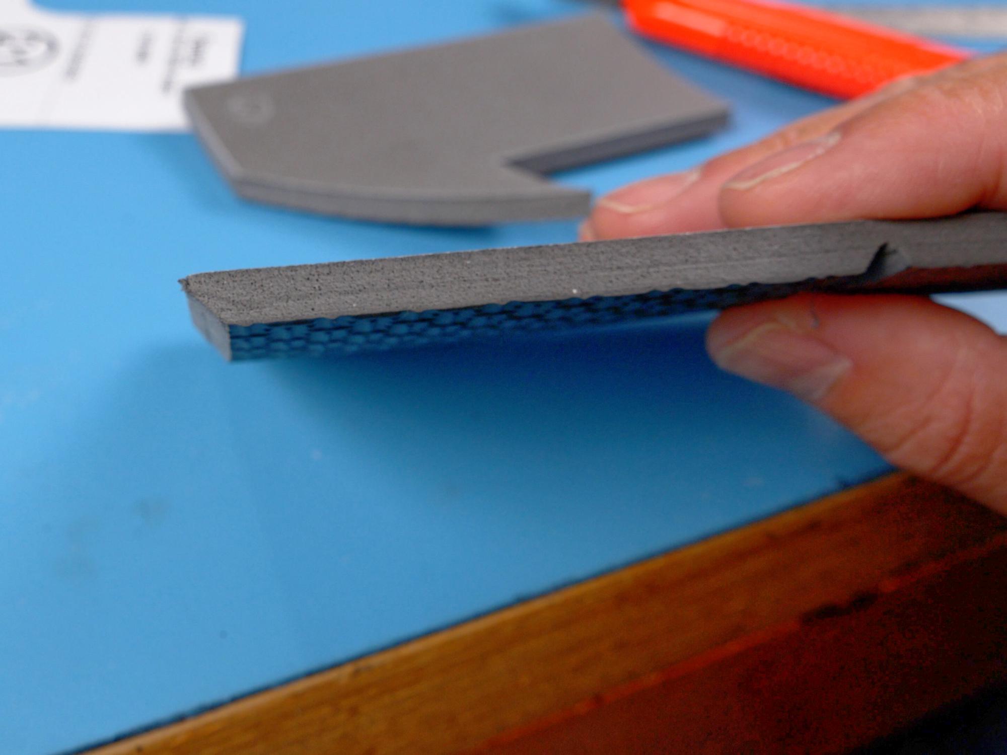
I use large 4 x 8 foot foam rolls that I get at my local Canadian Tire hardware store. It is sold as anti fatigue mat. The foam I use would be a medium density- if you use foam that is from something like a camping mat, it might be too soft, which makes it harder to cut cleanly and not as strong. The foam I use does also have a texture on one side, but you can keep it to the inside so it is hidden away!
Transfer the Pattern to Your Foam


Trace the back plate onto the 6 mm foam sheet.
Cut the speech bubble out of the back plate template.
Trace the speech bubble on 6 mm foam.
Cut the cyclotron pan pattern piece from inside the speech bubble, as well as the rest of the pattern pieces that are inside the back plate.
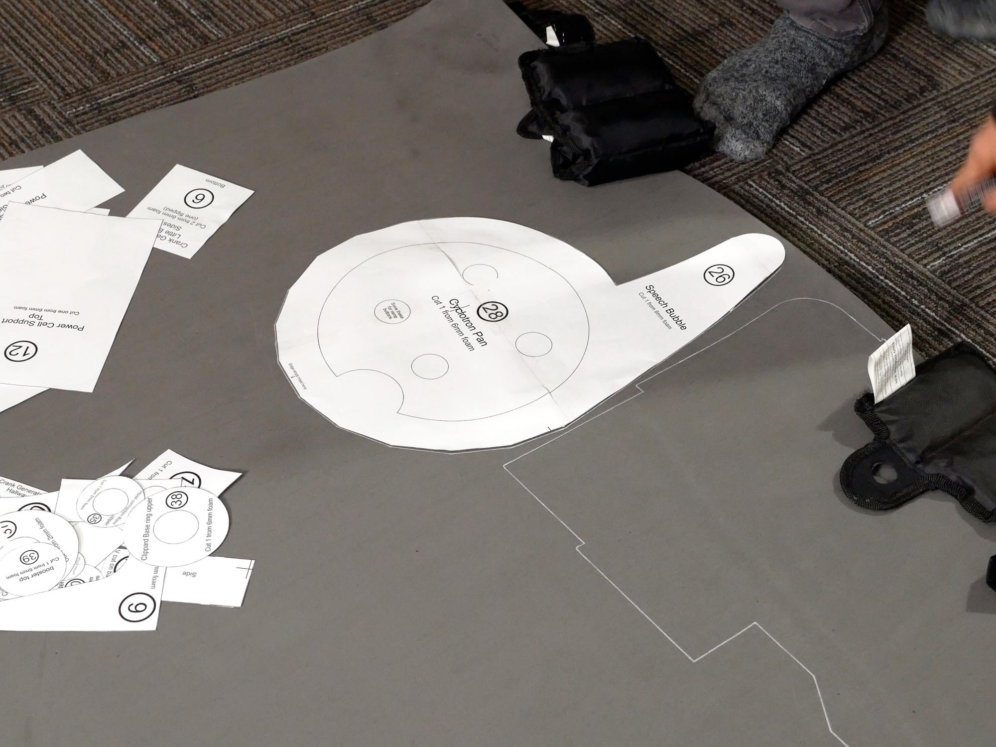
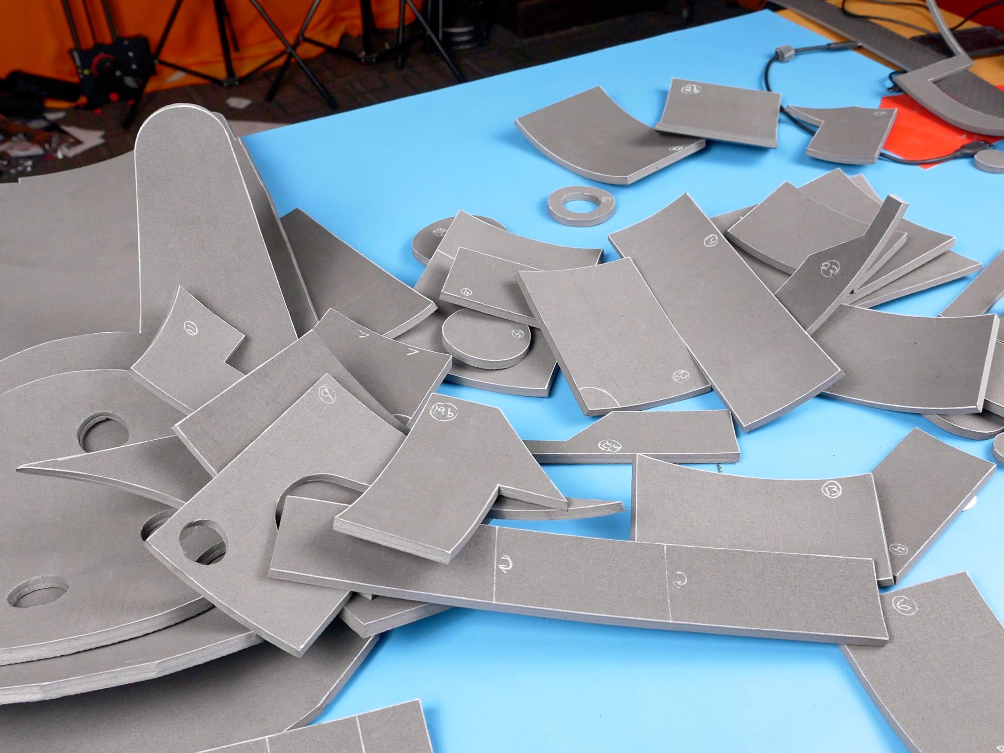
Once all the pattern pieces are cut out, you can lay them out on your foam mat to get an idea of how to make them fit as efficiently as possible. Each pattern piece has instructions on it as to what thickness of foam to cut it from, how many times it will need to be traced and whether you will need to flip the pattern piece over for the second tracing. Whenever you trace a flipped pattern piece, it is helpful if you label it with a “B” so that you know which are which.
Most of the pieces are cut from the 6 mm foam, however there are some that are cut from 2 mm thick craft foam. There are even some that are cut from both!
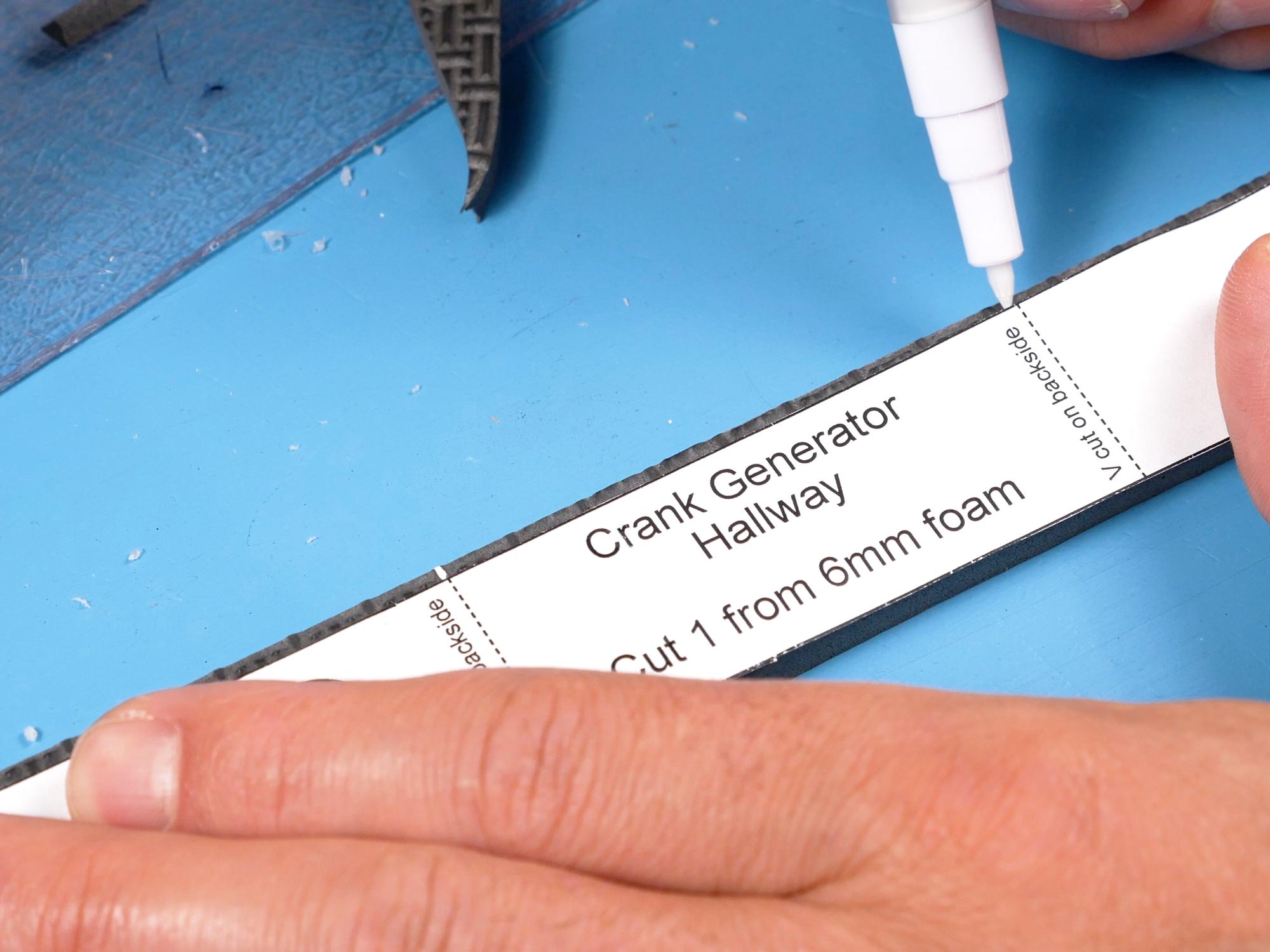
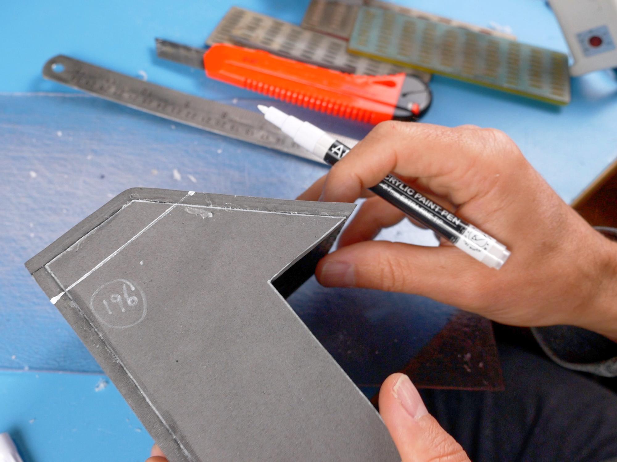
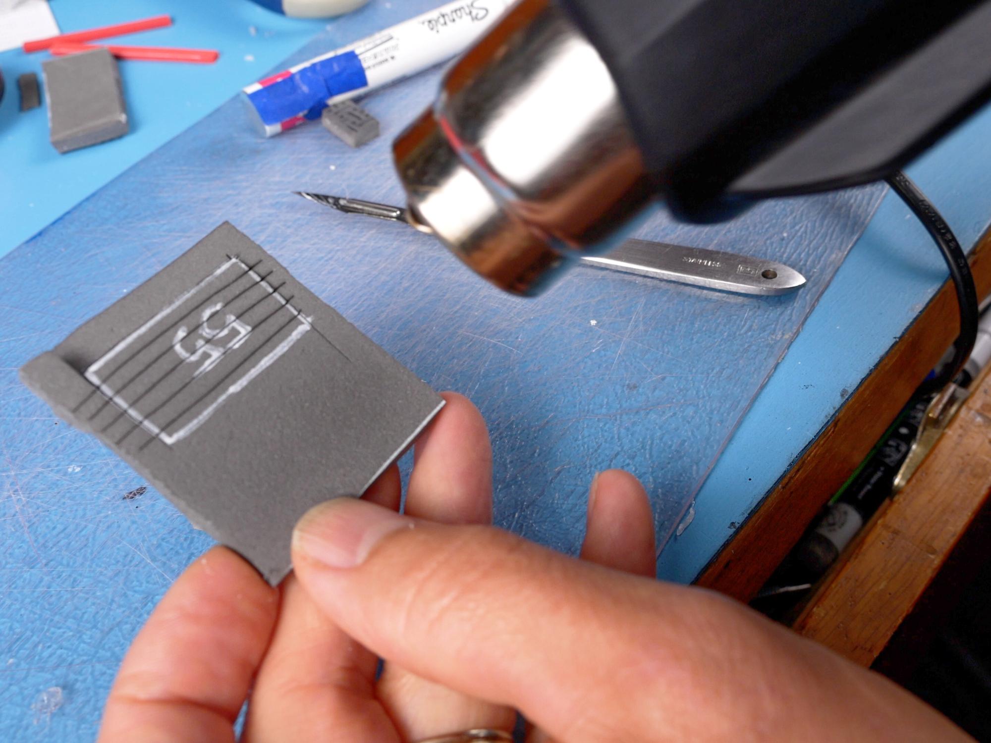
Carefully trace the pattern pieces onto the foam using either a light coloured gel pen or a paint pen. The reason for this is that standard sharpies or ball point pens seep through whatever paint goes over top of them.
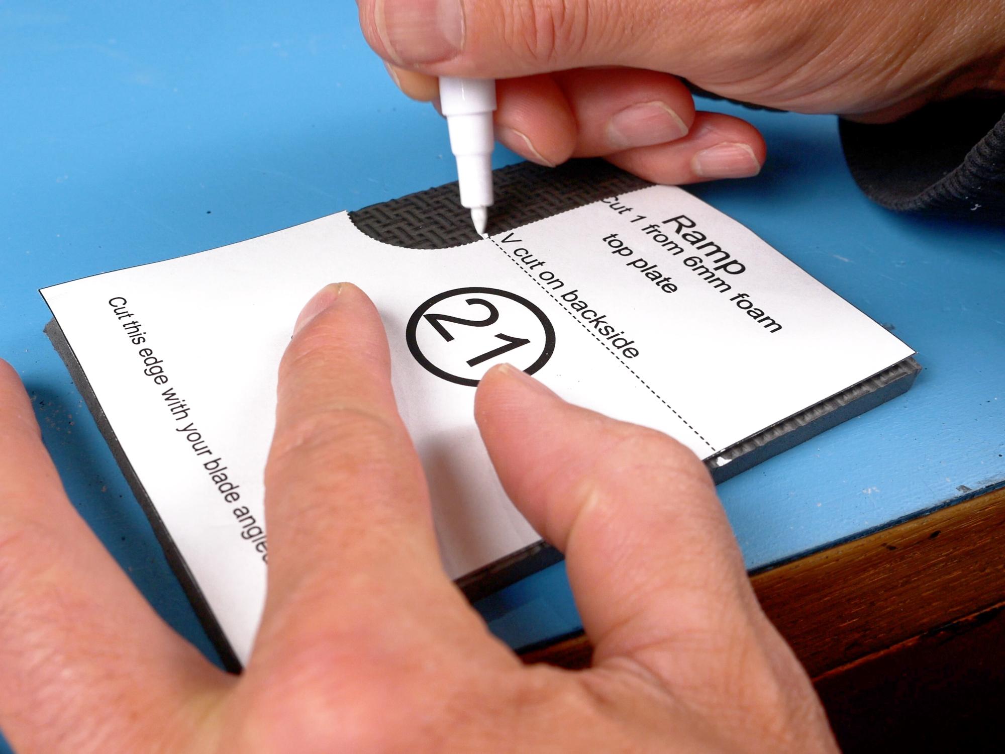
Some of the dotted lines are places where you will need to cut a “V” cut partway through the foam. Mark these lines to remind you of their placement. Most of the “V” cuts are on the back side of the foam, so I like to put a little “flip over” arrow beside those lines so I don’t forget and cut on the wrong side.
Piece 21 has one edge that needs to be cut at an inward angle, it is a good idea to mark that line as well because it is easy to forget when you are cutting all the pieces out.
Also, pieces 20 and 21 both have extra cut lines to mark. These will get cut after being assembled. First trace piece 20 and 21, then cut the pattern along the dotted lines, and then trace those lines onto the foam as well.
Quick Tip#1
Keep your eyes out for ankle weights at your local thrift stores, they make great weights for holding down uncooperative foam!
Quick Tip#2
If you want a stiffer, stronger (and heavier) pack, you can make the backplate out of a thin sheet of plywood or something similar
Cut the Foam

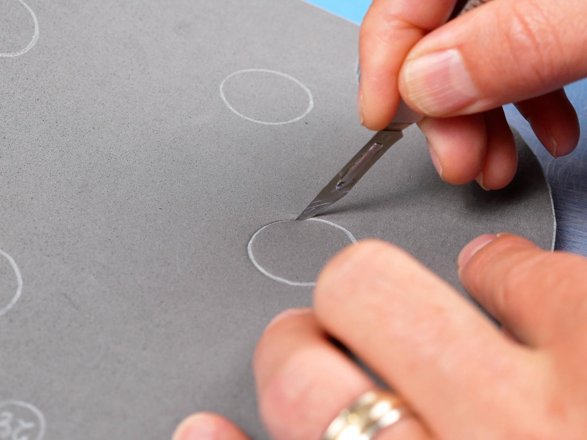
Using your sharp knife, cut directly on the lines. If the cuts look rough, that means your knife is too dull. Either get a new blade or sharpen your knife. It’ll make a ton of difference. Also, you will get a better quality cut by cutting along the same line a few times with moderate pressure rather than trying to cut all the way through in one pass. I use a utility knife for straight and large radius cuts, and I use a surgical scalpel with a #11 blade for tighter radius corners.
The only piece that needs to be cut at an angle is the bottom edge of piece 21. You can hold the angle of piece 19 against the edge of your blade to give you an idea of what angle you need to hold your knife.
The other cuts need to be as square as possible. I find that holding a square or the end of a ruler up against my knife blade every once in a while really helps my brain know what a nice vertical cut feels like.
**Remember to watch where your fingers are at all times and make sure you don’t cut them!
A Bit About Gluing


I use hot glue for my projects now, as I am a bit leery of breathing the fumes that go along with contact cement. It takes a little more practice, but you can still get very good results. The choice really is up to you. If you use quality contact cement, you will end up with a slightly more durable costume, particularly if it will be in hot places where hot glue could melt.
One thing that can really make life easier is to use a hot glue gun with adjustable temperature. That way you can turn the temperature down so it is just above the melting point of the glue. You don’t need to hold things as long, there are less fumes, and you don’t get burned as easily!
I like to glue a section about 5 cm long and hold it together until the glue cools. This time can vary depending on how hot your glue gun is, but for me it is about 30 seconds. The number one reason people have problems with hot glue is that they are just not holding the parts together long enough, so, if in doubt, hold the parts together a little longer.
If there is a long piece to glue, it is best to glue both ends so they line up properly first, then glue the rest of the seam in the centre. This reduces any errors due to the stretchable nature of the foam.
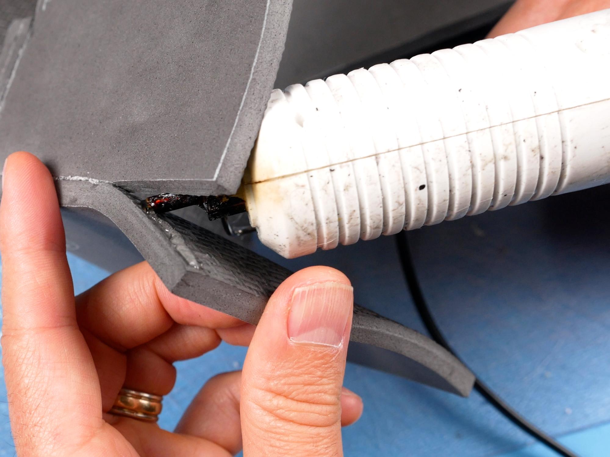
Hot glue sticks well to EVA foam, however foam that has a heat sealed texture is too smooth for the glue to grip, so if you are using foam with a texture on one side, every time you want to glue to that textured surface, you will need to sand the foam with a coarse sandpaper - around 50 or 80 grit.
** If you do use hot glue to make your proton pack, be careful not to leave it out in the sun on a hot day, or in a hot car because the glue will melt, leaving you with a hot mess! **
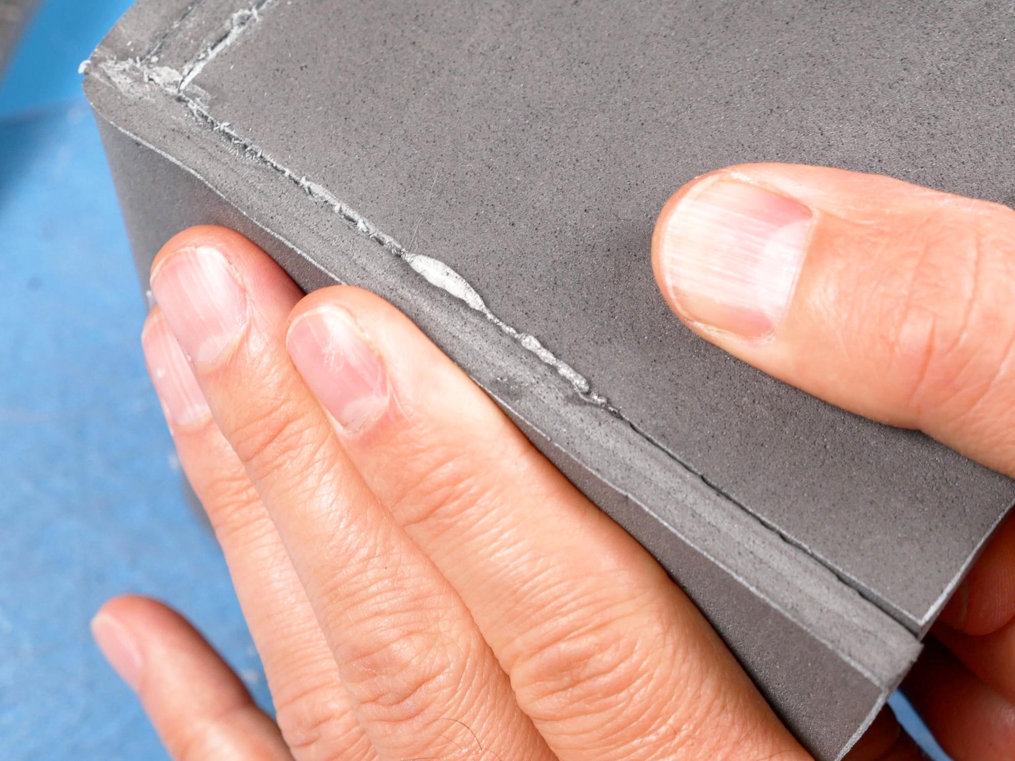
If you have problems getting clean seams with hot glue, one thing you can do is wait until the seam is cool and them rub along the seam with a piece of scrap foam. This softens the glue and allows you to rub away the excess.
Assemble the Crank Generator: Big Box


You’ll need: Pieces 2, 3, 4, 5
The crank generator is made of three sections: the big box, the little box, and the hallway. They will be made separately and then glued together.
The Big Box
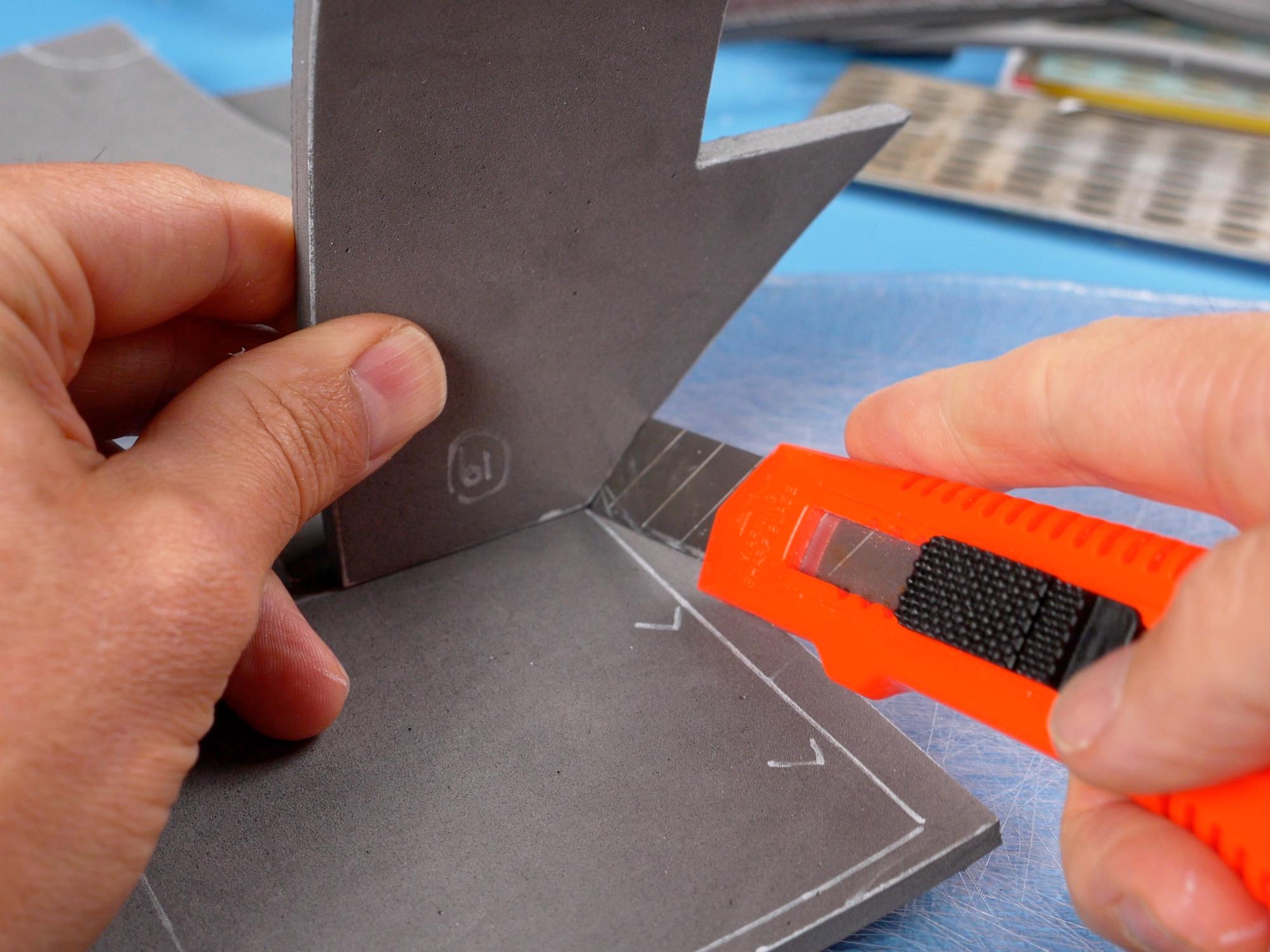
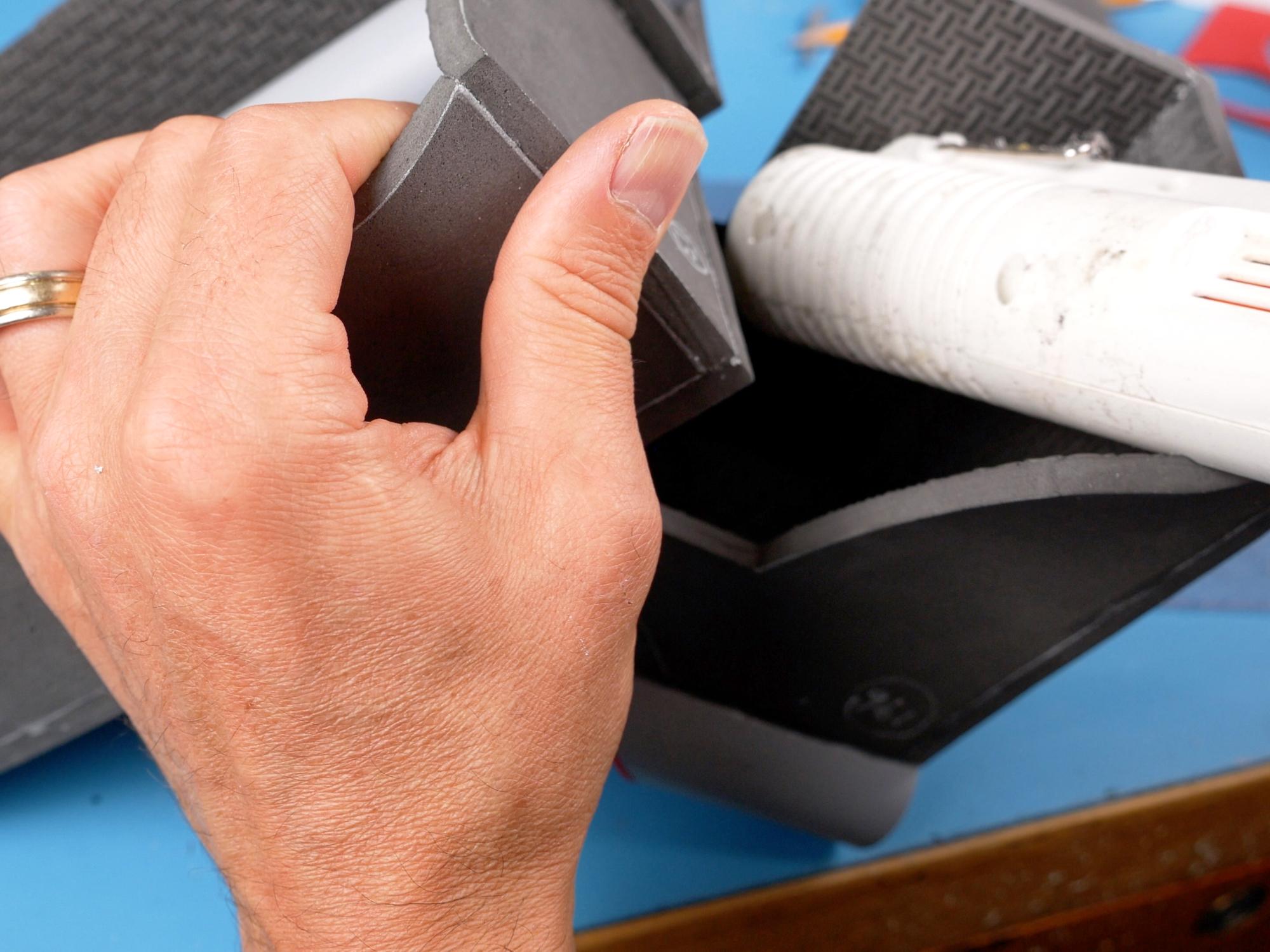
Mark the dotted V groove lines on the back of piece 5. Cut the “V” grooves on the back of piece 5.
You want the V groove to go a little more than halfway through the foam without actually cutting all the way through. Start with your knife a millimetre or two to one side of the line and angle the blade towards the line. Make a couple of light cuts like this and then go to the other side of the line and repeat the process, angling the other way. You basically want the deepest, pointiest part of the groove to end up directly under the line.
If you have not done this type of cut before, I would recommend trying a few on some scrap foam until you feel comfortable with it.
Sand the back of piece 5.
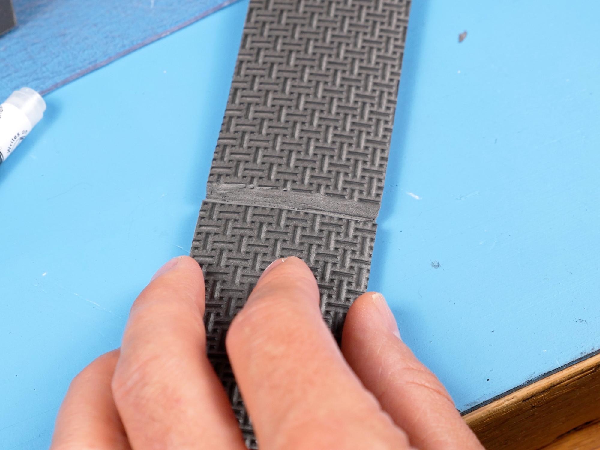
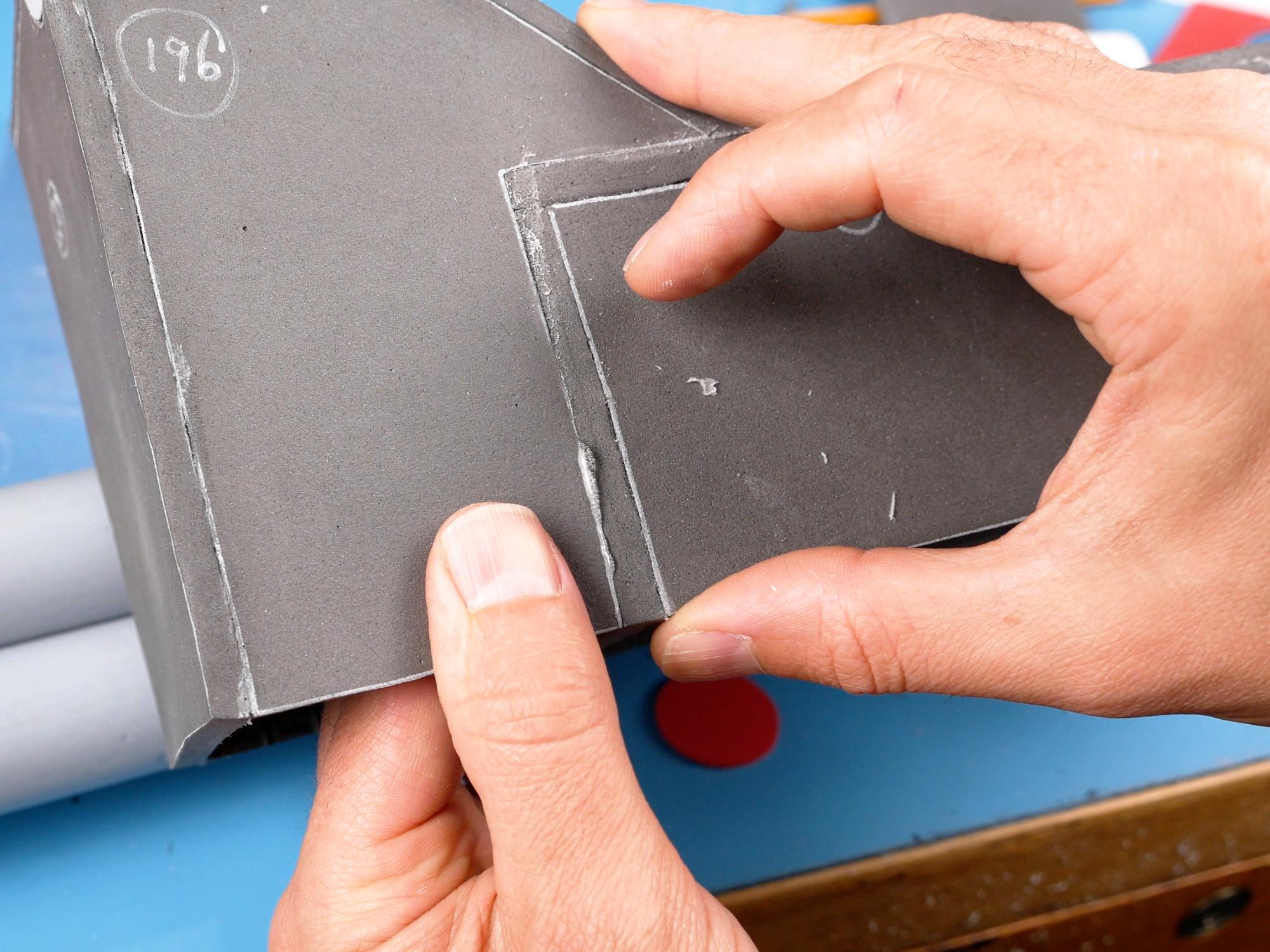
Glue piece 4 onto the back of piece 5, It should fit between the V groove and the end of the piece, lining up with the outside edge.
Apply glue in the V groove as well as beside it, where the edge of piece 4 will touch.
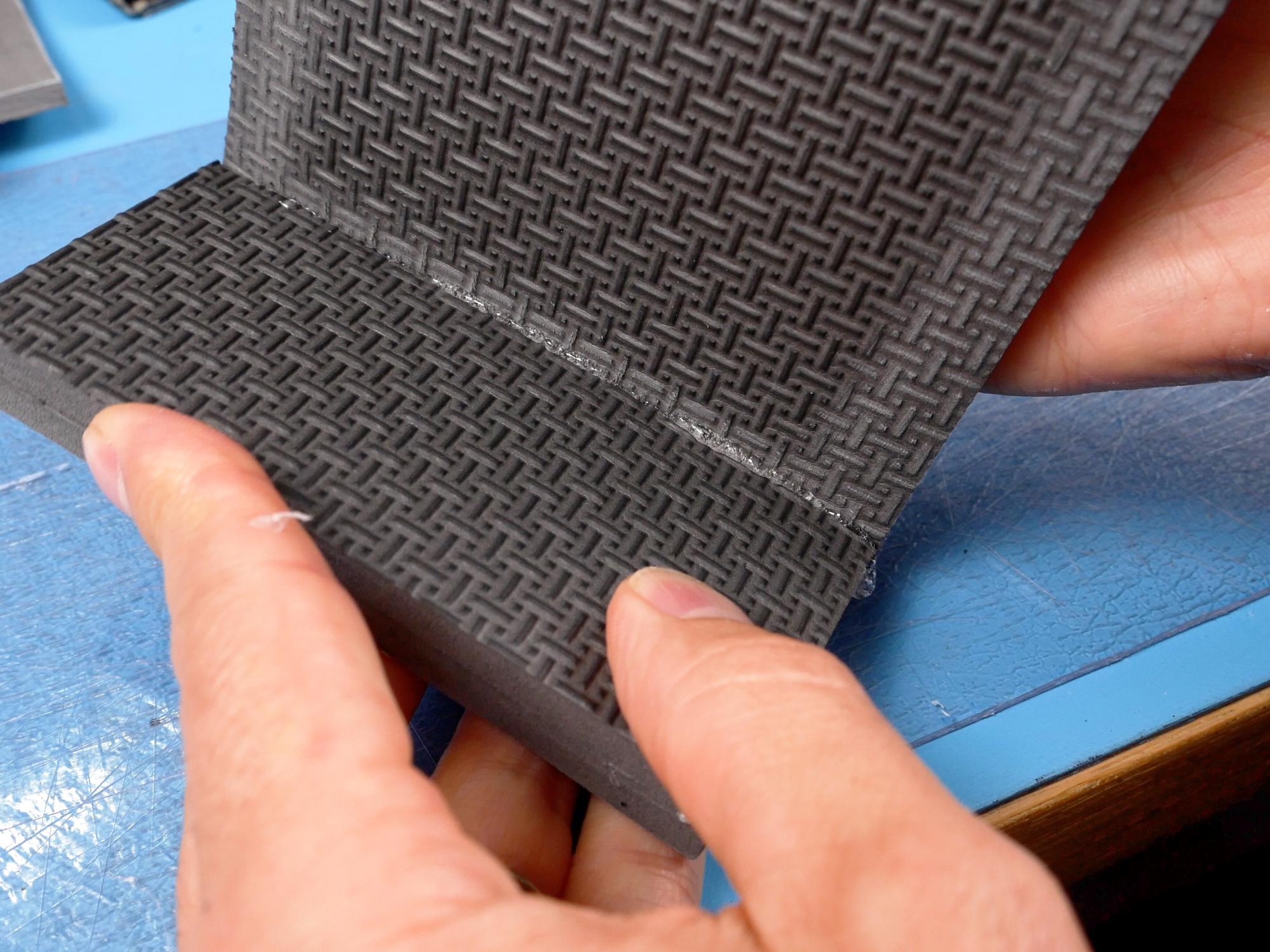
Bend the foam into a 90 degree angle, bending at the V groove. Hold it in position until the glue is cool.
Repeat the process for the second piece 5.
Sand the back of both piece 4s that you just glued.
Mark the top of both piece 2s. Piece 2 is a little tricky because one side of it slants in towards the top, so it is important that they get glued right side up!
Sand the back of piece both piece 2s along the top.
Glue piece (4+5) to piece 2, with the shorter segment resting on the top edge. Start by gluing the corner in place, and then work your way down the sides and across the top.
Glue the other piece (4+5) on the other side of piece 2. If there is a gap in the centre top of the box, that means you've done it right!
Glue the second piece 2 on the other side, completing the box with the hole on top.
Squeeze glue along the top edge of piece 2 on both sides, just on the inside where the gap in the top is. Also squeeze glue in from the back of the box, onto the back of the piece 4s.
Place piece 3 in from the back, closing the hole in the box. Flip the box right side up and make sure that piece 3 is nice and flush with the top edge of piece 2 where it is visible.
Clean up any messy glue seams by rubbing with some scrap foam.
Assemble the Crank Generator: Little Box


The Little Box
You’ll need: Pieces 6, 7
Mark and cut the V grooves on the back of piece 7.
Apply glue in the grooves and hold them at a right angles until the glue cools. This should give you a piece that looks like a flattened “U” .
Glue piece 6 into piece 7, starting at one corner and working your way around. Glue the other piece 6 into piece 7 on the other side, completing the box.
Depending on the exact placement of your V grooves, the bottom edges might not line up quite perfectly. This is not too hard to fix, as long as you do it before you have glued all the way down the sides. You can either stretch or compress the foam as you go, making up for sides that are too short or too long.
Assemble the Crank Generator: the Hallway
The Hallway
Mark and cut the V grooves on the back of piece 8.
Apply glue in the grooves and hold them at a right angles until the glue cools.
There are no sides to go on this piece as it connects the big box to the little box.
Assemble the Complete Crank Generator

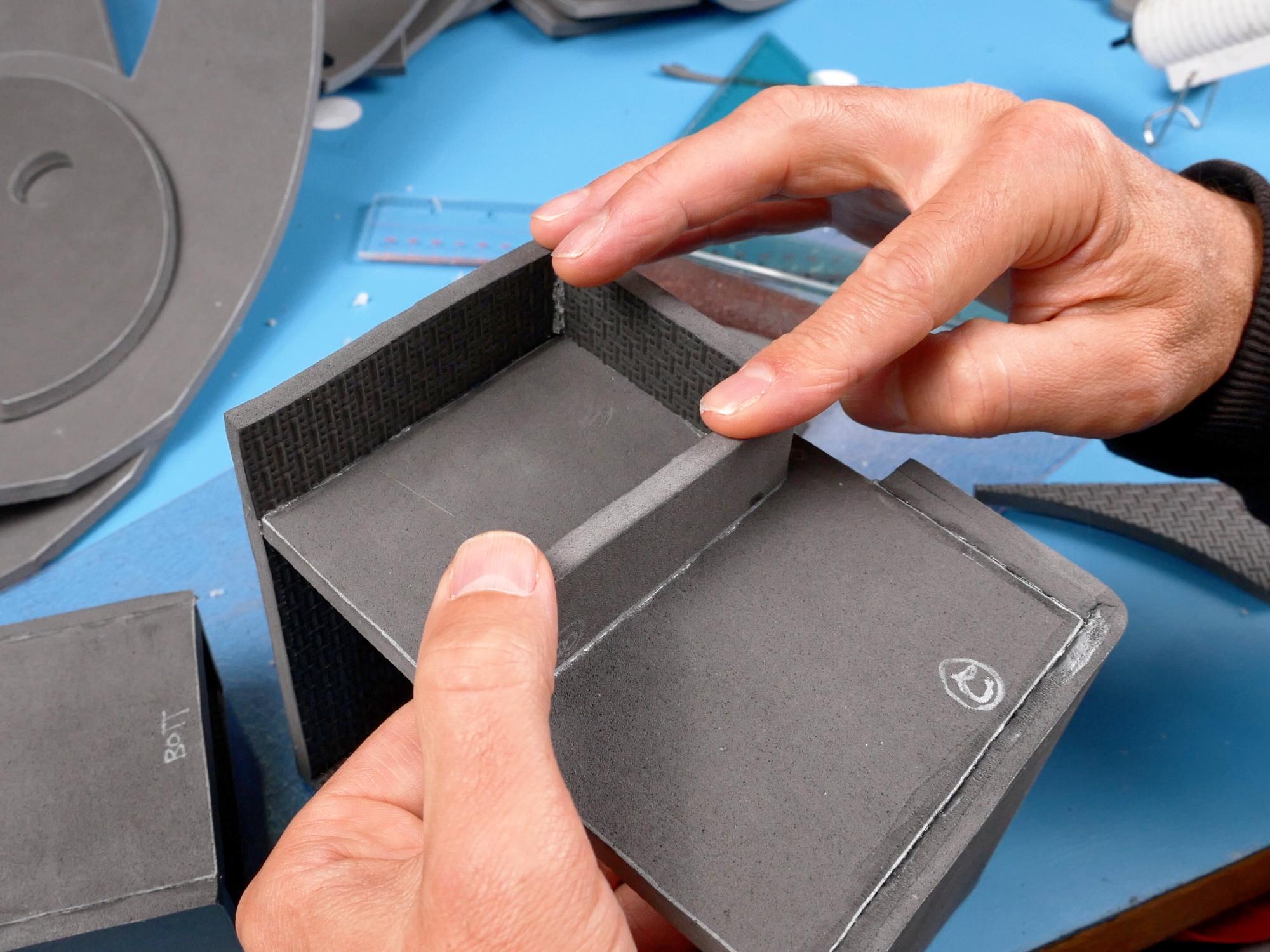


Putting it all together to make a crank generator
Hold the big box with piece 2 facing you, the large opening to the bottom, and with the angled edge on the right. I just want to make sure you don’t glue the other pieces to the wrong side of this box :)
With the big box positioned as mentioned, line up one edge of the hallway with the left edge of the big box. Glue that edge.
Use a square or something similar, to square up the other, unglued vertical edge of the hallway with the bottom of the big box. Mark where that edge is on the big box.
Glue the top and the edge you just marked, to the big box.
Glue the little box onto the hallway. This time line up the right side of the hallway with the right side of the little box. This works best if you apply the glue to the entire hallway edge and then put them together. It’s also a good idea to do this on a flat surface to keep everything lined up.
If you want to have rounded edges on the crank generator for better costume accuracy, you can use a rotary tool with an abrasive wheel to round them off.
Set the crank generator on the backplate to make sure that it fits properly. There is a notched out section on the top and the side which should line up with the corners of the crank generator.
Making Sharp Edges Less Sharp


Some of the parts on the original proton pack have rounded edges. It is possible to round off the edges of medium and high density EVA foam with a rotary tool and an abrasive bit. It is, however, a bit of trial and error finding the right abrasive bit that will work well for smoothing foam, I have a few different coarseness bits that I will try, and then choose the best one for that foam that day:)
Definitely wear a mask because there will be lots of foam dust flying everywhere!
The Part That Has No Name


You’ll need: Pieces 9, 10, 11
Glue the short, flat sections of piece 9 and 10 together.
Glue piece 11 overtop of the join between piece 9 and 10. It should match the pieces below it.
Power Cell Support Box


You’ll need: Pieces 12, 13, 14
• Sand the backs of pieces 12 and 13.
• Create the ends of the power cell support box by gluing one piece 13 to each end of piece 12. These are glued on top of piece 12 rather than beside.
• Glue the two piece 14s on the other two sides to complete the box.
The Power Cell


You’ll need: Pieces 15, 16, 17
Be aware that piece 15 is wider on one side of the cutout section than the other. It is important that the wider side is the side that will face the outside when it is positioned on the power cell support box. Also it is important that you mark the top of piece 17 as well.
• Glue the front of piece 15 to the top of piece 17.
• Glue piece 16 to piece 15 and 17. It should be glued to the wider side of piece 15. You just made
the power cell.
Glue Power Cell to Support Box


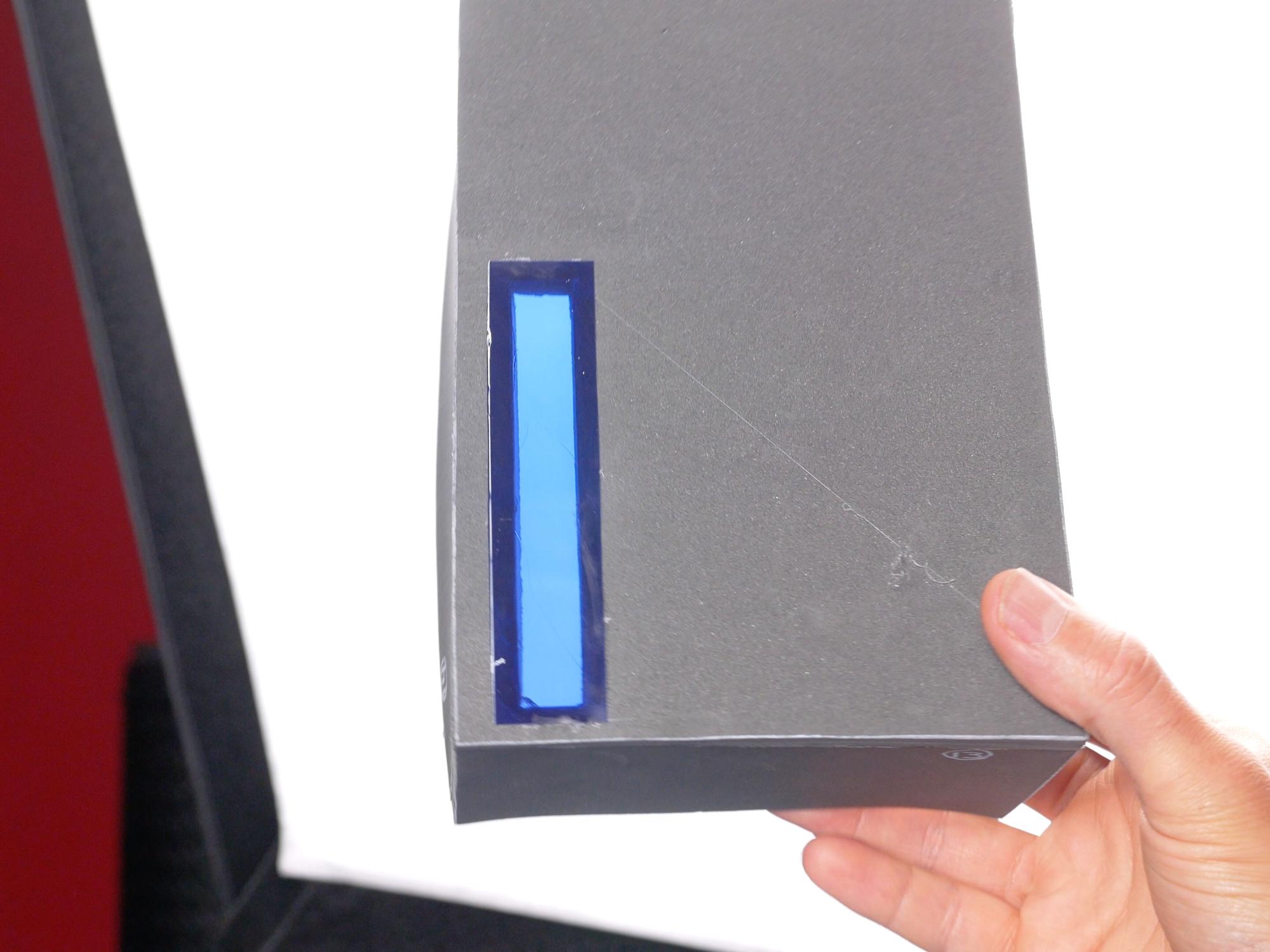


You’ll need: power cell, power cell support box, pattern piece 17
The power cell will sit on the bottom left corner of the support box. Set it in place and trace the rectangular cutout onto the support box.
Remove the power cell and draw a line slightly wider around the line you just traced.
Cut a rectangle in the support box, following the wider line.
Cut a strip of blue translucent plastic, slightly wider and longer than the hole you just cut. Glue the strip over the hole in the power cell support box. I used a plastic folder I had lying around.
Glue the power cell into place on the corner of the support box. It is a good idea to turn up your glue gun a bit for this, because you need to apply glue to all three sides of the power cell, and get it positioned before any of the glue starts to cool.
Using the circular holes on the front of the power cell as a template, cut them all the way through into the power cell support box.
Place the paper pattern piece 17 on the back of the box in line with the holes at the front. Trace only the hole closest to the top, and cut it out.
Pipes and Holes


You’ll need: 1" PVC conduit, power cell
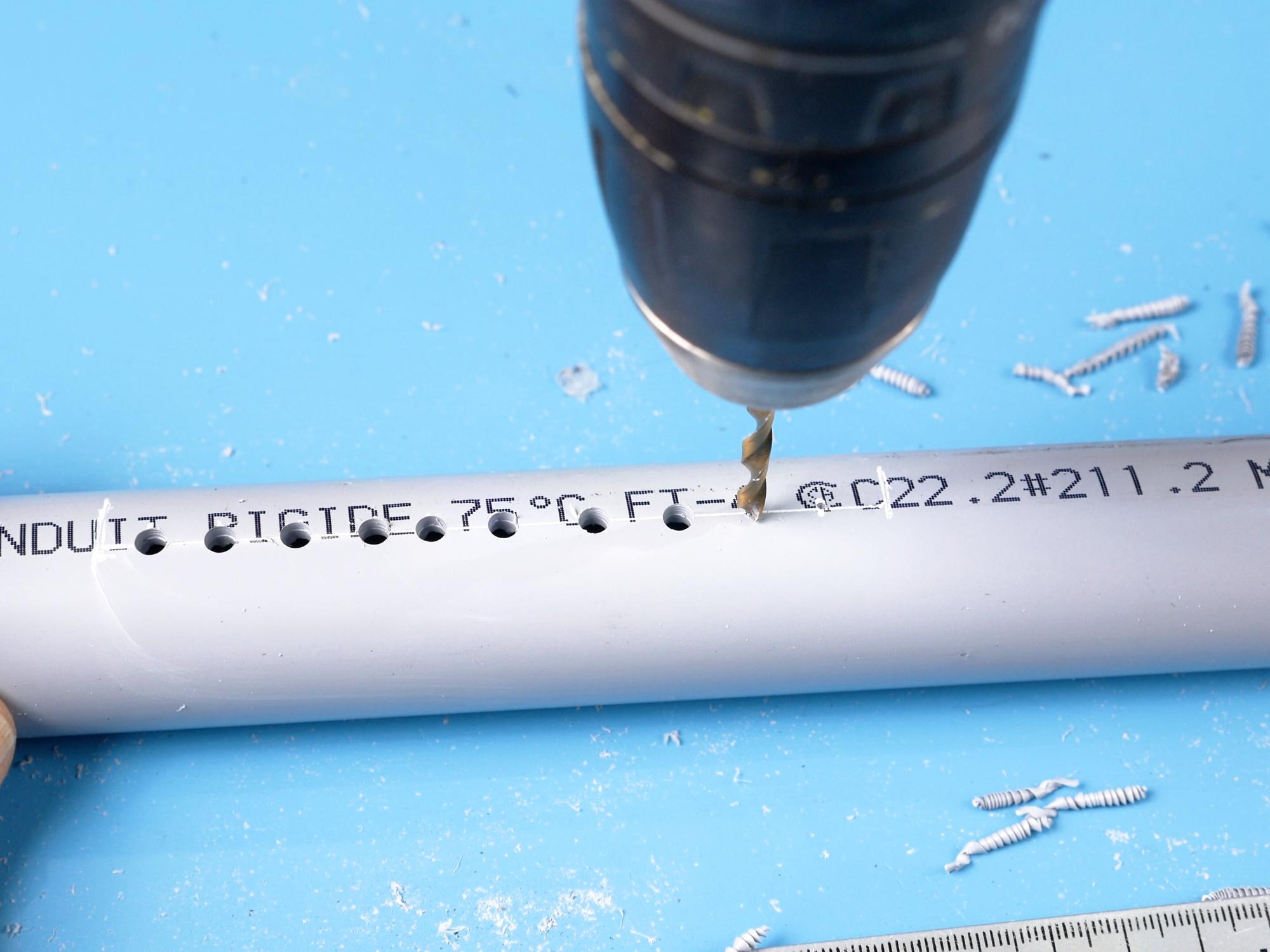
Cut a 39 cm (15.35”) long piece of 1” PVC conduit.
Make a mark at 11.5 cm and one at 22 cm from one end of the conduit. Draw a straight line between those marks.
Along the straight line, make a mark every centimetre.
Using a 4 mm drill bit, drill a hole at every mark.
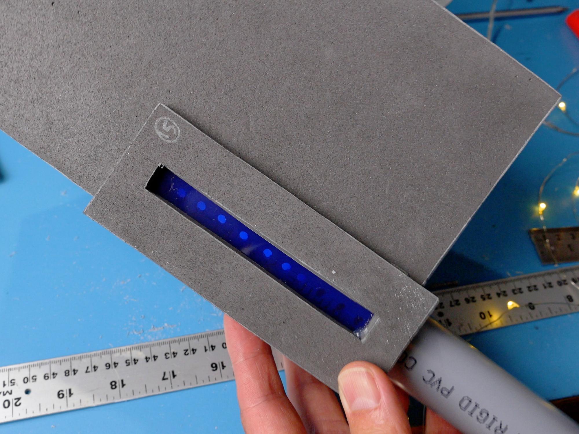
Slide the conduit into the power cell, all the way until it goes into the hole at the back of the support box. Turn it until the line of holes is facing the translucent blue plastic window. The idea is that you can drop a glow stick down the tube, and the holes will allow the light to come through, making it look like there are individual lights.
*there are many other, more realistic ways to make the lighting on the pack, I just tried to keep things simple and analogue. If you're good with LEDs, go for it!
Cut a 20 cm piece of 1” PVC conduit.
Push it in through the bottom hole in the power cell until the front edge lines up with the front edge of the first pipe.
Drill a hole through both pipes from the back, just outside of the power cell. Screw a screw into that hole that is long enough to go almost all the way through both pipes. It needs to be this long because this screw will also serve to stop the glow stick from falling all the way through the pipe.
Drill another hole through both pipes near the other end as well.
Remove both pipes from the box.
Use an abrasive pad to slightly roughen the PVC pipe in order to help for paint adhesion later.
Countersink the screw holes on the back of the PVC pipes.
Put the pipes back into the power cell and screw them together.
Apply glue to the hole at the back of the power cell support box and then push the pipe into the hole.
Glue the front edge of the pipe from the inside of the box.
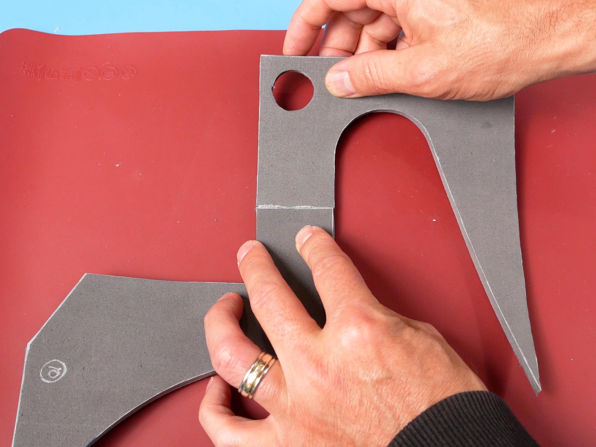
The Ramp


You’ll need: Pieces 19, 20, 21,
Mark and cut the V groove on the back of piece 21. This cut doesn’t need to be quite as wide because the foam is not being bent all the way to 90 degrees.
Verify that the bottom edge of piece 21 is cut at an angle like it is supposed to be.
Piece 20 gets glued to the top edge of piece 21.
Glue piece 19 and 19b so that the long edge matches up to the long edge of piece 20. This makes the ramp.
Glue the short edge along the top of the ramp.
Apply glue to the V cut and hold it at the correct angle while it cools. Glue the rest of piece 21 to the angled edges of piece 19.
Use a ruler to extend the cut out lines across the side of piece 19.
Make a Tube for the Ramp


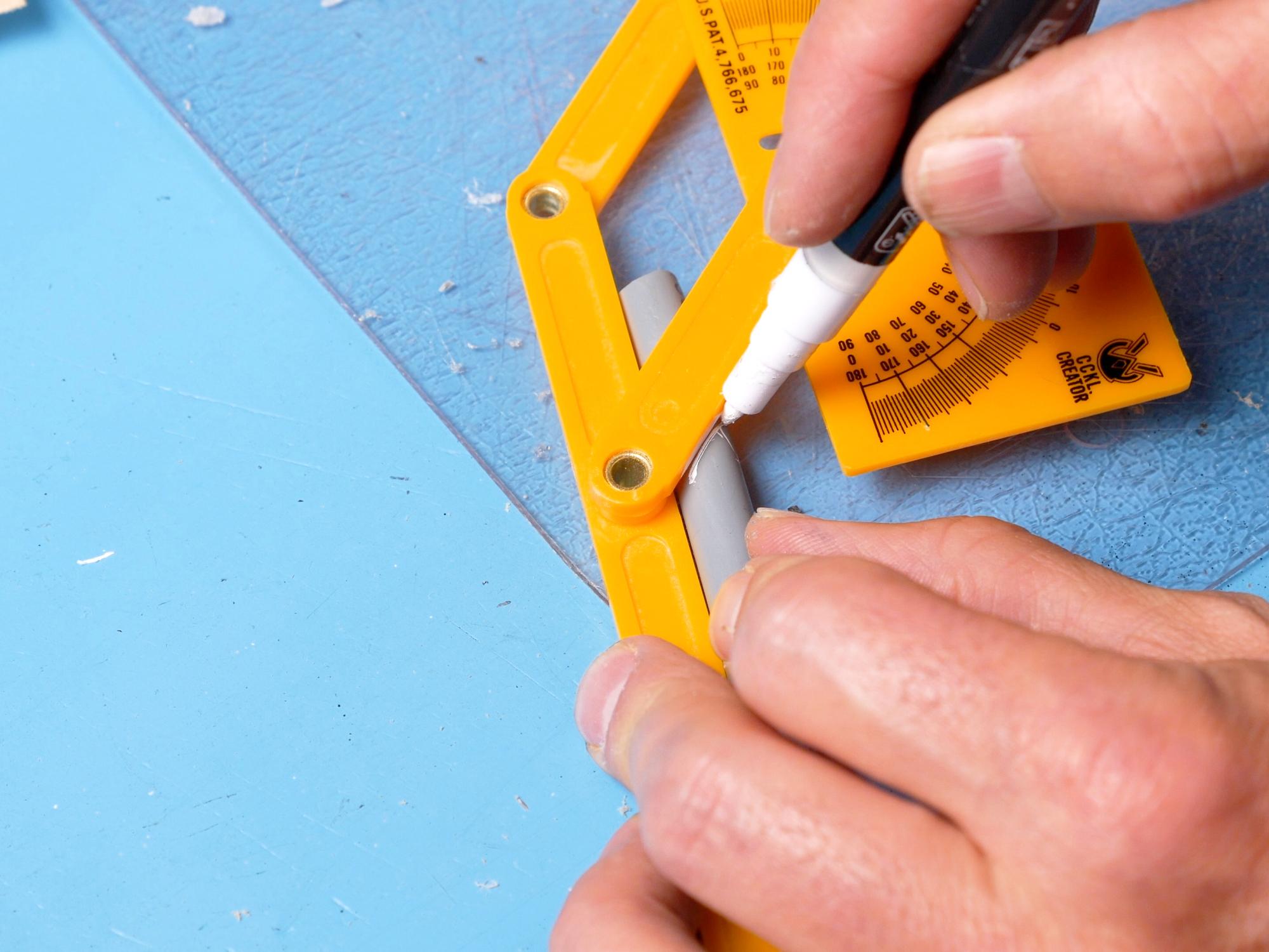
Cut a 77 mm long piece of PVC with one end cut at a 45 degree angle. I include a paper template to help make a 45 degree line on the PVC pipe. Just wrap it around the pipe and line up the edges before tracing.
Sand both ends of the PVC pipe smooth, and rub it with an abrasive pad. Glue the angled end of the PVC pipe down onto a sheet of 2 mm foam.
Cut around the pipe end, trying to keep the blade following the angle of the pipe. It’s not that easy to do, and I had to clean up the edges of the 2 mm foam a bit afterwards with a rotary tool.
Add the Ramp Tube


You’ll need: Piece 44, PVC Conduit, Ramp
Cut along the cut lines at the top corner of the ramp. This is to allow the angled PVC pipe to sit in that cut out. Make sure when cutting on the angled section of the ramp that you keep your knife parallel to the bottom edge of the ramp. You may also need to angle the cut on the outside edge afterwards.
Glue the PVC into the cutout. The flat edge should be flush with the back of the ramp, and the front edge should extend a little ways past the front of the ramp.
Glue piece 44 into the back hole of the PVC pipe.
Attach Ramp to Power Cell


Glue the ramp beside the the power cell. It should be flush with the edge of the support box, with maybe a little gap between it and the power cell. Glue the front edge down first, and make sure it is totally cooled before you try to glue more. Glue the inside edges down as best you can - this involves pivoting the ramp up to allow glue gun access to that edge. Once the inside edge is glued, gluing the outside edge is easy.
Glue a piece 44 in the bottom end of each of the pipes coming out of the power cell.
Glue a piece 18 over top of the piece 44 in the end of each pipe. The extra foam thickness is to add some strength because wires will be getting glued into the pipe ends eventually.
Use your glue gun to create a weld-bead effect around the ends of the pipes.
The Grain Elevator


You’ll need: Pieces 22, 23, 24, 25
Mark and cut the V groove on the back of piece 24.
Cut the V groove on the front of piece 24.
Glue the straight sides of piece 22 and 22b onto piece 23.
Apply glue on the front V groove on piece 24 and hold it in position against the rest of the grain elevator until it cools.
Apply glue on the back V groove on piece 24 and hold it in position until it cools. Glue piece 24 to the rest of the grain elevator.
Glue piece 25 on top.
Speech Bubble: the Strip


You’ll Need: Pattern piece 27, strips of 6 mm foam, speech bubble (piece 26)
Cut two long strips of 6 mm foam the width of pattern piece 27. I cut them each 4 feet long.
Line up the end of piece 27 with the end of one of the strips and mark the cut lines on the front. From the last cut line measure another 48 cm (18.9”) and cut the strip to that length.
Repeat this to make a second strip, but this time you only need to add 28 cm (11”) past the last cut line.
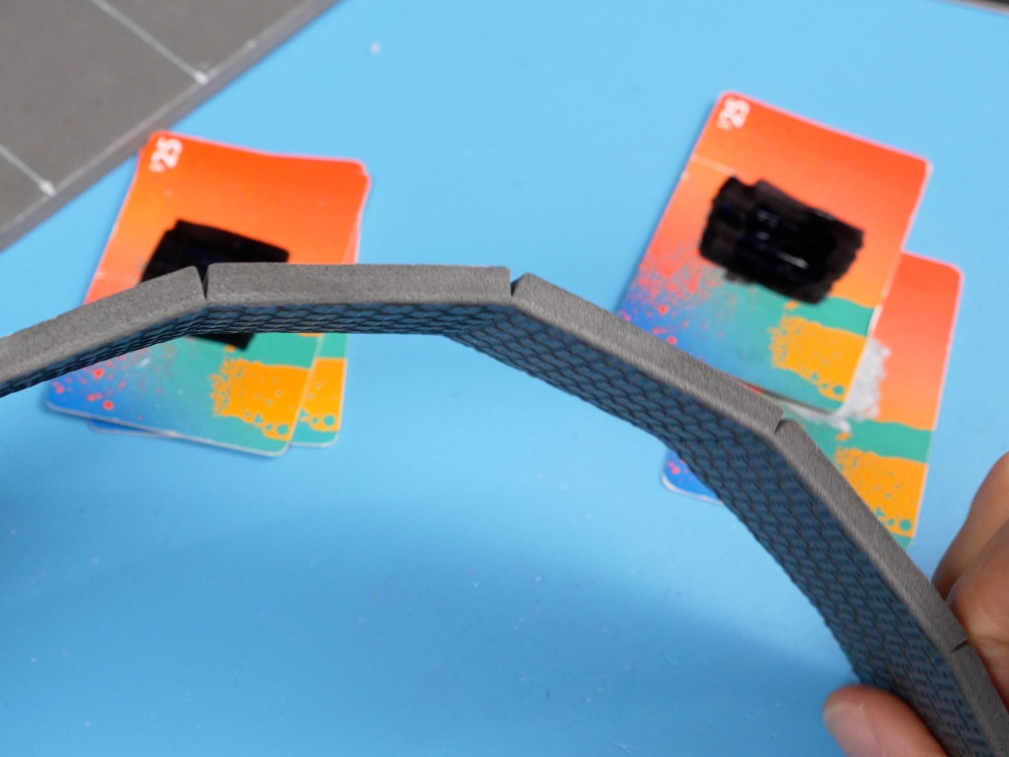
Get a few old gift cards and make a stack on either side of the strip. I used a stack of two cards on each side and that seemed quite good. Remove the blade from your utility knife and hold it straight across the foam so that when it cuts down, both ends will be stopped by the gift cards at the same time. Use a sawing motion to cut straight down on the lines until you hit the gift cards. Repeat for all the cut lines on both strips. If all went well, you will have cuts that go almost, but not all the way through the foam strip.
Assemble the Speech Bubble


You’ll Need: speech bubble strips, speech bubble (piece 26),
On the pattern for the speech bubble, there is an “edge strips meet here” arrow. Mark that on your foam speech bubble.
Glue the longer strip to the outside edge of the speech bubble, starting in the centre of the segment you just marked and lining up each cut in the strip with each corner going around the bottom edge. The longer strip will start at the bottom and go counter clockwise up and around the narrow section of the speech bubble until it gets to the right angle corner.
Trim the longer strip right in line with the corner where it ends. It’s a good idea to use a square to mark this cut so that you end up with a nice perpendicular edge at the end.
Back at the bottom of the speech bubble, glue the shorter edge strip to the end of the longer edge strip and continue gluing the strip clockwise around the speech bubble, lining it all up the same way you did with the longer strip.
When the shorter strip gets all the way to the corner, glue the side of it to the end of the long strip. Again, make sure that you are gluing it perpendicular to the speech bubble.
Cut a 63 cm (24.8”) long strip of foam from the leftovers of the side strips. Glue it in a loop and glue that loop in the centre of the speech bubble. This is just to give some extra support from the inside so that the foam doesn’t cave in.
The Cyclotron Pan


You’ll need: 6 mm foam, pattern piece 29, Cylotron Pan (piece 28), Speech Bubble, LED bulbs, velcro
Cut a strip of 6 mm foam the width of piece 29, and 63 cm (24.8”) long.
Glue the strip to the edge of the cyclotron pan, lining up the beginning of the strip with the edge of the half circle cut out. Glue about 3/4 of the way around, and then glue the other end of the strip to the other edge of the cut-out. This makes it easier to make sure that the edge strip will end in the right place, and then you can stretch or compress the foam as you glue the remaining area.
If you want a rounded edge, you can do that with a rotary tool.
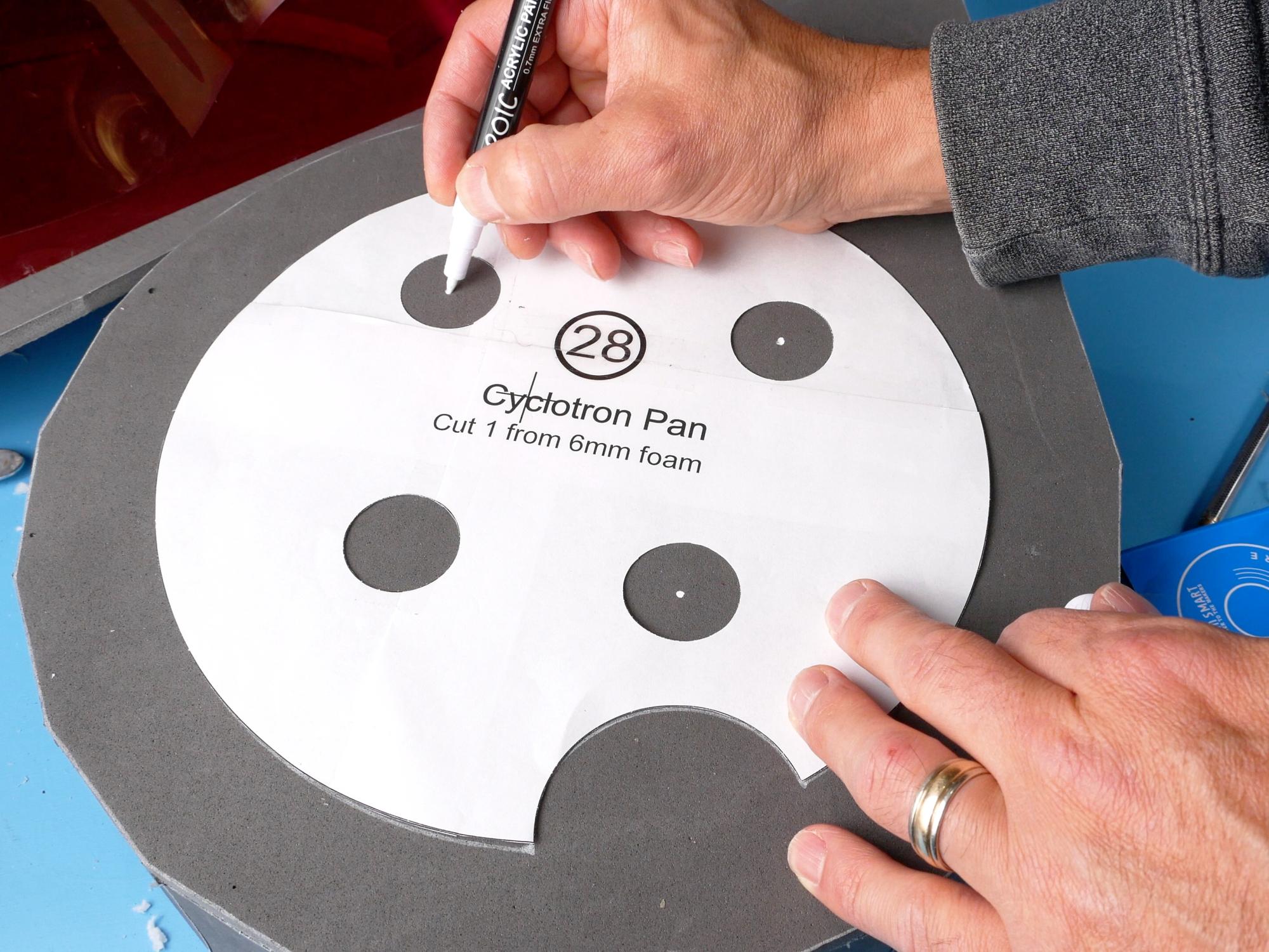
Put the speech bubble template that has the cyclotron pan cut out of it onto the foam speech bubble. Trace the location of the cyclotron pan.
Place the cyclotron pan template in its position on the speech bubble. Mark the centre of each of the four holes.
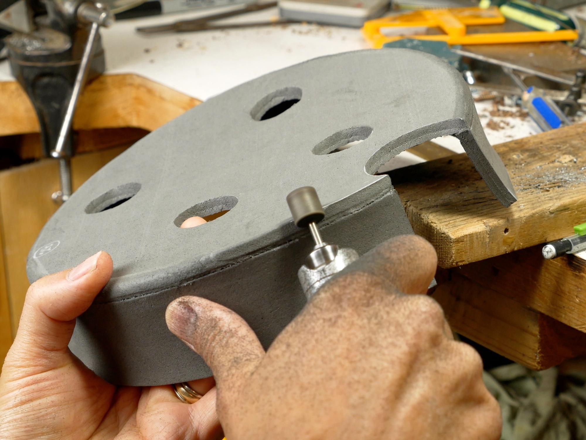
Use a 4 mm punch to punch holes where you made the marks. It’s a lot easier to punch the holes with a firm surface to punch into. I used a peanut butter jar so that it was raised off the table and wouldn’t damage the sides of the speech bubble.
Get some LED bulbs. (I got mine from an old flashlight)
Wire up the LEDs and push one through each 4 mm hole. (I’ll leave the electronics lesson to someone else, I know just enough to be dangerous:))
Glue the LEDs from behind and glue the wires down as well.
I found my LEDs were much too blue, so I used a translucent red folder and cut some discs from it that I glued over top of the LEDs.
Cut a hole in the centre of the back plate. This is where you can store the battery pack for the LEDs. I just put a bit of velcro on the battery pack and some velcro in the hole.
Put It Together


You’ll need: All the assembled parts
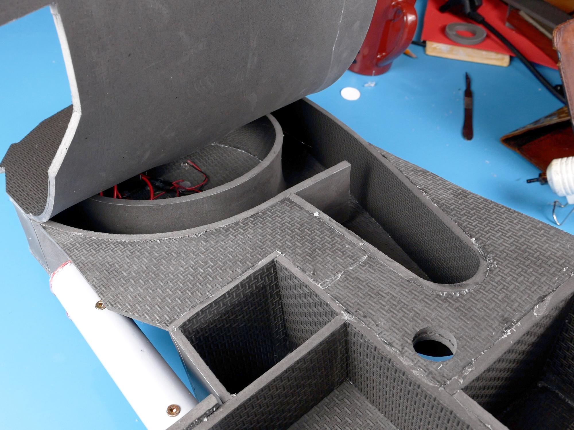
It’s time to take all the separate components and put them all together! Before you start gluing, it’s a really good idea to lay out all the pieces on the back plate and make sure they are all going to actually fit together properly. If not, it’s better to know now than later.
Assembling the parts is much easier if done from the back, so flip everything over and get ready!
Start by gluing the piece that has no name to the speech bubble. Try to keep all the edges flush on the back so that it will be easier when you need to glue on the back plate.
Glue the power cell support box to the piece that has no name. Start at the inside corner and work your way out from there.
Glue the crank generator to the side of the power cell, then glue the bottom edge of the crank generator to the edge of the piece that has no name.
Glue on the Back Plate


Now that all the pieces are together, you need to glue on the back plate. Set it on the back plate and make sure everything is still going to fit.
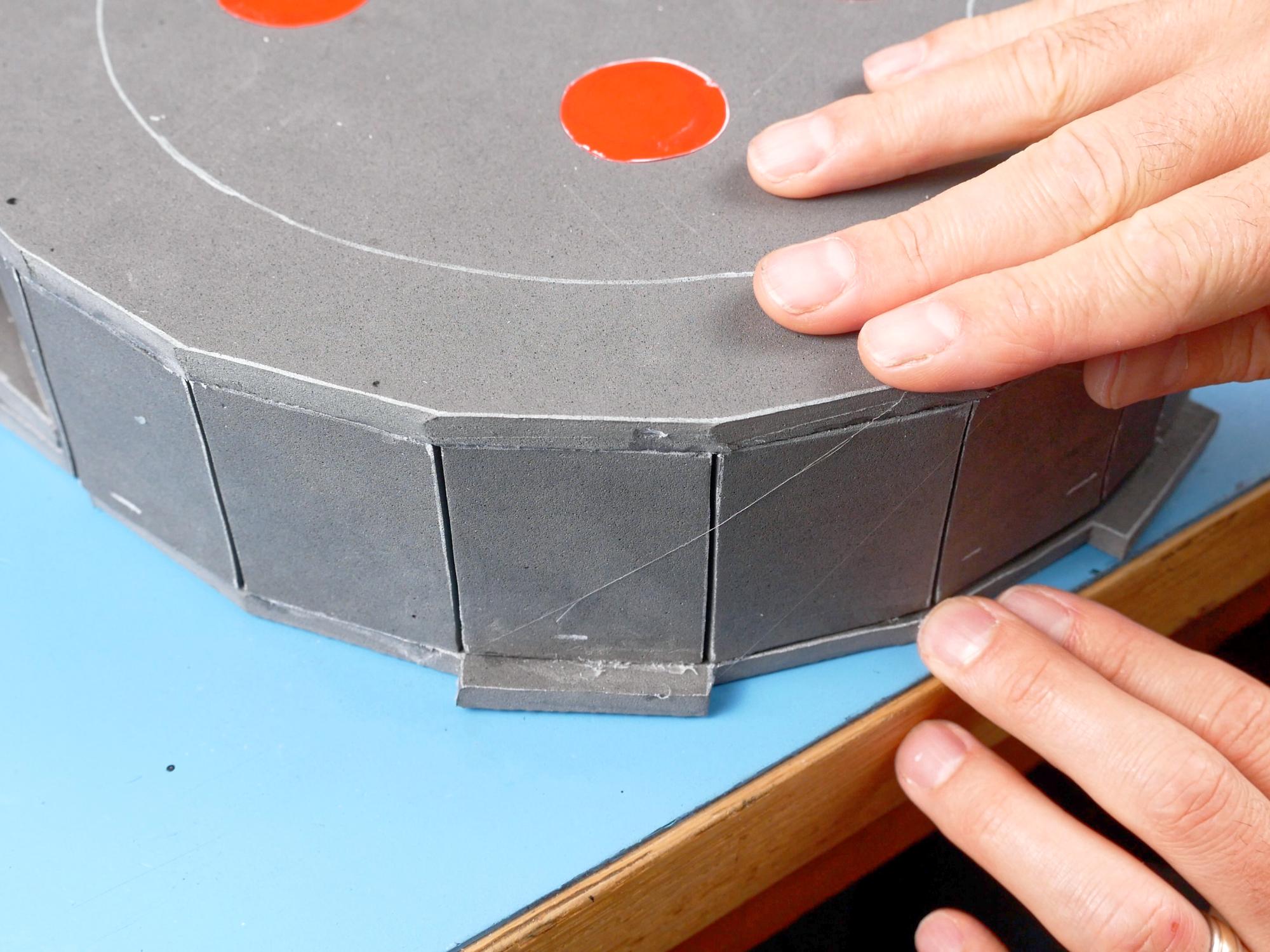
Start gluing at the bottom of the speech bubble, on the flat facets. Line them up with the flat edges on the back plate.
Once you run out of flat facets, flip the pack upside down. Lift the back plate away from the pack so that you can get your glue gun in there. Glue a section at a time, gluing from the back, then turning the pack over and pressing down from the front on a flat surface until the glue cools. This is so that the pack has the best chance of staying nice and flat.
The only place the pack doesn’t sit on top of the backplate is the little piece in front of the power cell. It extends lower than the rest of the pack and butts up to the side of the back plate.
*Before you glue the backplate on, make sure you know how/if you are going to attach straps to the pack. There needs to be reinforcement inside the pack anywhere you are attaching straps etc. Glue in some wood blocks or similar in the places you need reinforcement before closing up the back. You can watch my other videos which show how I made the pack frame and added reinforcements to the pack. You can find those videos at the end of this instructable.
More Pipe


You’ll need: 2" ABS pipe
Cut 3 pieces of 2 inch ABS pipe. One 6 cm (2.3”) long, one 9 cm (3.5”) long and one 24 cm (9.4”) long, with a 45 degree angle cut on one end.
Use an abrasive pad to prep the pipes for painting.
Add a Filter


You’ll need: Pieces 30, 31, 32, 9 cm long ABS pipe, Cyclotron Pan
Glue piece 30 on top of the 9 cm pipe.
Wrap piece 31 around the bottom of the pipe. To get a nice smooth foam wrap, don’t use too much glue, and try to spread it out as thinly as possible so that it doesn’t create bumps in the surface.
When it is glued halfway around, check to make sure the ends will meet up. If not you might be able to stretch or trim the piece a little to make it work.
Glue strip 32 around the top, covering the edge of the foam cap.
The pattern strip for piece 32 also has markings on it for the holes that need to be be drilled. Wrap it around the area of pipe that is not covered by foam, and centre it in the middle.
Use a sharp pointy object to mark the centre of all the drill holes through the paper.
Drill a small pilot hole through all the marks you made.
Drill out the pilot holes with a 10 mm (3/8”) drill bit.
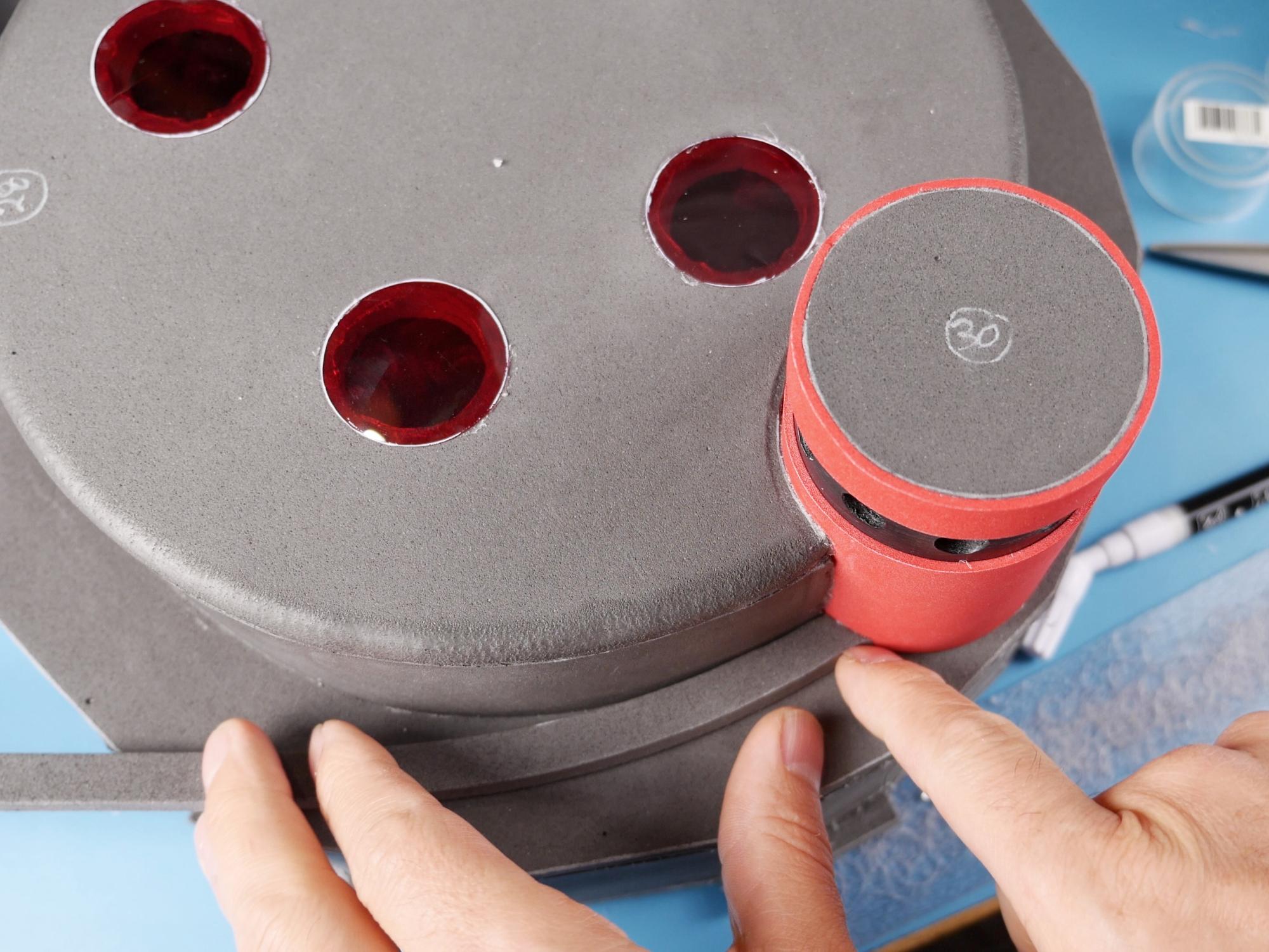
Glue the finished filter in the circular cut-out in the cyclotron pan. Make sure when you glue the sides of the pan to the filter that they are being glued square to the bottom.
Glue the cyclotron pan down to the speech bubble. Start by applying glue to the entire bottom rim of the filter and setting it in place. Then glue around the pan, lifting the edge of the pan slightly to allow space to get the glue gun in there.
The Hydrogen Gas Actuator (HGA)


You’ll need: Pieces 18, 30, 6cm ABS pipe
Glue piece 18 on top of piece 30.
Glue that little stack on the top of the 6 cm ABS pipe. You have just made the Hydrogen Gas Actuator, or HGA
Glue the HGA onto the side of the crank generator, just above the little box. I located mine in about the middle of the crank generator, but when I was wiring it all up, I figured it probably should go just a little higher.
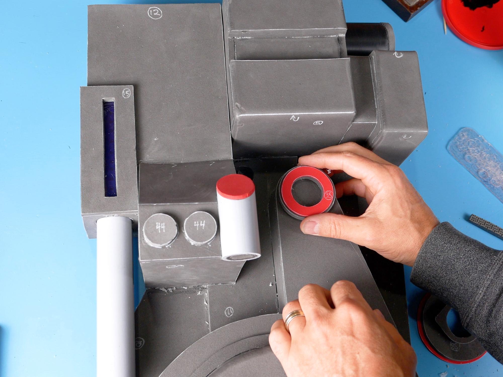
Add the Light Washers


You’ll need: Pieces 33, pattern piece 42, translucent red plastic
Use pattern piece 42 to trace 4 discs from translucent red plastic. Glue those discs over the holes in the cyclotron pan.
It’s really hard to paint the thin edge of a piece of 2 mm foam without getting paint on stuff you don’t want it on, so it’s a good idea to paint the cyclotron light washers (piece 33) before you glue them down over the translucent red plastic. Give them 3 good coats of black paint. Once dry, you can glue them over the holes on the cyclotron pan.
Bits and Bobs


You’ll need: Pieces 34, 35, 36, 37, 38, 44; pattern piece 45;
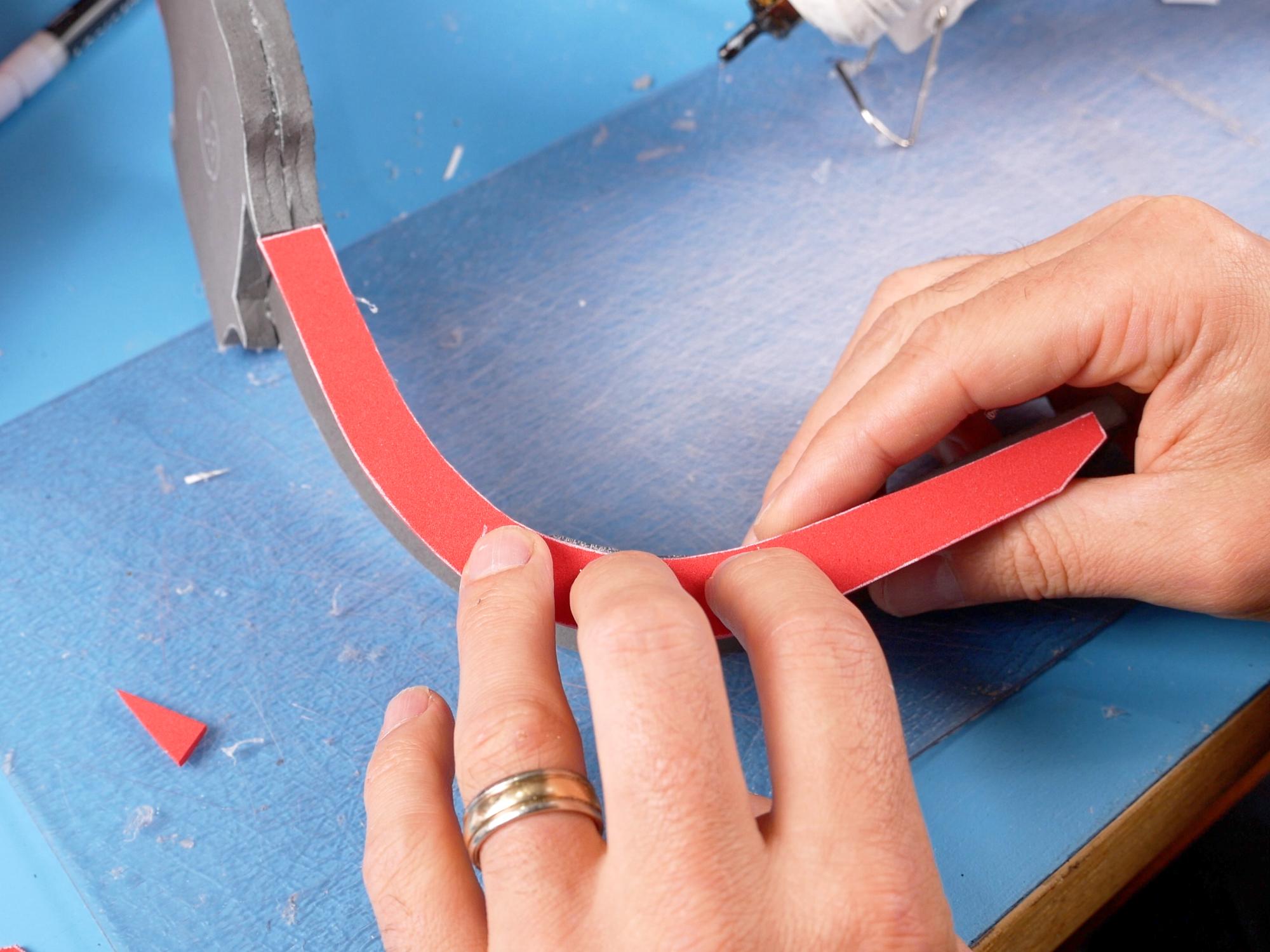
Cut a 72 cm long strip of 6 mm foam, the width of piece 45.
Cut a slight concave curve into the end so that it will butt up against the filter.
Glue the strip all the way around the bottom edge of the cyclotron pan, until it reaches the filter again.
Cut the end of the strip so it will fit against the filter. Glue 2 piece 44s side by side on top of the ramp.
Glue piece 35 on top of piece 34, and glue that stack on the speech bubble, right at the top. This makes the hose connection base.
Glue piece 38 on top of piece 37, and piece 36 on top of piece 38. This makes the Clippard base. Glue that stack a bit below the first one, just at the point that it will fit inside the edges of the speech bubble.
So Many Strips


You’ll need: Pattern pieces 5, 7, 15, 46; 2mm foam strips
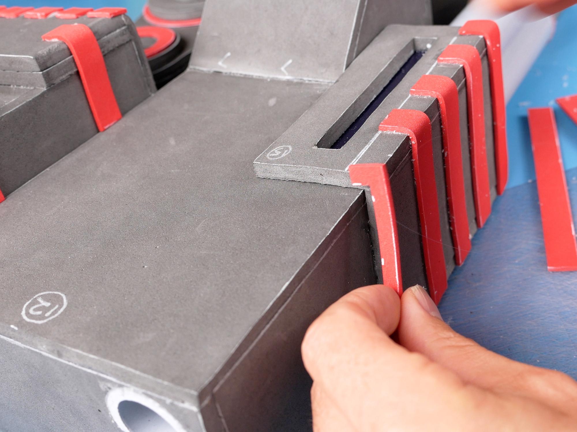
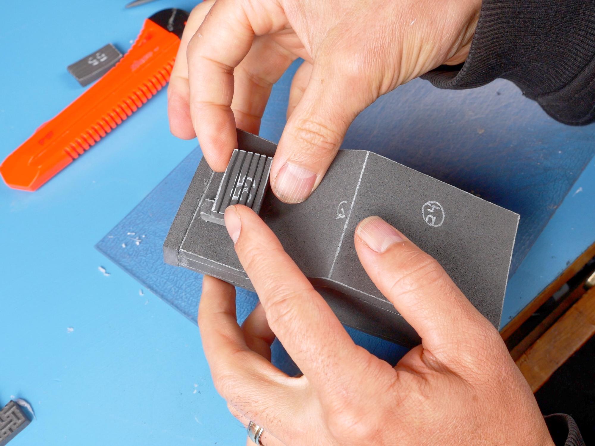
Cut a bunch of strips the width of piece 46 from 2mm thick foam. These strips will be added to the crank generator and the power cell.
Use the faint dotted lines on piece 5 to mark the placement of the strips on the crank generator big box. The top of piece 5 has the markings for the upper section of the big box, and the bottom half of piece 5 has the markings for the lower half of the big box. If you line up the dotted line on piece 46 with the top edge of the crank generator, you can use the end of that pattern piece to mark how far the strips will protrude onto the top of the box.
Once you have the strips locations marked, glue them onto the big box. Start by gluing the strip in place at the top, then bring it down around the edge and finally cut it flush with the bottom. The top strips on the upper section of the big box go all the way down to the back, but the two strips on the side of the upper section just go partway down.
On the lower section of the big box, there is just one strip centred on each side, and then the ones at the bottom are just rectangles that don’t actually go past the top edge.
Use the faint dotted lines on piece 7 to mark the location of the strips on the crank generator little box. The strips on the little box overlap farther than the ones on the big box. Make the overlap marks 3.4 cm (1.3”) from the edge. Three strips get glued down the outside edge of the little box, and then one strip on the front edge. The end of this strip meets up flush with the edge of one of the strips from the outside edge.
Use the faint dotted lines on piece 15 to mark the location of the strips on the power cell. These overlap the same amount as the ones on the big box did. The slight difference with this one is that the first strip goes on the front of the power cell and is cut flush with the top of the cell, rather than folding over onto it. The second strip goes on the side, covering the edge of the first strip as it folds over it onto the top. You may have to trim a couple millimetres off the front strip so there is enough room for it beside the PVC pipes. The back strip needs to be cut into an inverted “L” shape in order to fit around the support box. Then the last side strip can go on over top of it.
More Bits


You’ll need: Pieces 47, 48, 1" PVC conduit,
Cut a piece of 1” PVC the same length as piece 47. Sand the ends and use the abrasive pad.
Glue the PVC pipe into the depression between the two halves of the big box.
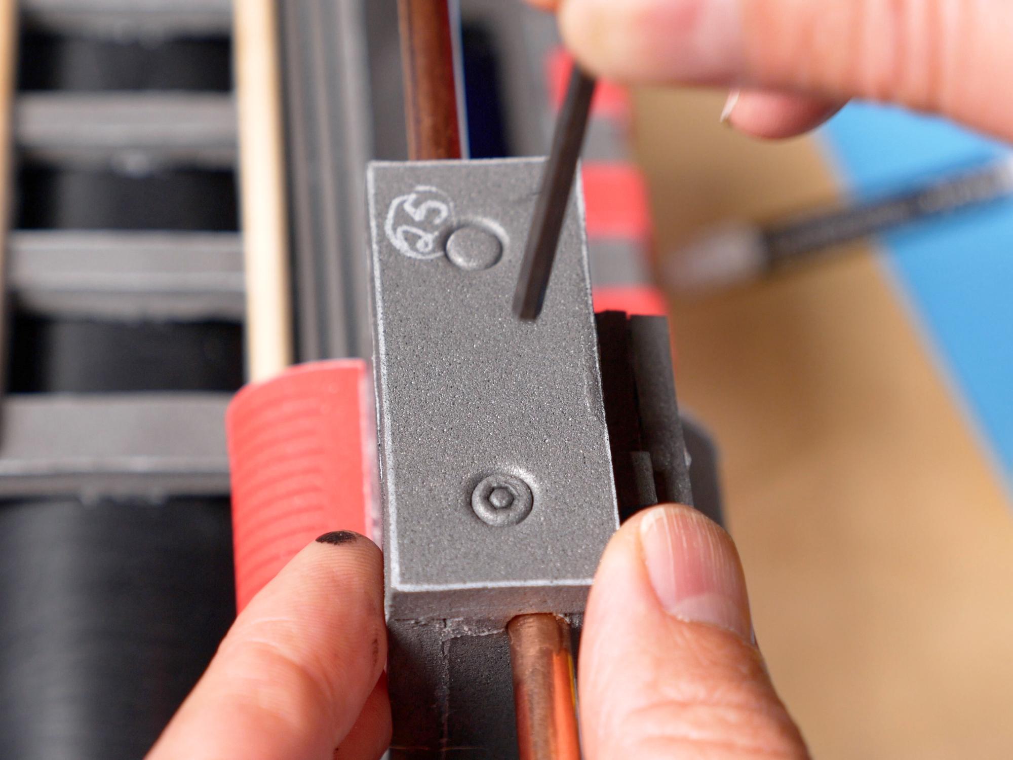
Glue piece 47 on the upper section of the big box, lined up with, and right up against the PVC pipe. Punch a 12 mm disc from 6 mm thick foam and glue it on the protruding section of piece 48.
Glue piece 48 on the upper section of the big box, centred between piece 47 and the edge strips.
The Booster


You’ll need: Pieces 39, 40, 41; 24 cm ABS pipe
Glue piece 40 on top of piece 39. Glue piece 41 on top of piece 40. Apply glue inside the flat end of the 24 cm ABS pipe, and slide the foam stack you just made into the end of the tube. Push it in until it is sitting a couple of mm lower than the edge of the pipe. You just made the booster.
Apply glue generously to the bottom of the booster as well as around the 45 degree cut. Place the booster on top of the support box and press the angled section up against the ramp. Hold it until it cools.
Speech Bubble Bottom

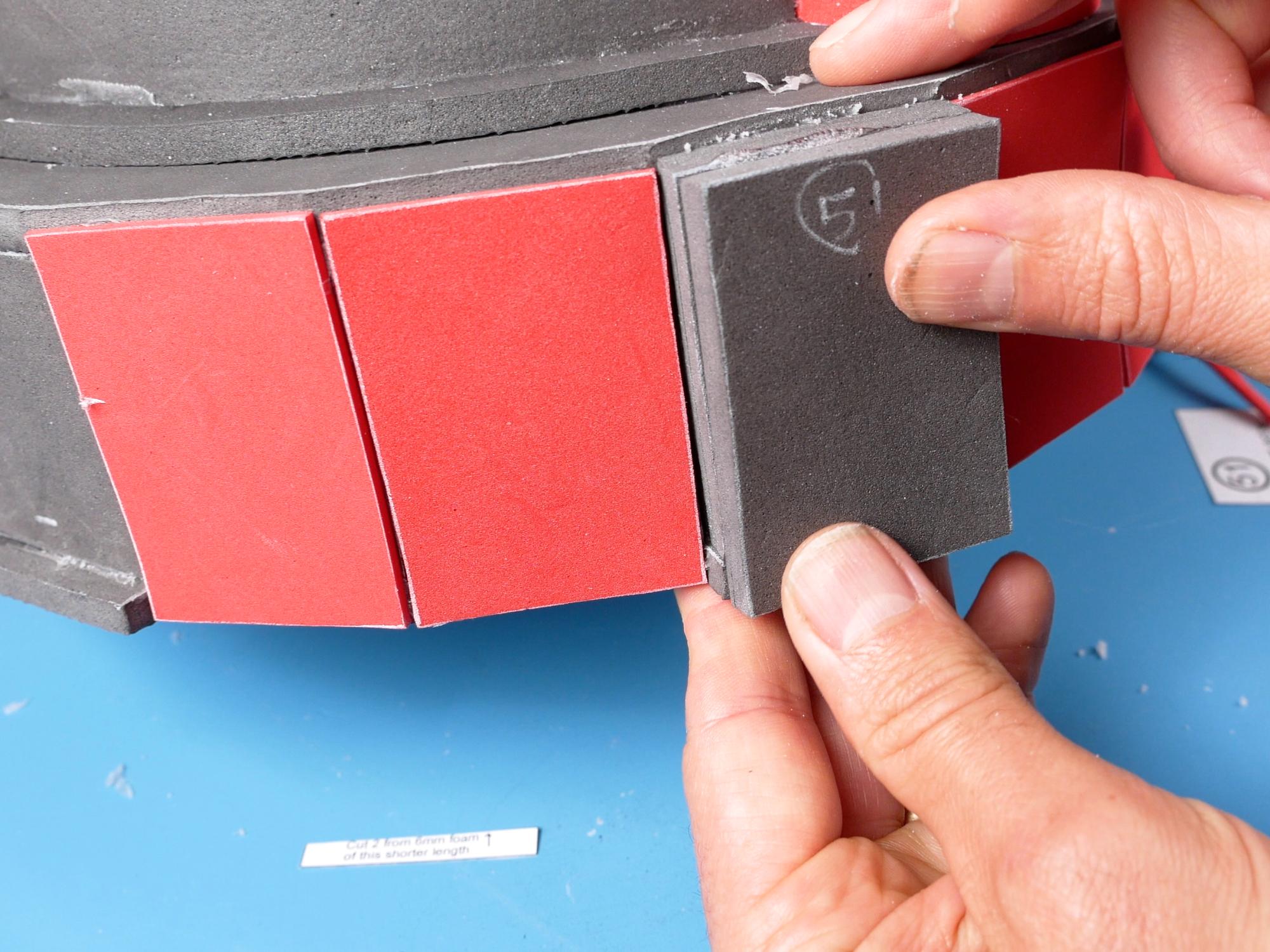


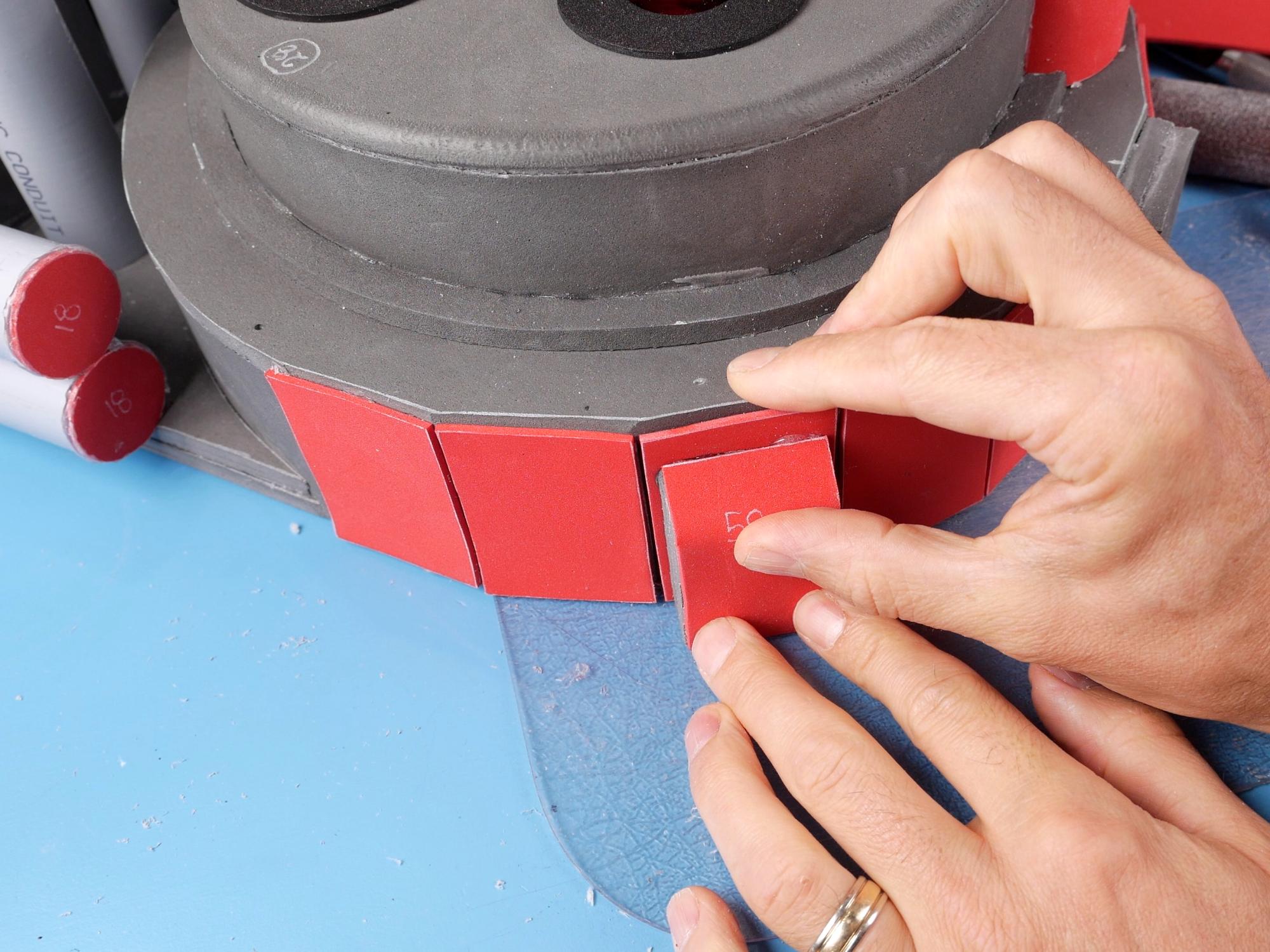
You’ll need: Pieces 51, 57, 58
You should have ten 2 mm thick piece 51s. Glue one over each flat facet at the bottom of the speech bubble. Line them up flush with the back of the pack. Their top edge should be just slightly lower than the top edge of the speech bubble. The only flat facet that doesn’t get a 2 mm thick piece 51 is the one at the bottom that has the extra tab sticking out.
There are also two 6 mm thick piece 51s. If you look at the pattern for piece 51, one of the pieces is cut shorter than the other. Glue the shorter against the speech bubble facet, so that it sits on the tab. The second, longer piece 51 gets glued over top of that piece and the tab.
Glue together two piece 57s. Cut the top edge at an angle. Glue piece 58 over the angled section and down the other side. Trim piece 58 flush at the bottom. We’ll call this the battery pack. Glue the battery pack on top of the third facet down on the left side, flush with the back of the pack.
Grain Elevator Bits


You’ll need: Pieces 52, 53, 54, 55, Grain Elevator
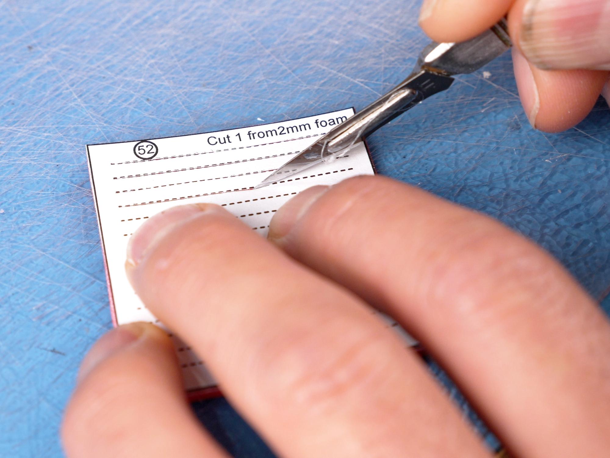
Cut score lines across piece 52, following the dotted lines. Try to make sure you don’t cut all the way through the foam when you do this.
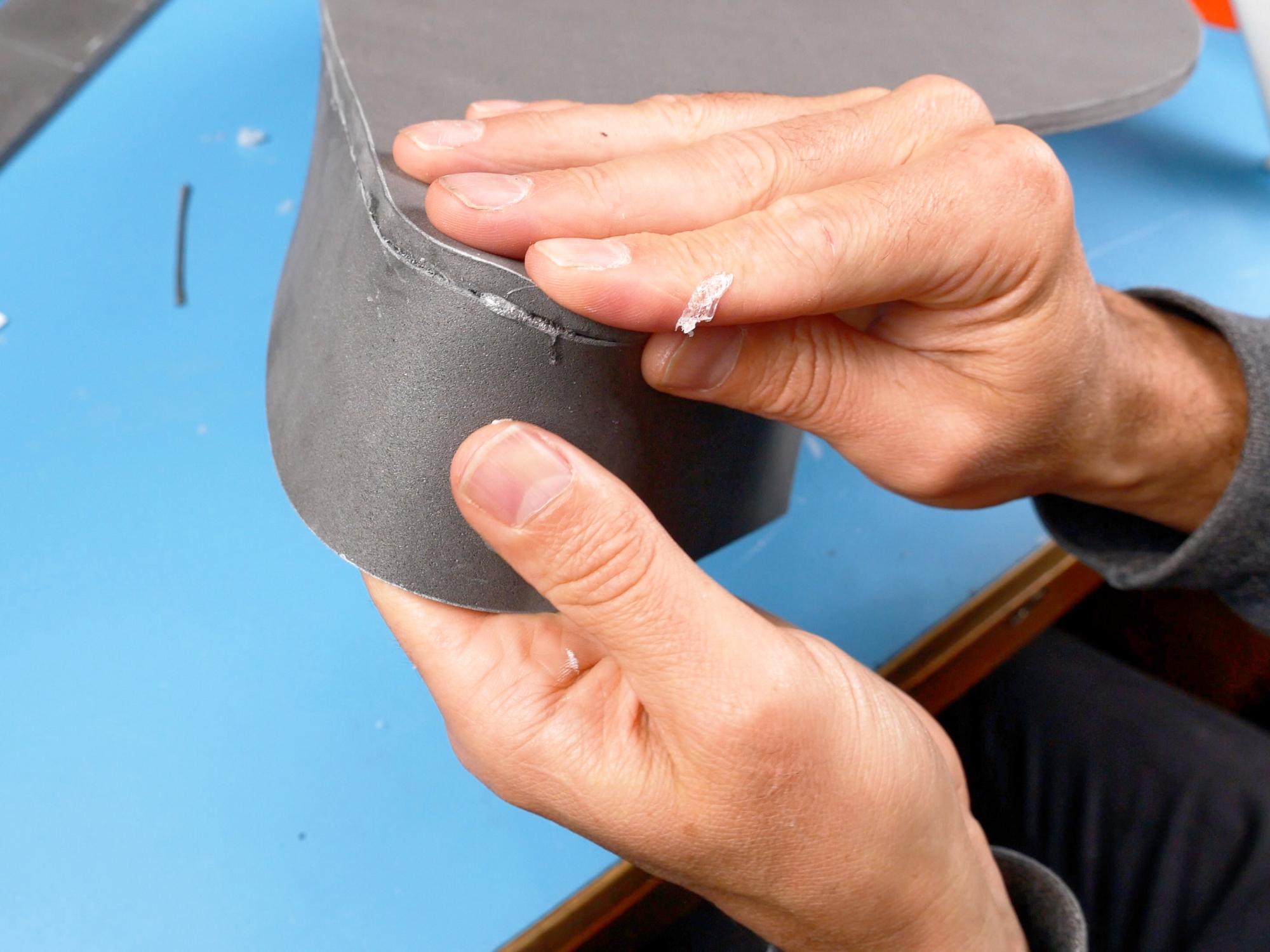
Heat piece 52 with a heat gun to open up the score lines.
Before piece 52 cools, wrap it around a thick marker to help it hold a round shape.
Glue piece 53 into each end of piece 52, giving it a dome shape. Glue that piece to the flat side of the grain elevator about 3.5 cm (1.3”) from the top.
Make 5 or 6 score lines across piece 55, going the length of it. Heat piece 55 with a heat gun to open up the score lines.
Glue piece 55 on top of piece 54. Glue this onto the other side of the grain elevator, above the angled section.
There are a couple of metal rods that go into the grain elevator. You can use a pencil and paint it with a metallic paint, or if you happen to have some copper tape, you can wrap that around your pencil for a more realistic metallic look.
On the front side of the grain elevator, at the upper right corner, cut a hole slightly smaller than your pencil. Push a full length pencil as far as you can into that hole.
On the back side of the grain elevator in the opposite top corner, make another hole and stick an 8 cm (3”) long pencil into it. Inside the grain elevator your two pencils should be side by side.
Turn the grain elevator upside down and drip some hot glue down onto the pencils far below.
Glue the grain elevator onto the upper left corner of the proton pack, with the angled section facing outward.
The Ladder


You’ll need: Ladder (piece 50), skewers
Cut three parallel V grooves running vertically on each side of the ladder.
On the backside of the ladder, cut a V groove in the top and bottom horizontal rungs, The V groove shouldn’t go all the way to the edge though. Cut a strong toothpick, or thin skewer down to fit and then glue one in each slot. This is to strengthen the ladder so it’s not flopping all over the place.
Get two slightly larger wooden dowels or skewers, (actually I have heard that the original used pencils) trim them to the length of the ladder, and cut the ends at an angle.
Glue the dowels vertically on the front of the ladder right beside the openings.
Glue the ladder to the top of the booster about 1cm below the Grain Elevator.
More Pipes


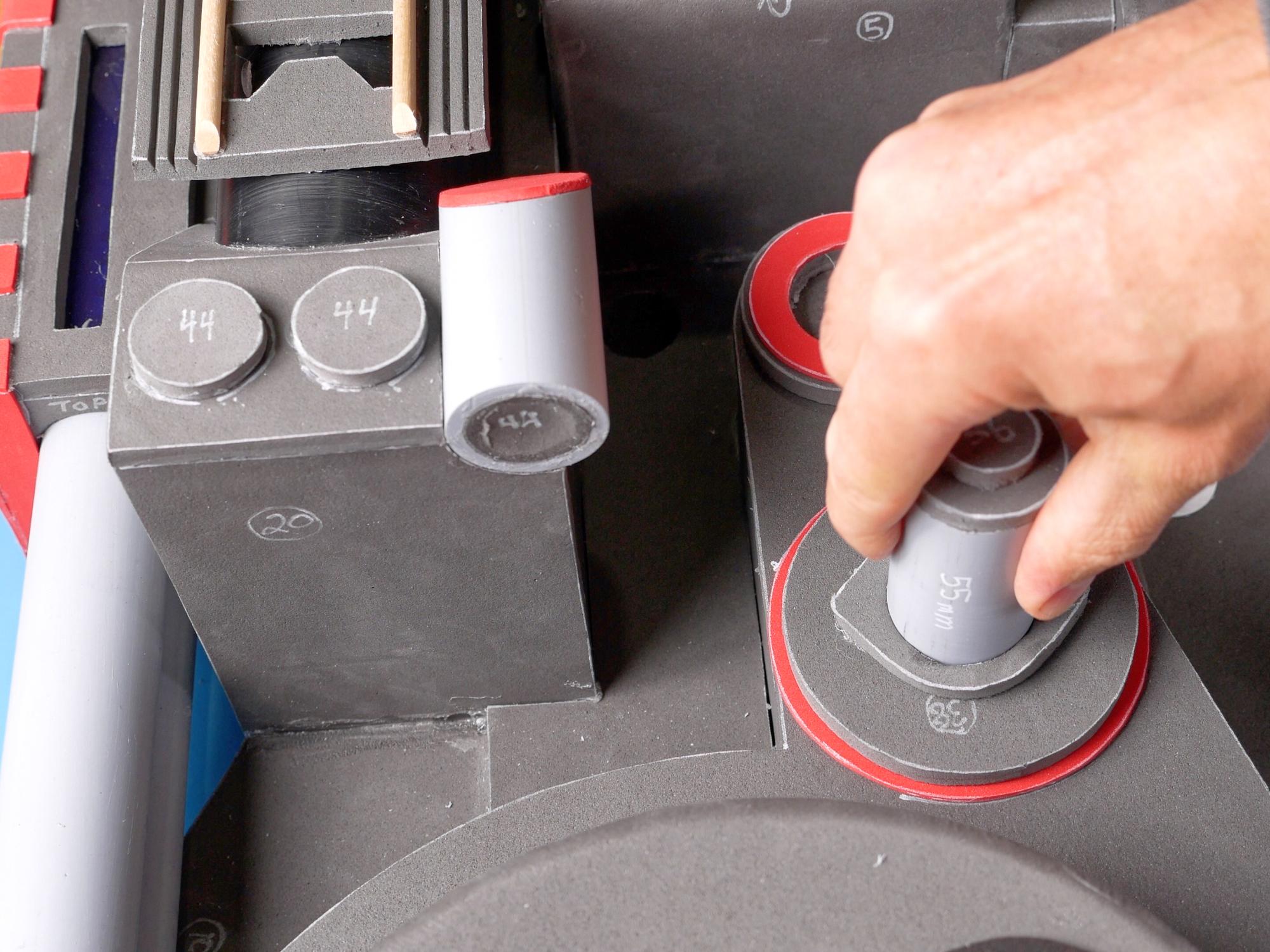


You’ll need: PVC conduit, pieces 44, 18, 56
Cut 4 PVC pipes the following lengths: • 121 mm (4.7”)
• 115 mm (4.5”)
• 70 mm (2.75”)
• 55 mm (2”)
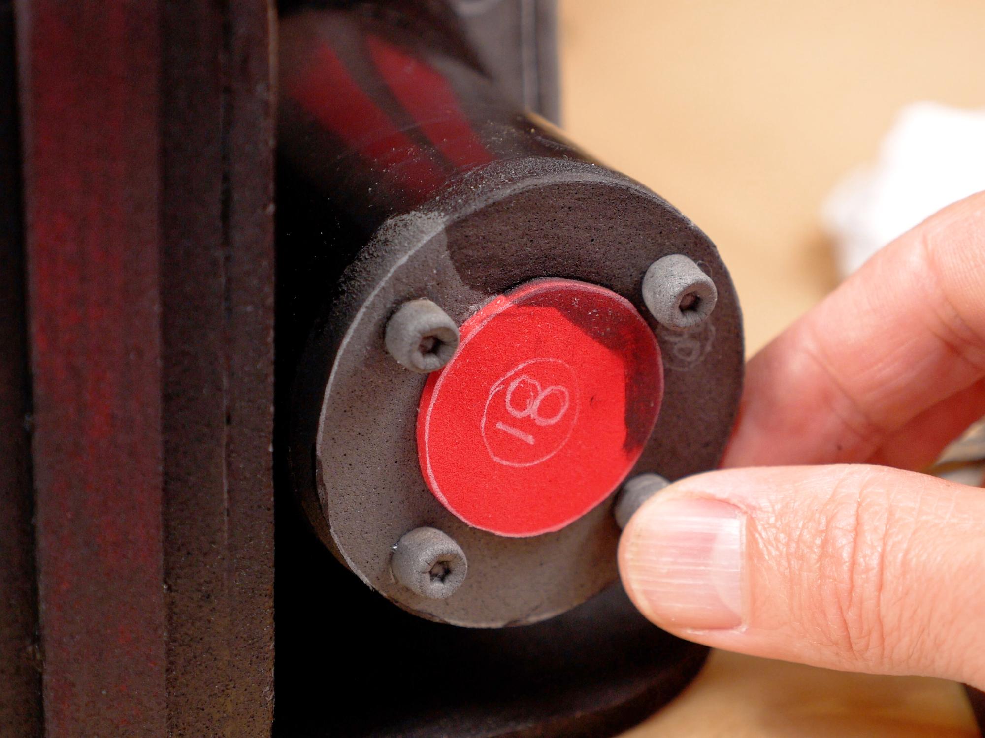
On the 115 mm pipe, glue a piece 44 into one end, and cover that with a piece 18.
On the 121 mm pipe, glue a piece 18 on one end.
Glue piece 56 on top of a 6 mm thick piece 18, and glue that on top of the 55 mm pipe. This contraption gets glued into the Clippard base which has piece 36 at the top.
The 70 mm pipe gets glued into the Hose Connection Base, just above the Clippard.
The 115 mm pipe gets glued on top of the piece that has no name, just a little bit out from the corner of the speech bubble.
The 121 mm pipe gets glued a couple millimetres to the left of the piece that has no name, and slightly lower down than the 115 mm tube.
The Cyclotron Belt


You’ll need: Pieces 42, 43, 59, 60, 61, 62, circular piece
Mark the V grooves on the backs of pieces 59 and 60.
Glue piece 59 on top of piece 60, with the longer strip of piece 59 overlapping the shorter strip of piece 60.
Cut the V groove on the back of piece 60. This cut goes all the way through piece 60 and partway through piece 59.
You want to taper the foam down from the V groove to where piece 60 ends. I found it worked best to start at the end of piece 60 and then cut angled up towards the V groove. It doesn’t have to be very pretty as it won’t really be seen.
Cut the V groove on the back of piece 59.
Check that the V grooves allow the belt to bend enough to match the side profile of piece 62. If so, apply glue into the V groove on piece 60 and hold it in place until it cools.
Glue piece 62 to the side of the belt, lining up the bottom surface of the belt with the bottom edge of piece 62. When you get up to the second V groove, glue it and hold it in place, then continue gluing piece 62 along the side.
Glue piece 62b on the other side.
The other end of the belt is simpler because it just consists of a smooth curve. Glue piece 61 along the belt edge, lining up the bottom surface of the belt with the bottom edge of piece 61. Repeat for the other side.
Glue any random circular piece of 6mm foam in the centre of the cyclotron pan. This is to support the cyclotron belt.
Hold the belt over the cyclotron pan and trace lightly around it. Now you know where you need to paint before gluing the belt in place. Once the belt is on, it will be very hard to get a paintbrush underneath there. Just don’t paint on the random circle you just glued on otherwise the glue won't adhere as well.
Glue the belt down onto the centre disk, and then onto the first facet on each side.
Make a stack of 2mm thick disks, alternating disk 42 and 43. Use seven 42s and six 43s. Glue this stack to the centre of the cyclotron belt.
Rivets, Bolts, Knobs, and Welds


It's the small details that make a build like this pop, so it's time to add a few of those.
You can make a faux welding bead with some hot glue. Just squeeze out the hot glue along an edge, trying to keep a consistent flow as you are depositing the glue. Use this technique for the two outside vertical seams on the grain elevator.
Using a pen casing or any other similar tube, press it into the foam and rotate it so that it leaves a circular impression. Do this on the top of the grain elevator (piece 25). Heat the end of a hex wrench and press it into the centre of the circles you just made to create a faux bolt end.
Using an 8mm punch, punch four discs from 6mm foam. Heat them up a little and then use the hex key again to make them into bolt heads.
Super glue the four bolt heads equally spaced around the HGA.
Make a stack of two discs 41s, draw four evenly spaced lines across the top, and cut on either side of the lines to create grooves in the disk. This goes on the outside of the grain elevator.
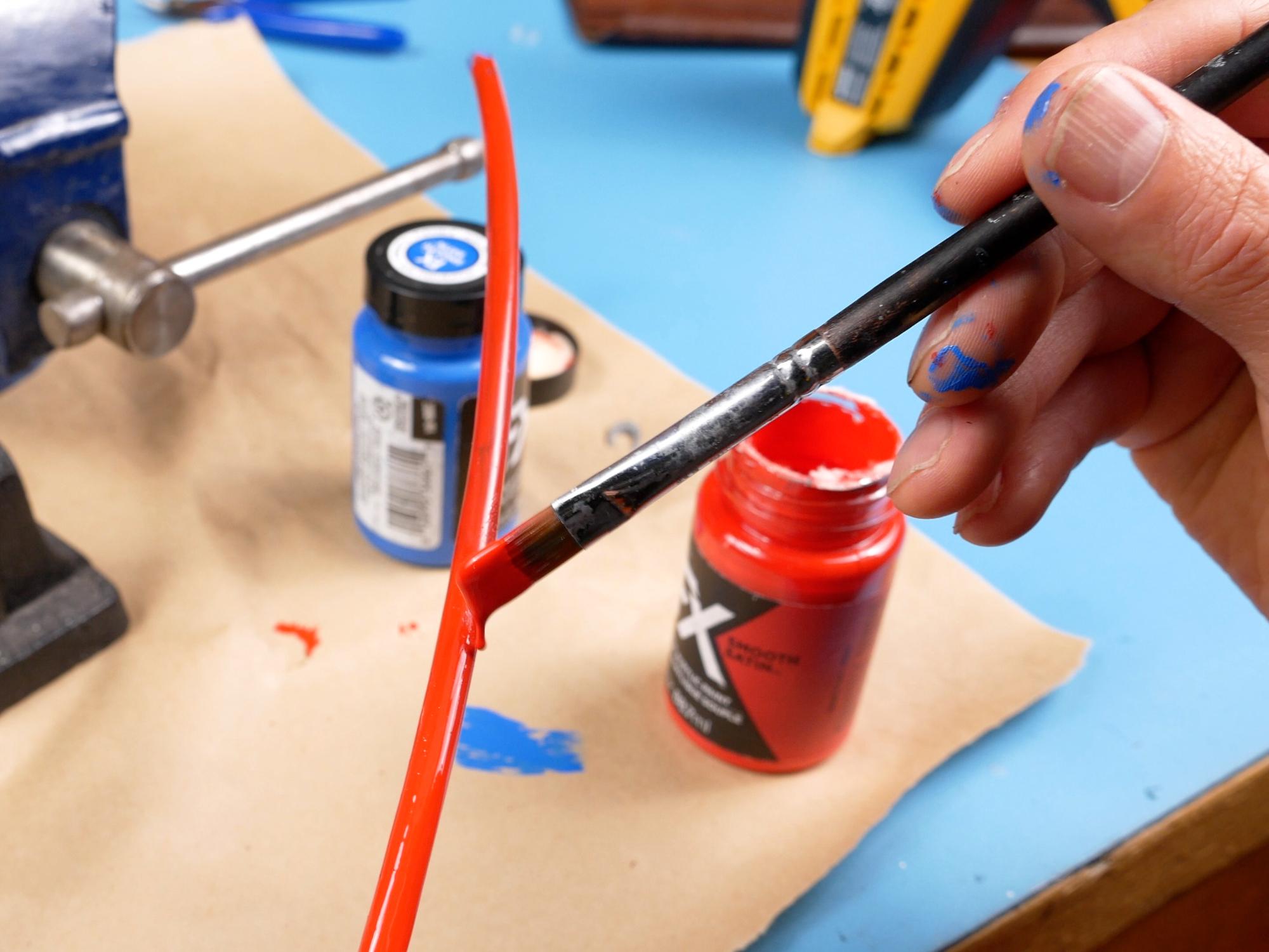
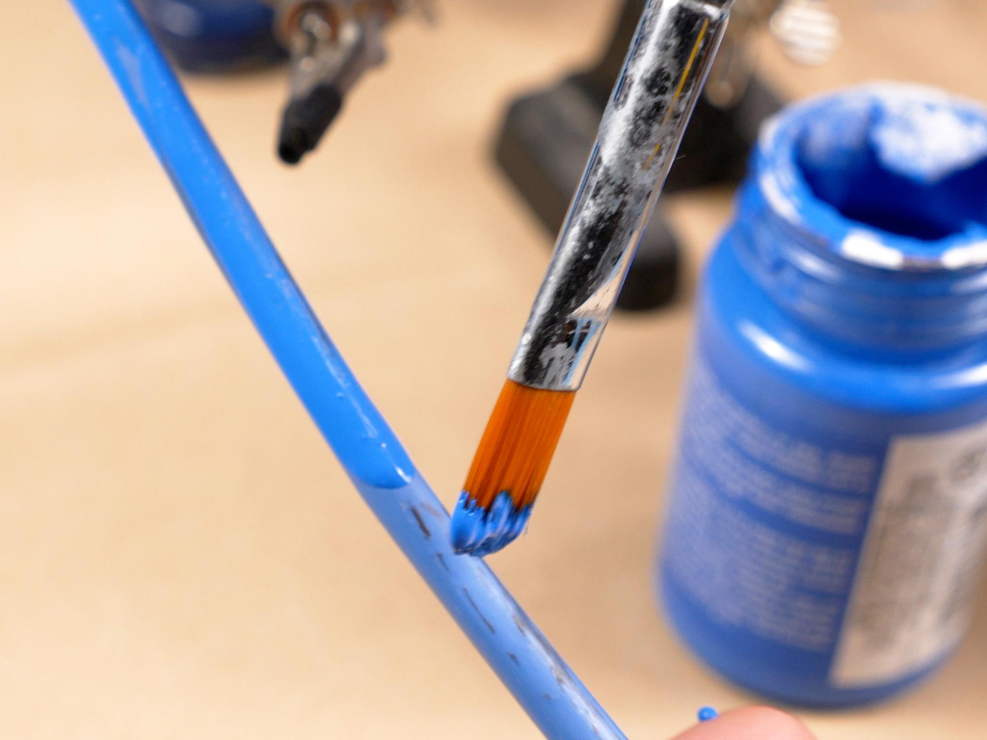
Paint It Black

There are some parts that should already be painted, but now it's time to finish the job.
I recommend giving everything at least three coats of artists acrylic paint. I know that three coats seems like overkill, but having those coats makes applying the silver antiquing much more realistic later.
Warning! Stickers

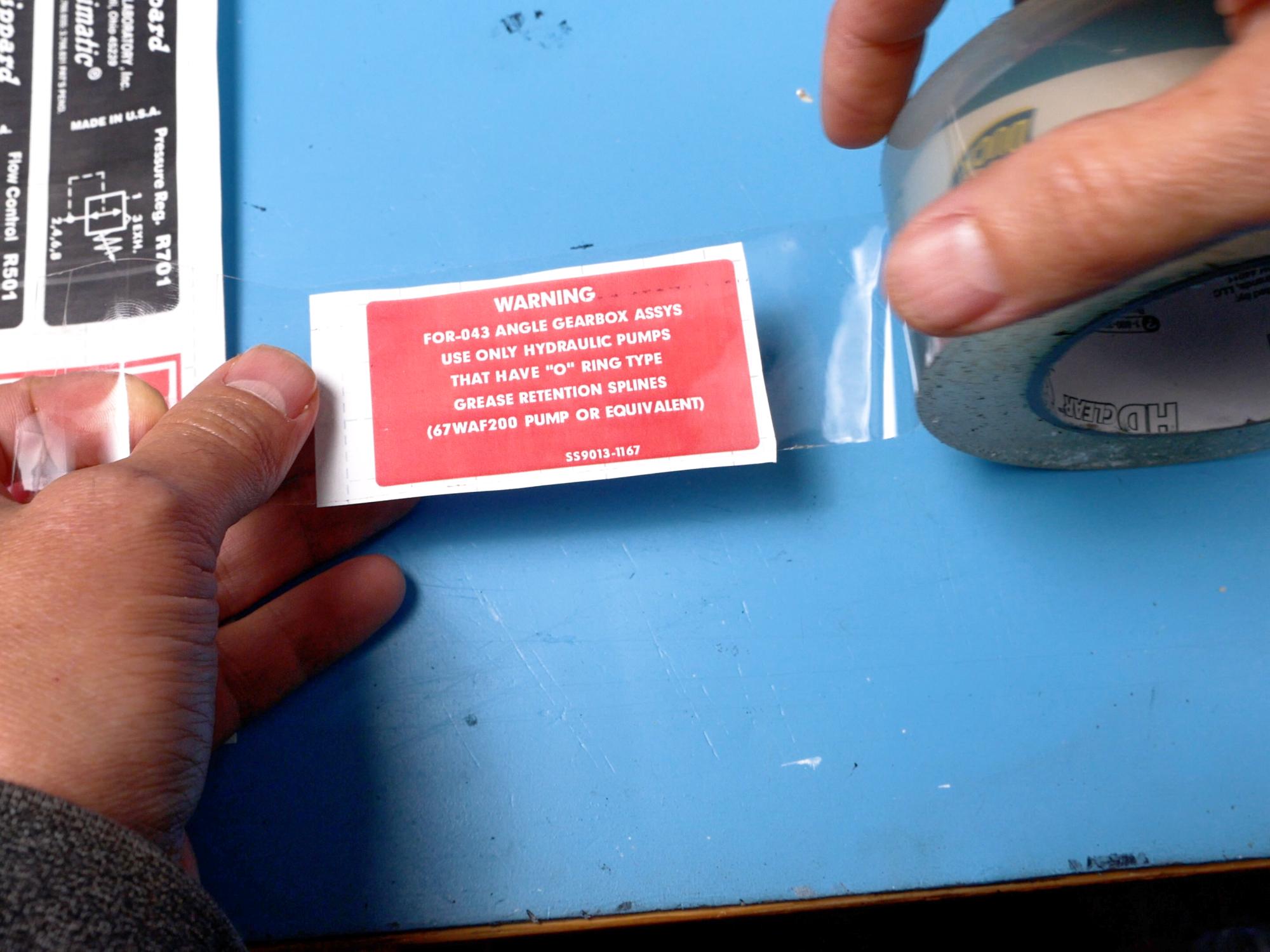


An easy way to make the stickers is with a color laser printer. Print off all the warning stickers. I found the ones I used at www.hprops.com. Thanks h-props!
Cut them out roughly, grab some nice clear packing tape and cover the front of the stickers with the tape, then you can cut through the tape and the paper right down to the edge.
Put a bit of sticky tack on the front of each sticker to hold it down, and place them face down on some scrap paper.
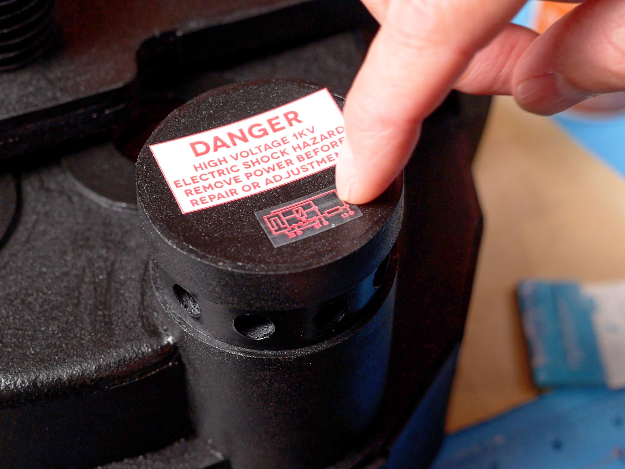
Spray some spray adhesive on the backs of the stickers. Use it according to the manufacturer's directions.
Once you've waited an appropriate amount of time, peel off your brand new stickers and stick them on the pack. Just remember to take off that sticky tack.
I will mention that before you stick on the Clippard sticker you do want to paint the top of the Clippard valve silver. It just means you don't have to paint right up to the sticker later.
Rough It Up


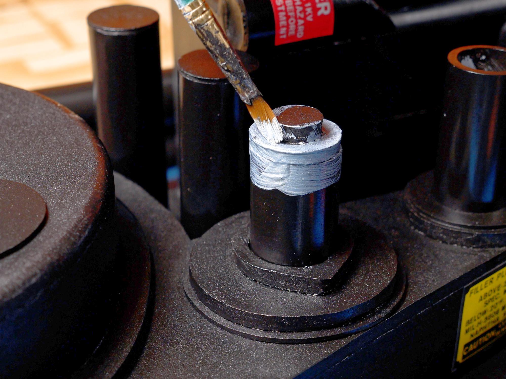
For this step, you are trying to make it look like the pack was all originally painted black and then through the wear and tear of excessive amounts of ghost hunting some of the paint got rubbed off revealing the metal underneath. The only difference is we're actually painting the silver metal colour on top instead of revealing it.
I currently use DecoArt Americana Decor metallics paints and I'm mixing half and half silver and pewter. That gives me my favourite steel-ish colour.
Put a little blob of the silver paint on some scrap cardboard.
Put on a rubber glove, and dip a finger in the paint, then rub that finger on some clean cardboard to remove most of the paint.
Now rub the small ammount of paint left on your finger onto the surfaces on the pack that would get wear and tear- edges, corners, tops of tubes- anything that would stick out a bit.
Work slowly, building up the silver colour as you go.
I find it works best to use a circular motion with your finger as you rub.
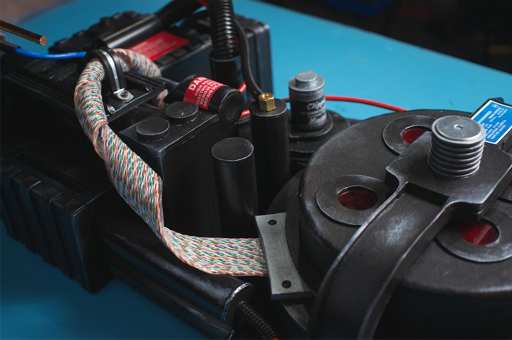
The Elusive Ribbon Cable


The trickiest part of making this pack was trying to find a decent substitute for the multicoloured ribbon cable used on the original packs. And it's kinda important to get this iconic element at least close. Here's what I ended up doing to solve the problem.
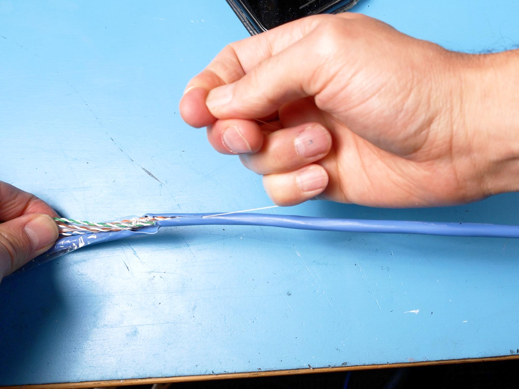
Get a length of networking cable- you probably have one from an old modem or something lying around.
Cut off a piece of networking cable 150 inches or 381 centimetres long.
Remove the jacket either with a knife or the handy little string inside.
Inside the cable you should find four sets of twisted wires and maybe a few other bits and pieces.
Cut the wires into segments 62 and a half centimetres (24.5") long.
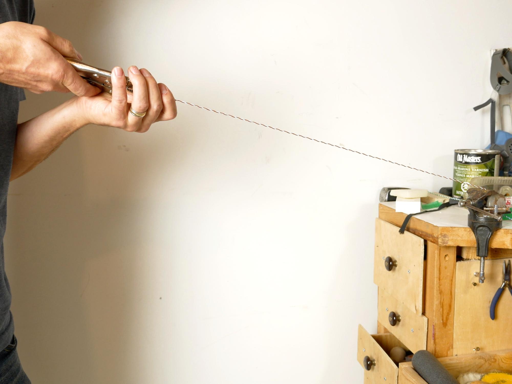
Take your wires to a vise. Put one end in the vise and hold the other end with some pliers. Pull just enough to straighten the wires out so they're easier to work with. (they are still in sets twisted together)
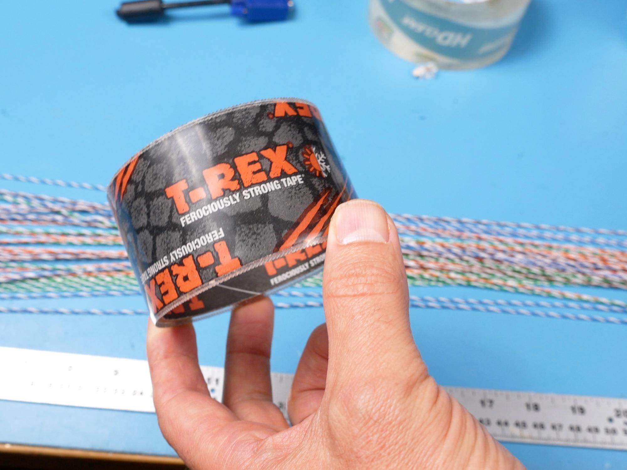
I am using T-Rex tape to hold all the wires together. This tape is kind of like a clear vinyl almost, not at all like regular packing tape. It's thicker and more flexible. I don't know if other brands would work, I haven't tried.
Use a bit of masking tape to tape down the T-Rex tape sticky side up and then start laying down your nice straight wires. Make sure to leave some room between the wire and the outside edge of the tape. On my build I should have left a little more space on the edges, so it's probably a good idea to use one less set of wires than I did.
From there just keep adding wires side by side until you've filled up the tape strip. I ended up fitting 21 sets of wires on my tape strip, however I'd probably do one less to give a little more tape on the edge.
Once all the wires are laid down, put another layer of tape over the top. Make sure the tape is able to stick to itself on both sides.
Use a heat gun and start warming up the tape. You'll notice as the tape warms up it gets soft and flexible and even maybe shrinks a little bit and that's great because you can press it down against the wires and it'll conform to their contours which helps it look just a little bit less homemade.
Once you've heated and pressed one side, flip it over and heat and repeat for the other side, and cut the ends off flush.
Attach the Elusive Ribbon Cable


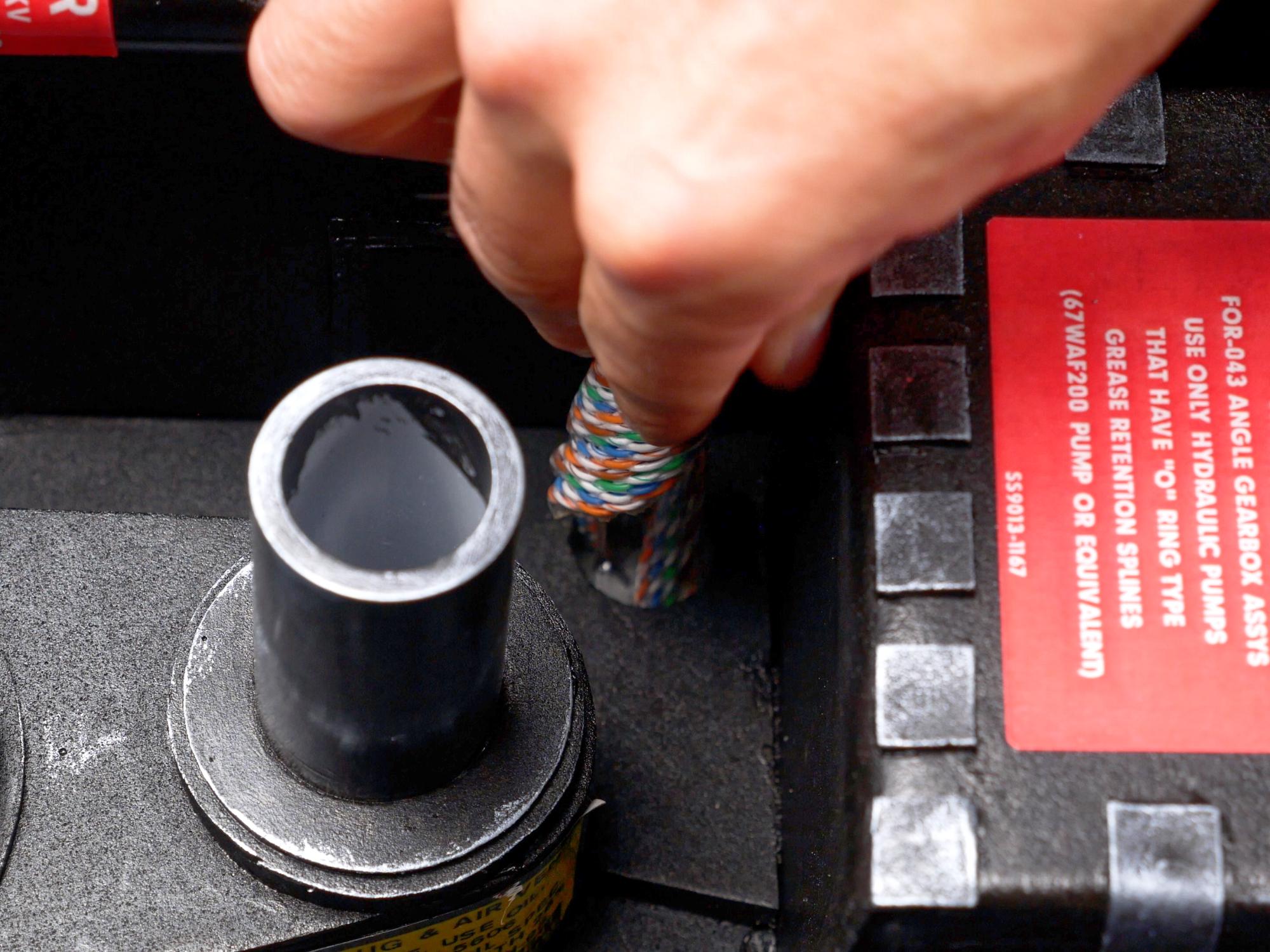

Buy a one inch rubber insulated clamp from the car parts store.
Find a small screw, drill a little hole, centered near the bottom of the ladder piece, and attach the clamp.
Twist up the ribbon cable and slide it through the clamp. The homemade ribbon cable isn't nearly as flexible as a normal ribbon cable would be which means it's harder to bend but also means it'll stay in place once you've got it bent. The tighter you twist it, the longer the cable ends up being so give it a nice tight twist.
Glue one end into the hole that's below the crank generator.
Paint piece 63 silver, mark where the ribbon cable will go, and sand away the paint underneath where the cable will be glued.
Glue the cable down and glue piece 63 on top.
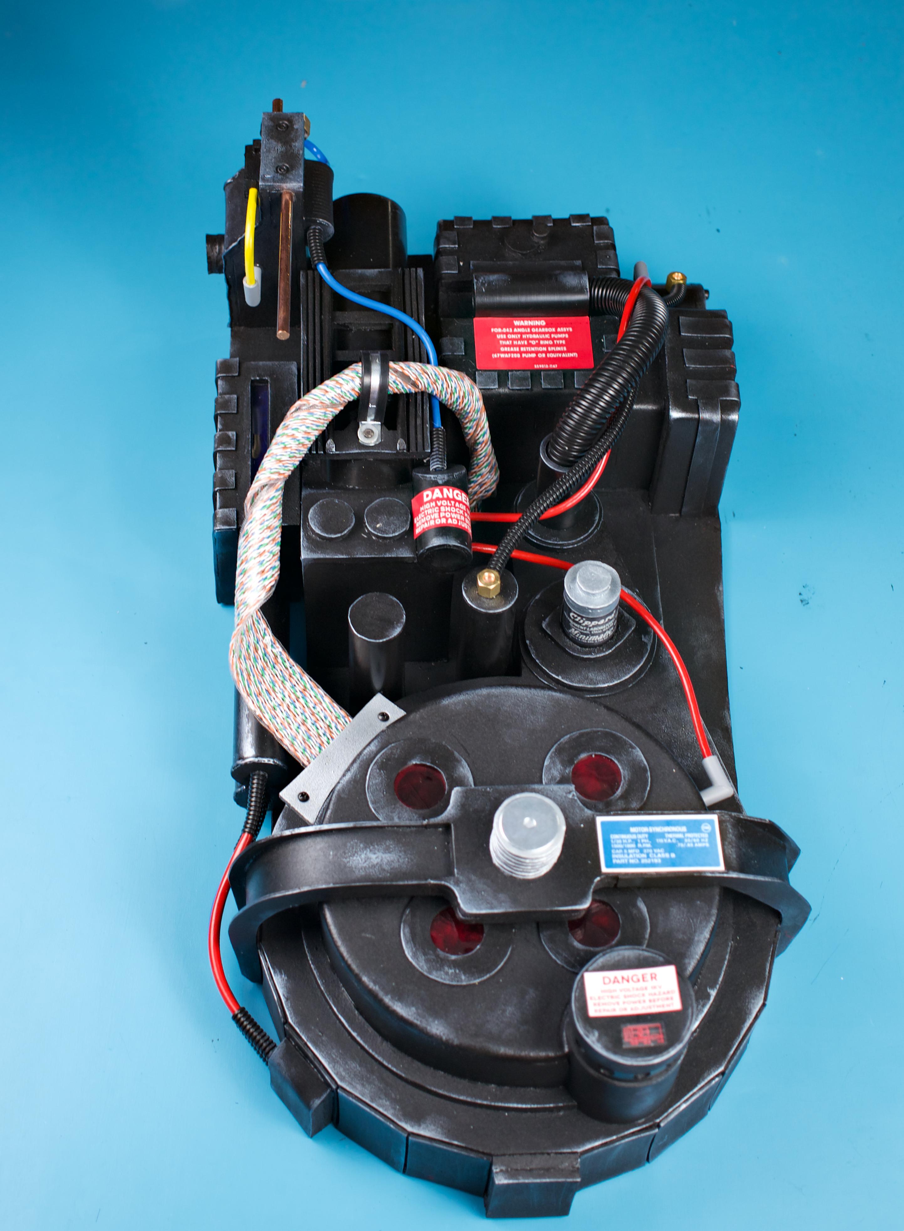
Hoses and Cables


There are lots of hoses and cables all over the pack, and I'll do my best to explain where they all go and how to connect them!
I used two different thicknesses of cables in this build. I used an old VGA cable that was 5.2mm thick for most of the cables, and a 7mm thick networking cable for a couple of short cables.
The cables on the pack are mostly blue and red, with one yellow one thrown in. As I didn't have cables in those colours, I just painted the cables I had, and it worked really well.
There are two corrugated hoses on the pack, and corrugated wire protector (split loom) in 1/4" and 3/4" sizes works great for that.
Make 2 Brass Right Angle Hose Connectors


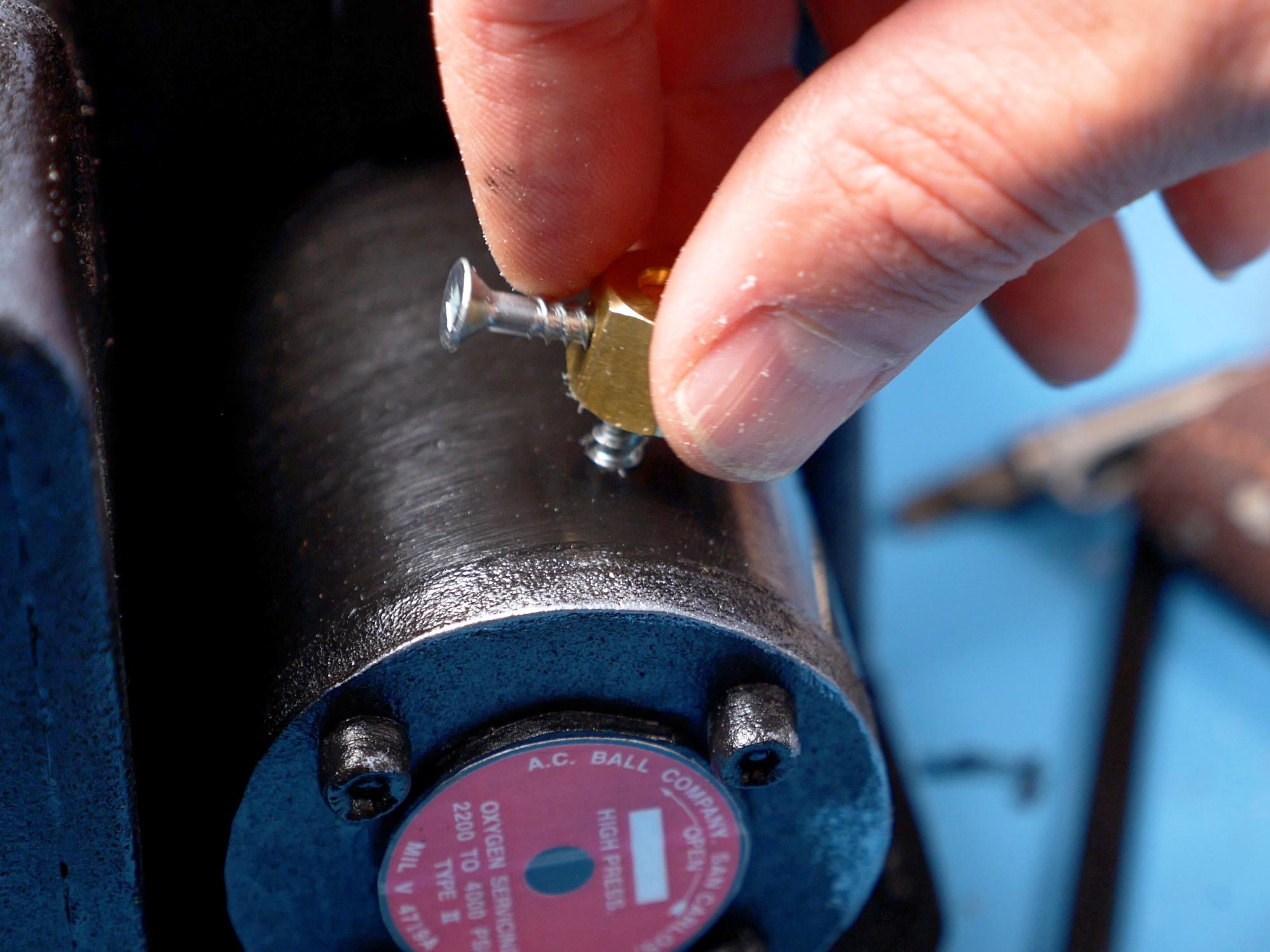

Go to the hardware store and grab five quarter inch compression nuts.
Two of the compression nuts are going to be made into right angle connectors that connect a black ribbed hose.
The problem with using the compression nuts is that they have a hole on top of them, which we don't really want for our right angle connectors. To solve that, you can punch a disk out of thin plastic that will fit inside the nut and close off that hole. I used the top of a plastic sour cream container. I covered the disk with copper tape so that it would match the compression nut. *If you don't have copper tape, you can just punch a disk from thin cardboard and paint it brass*
Push the disk into the compression nut so it closes the hole. Use a little bit of hot glue to hold the disk in place.
Find a screw where the head fits right into the grooves of the quarter inch wire protector.
Drill a hole just one size smaller than the screw, in the side of the compression nut, and then turn the screw into that hole. You might need to use some force to get the screw in, as it is basically cutting its own threads as it goes.
Mix up some two part epoxy and glue the head of a second screw into the compression nut.
Drill a hole in the ABS pipe that comes off the side of the crank generator
Drill a hole in the top of the pipe that's just to the left of the Clippard valve.
Screw the two hose connectors into the holes,
Now you can connect the two right angle nuts by cutting a 33.5cm length of wire protector hose and sliding it over the screws to keep it in place.
Grey Elbows


There are also some grey plastic elbow fittings on the pack. Unfortunately I couldn't find anything quite right, so I had to construct some. I used 10mm thick plumbing pipe that I found in my junk box for this.
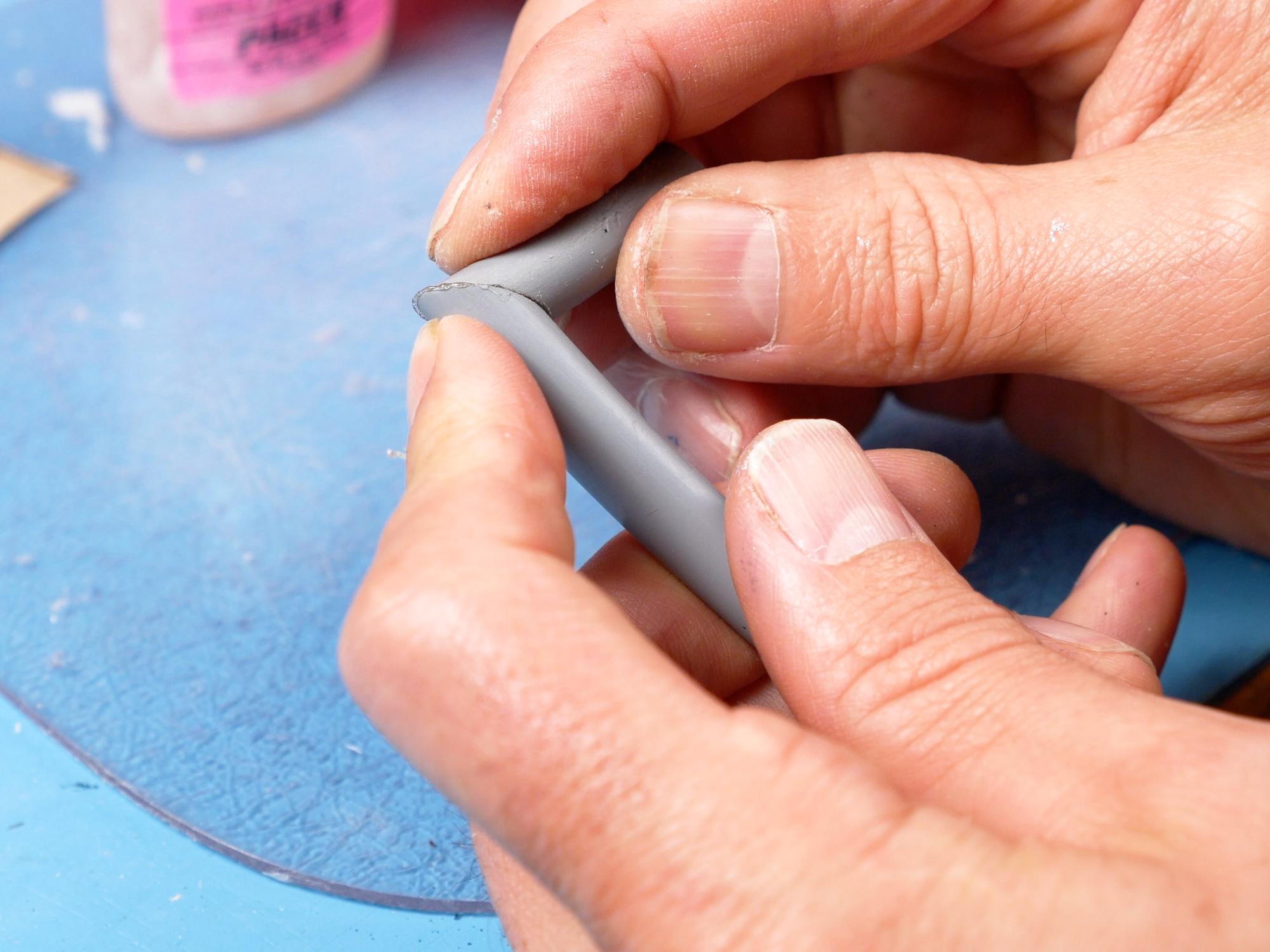
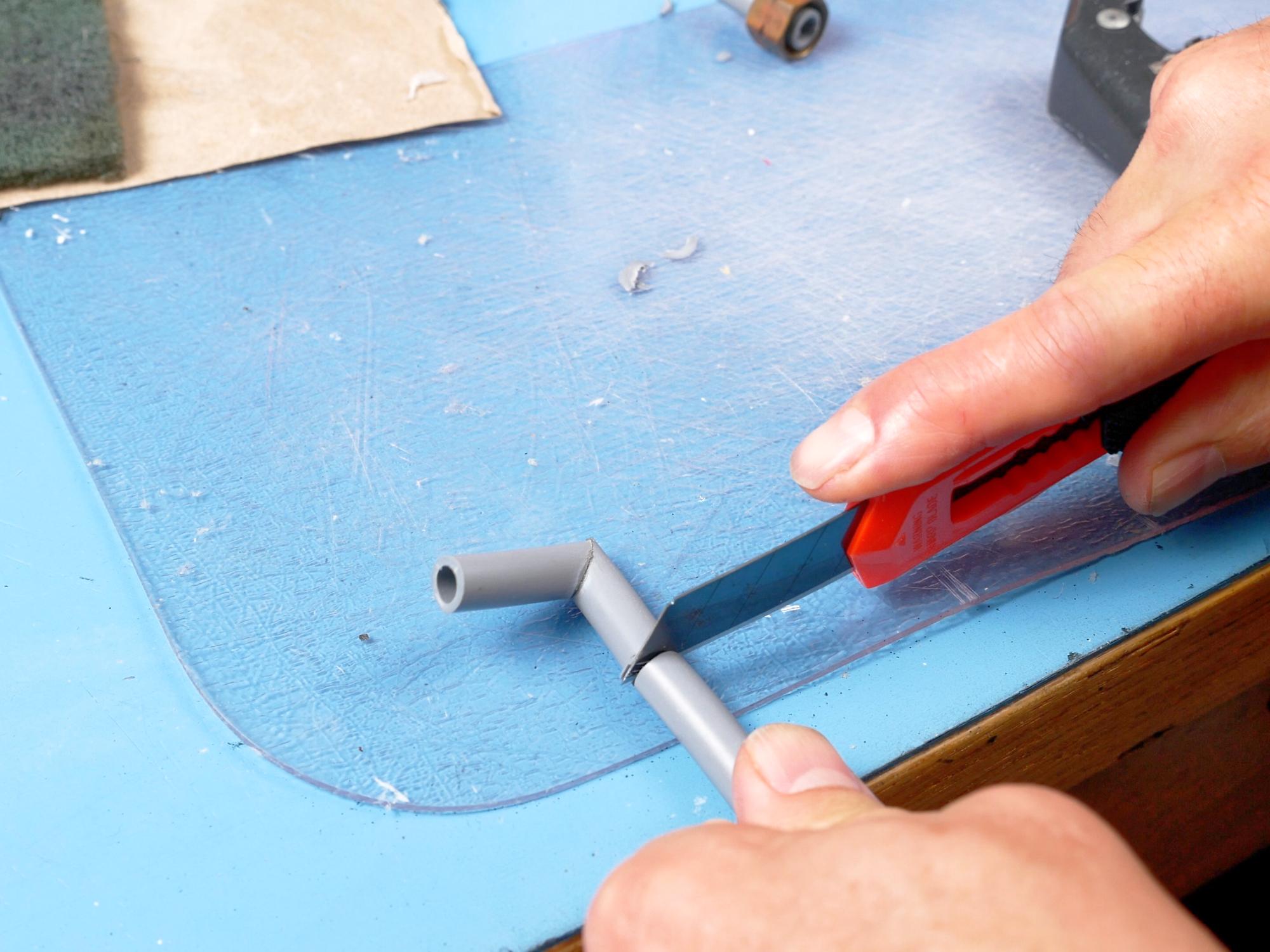
Cut the pipe at a 45 degree angle and sand it nice and flat,
Super glue the two halves together on the angled cut to make an elbow.
Trim it down to size- I made each pipe about 2.5 cm from outside corner to end.
Sand the point off the corner.
Squeeze hot glue into the pipe to give some added strength.
Whittle a sharp pointy stick out of a skewer or dowel.
Cut it off and glue it in one end of the elbow. You should end up with a 90 degree elbow with a pointy stick coming out of one side of the elbow.
Repeat these steps to make two more elbows.
Elbow Glue


Drill holes the right size for the sticks on the grey elbows: on the lower side of the grain elevator, on top of the HGA, and on the right side of the cyclotron pan.
Spread a little two part epoxy on the sticks, and glue the elbows in place.
One More Brass Right Angle


There is another right angle fitting, but this time, instead of connecting to a corrugated hoes, it connects to one of the 5mm cables.
Make it the same way as you made the first two brass fittings, except, instead of a screw going into the hole you drill on the side, one of the cables is going to go in the hole. This means you will need to drill a hole that fits whatever cable diameter you are using.
It gets screwed into the top side of the grain elevator right near the copper pencil. The hole should be facing down.
Large Hose


Cut a 37cm length of 3/4" corrugated wire connector (split loom)
Feed it into the upright pipe that's below the crank generator, then run it into the horizontal pipe that's on top of the crank generator.
If there is excess split loom that comes out the other side of the horizontal pipe, trim it off.
Glue the split loom into place with hot glue.
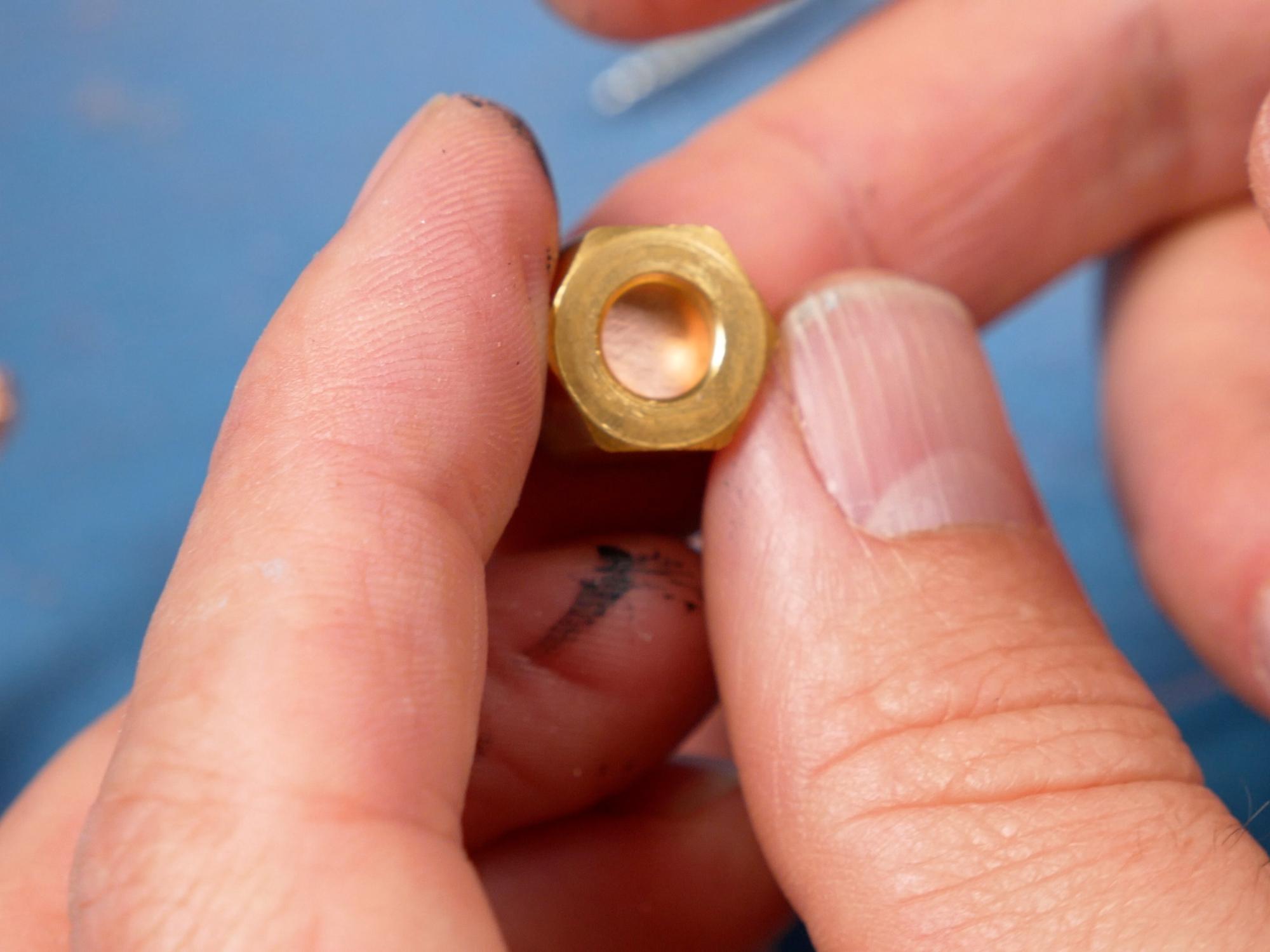
Last Nuts


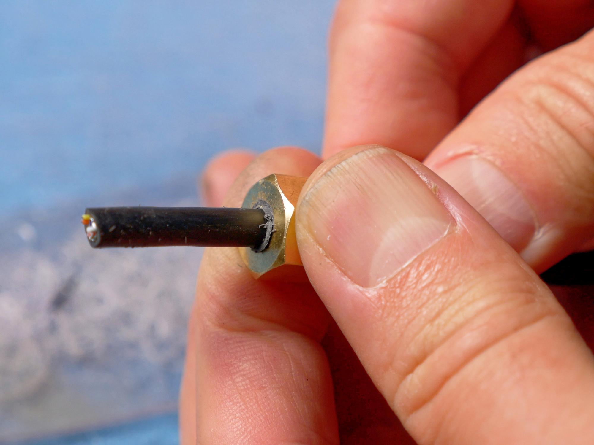
Our last two compression nuts will have cables coming out the hole that's already in the nut. The only problem is that hole will likely be a little too large for the cable, so we need to make an insert to hold everything tight.
Punch two disks from 6mm foam that will fit inside the compression nuts.
Use 2 part epoxy to glue the foam disks into the compression nuts.
Once the epoxy has cured, use a smaller punch to punch a hole through the foam disk.
Make sure the punch is small enough to create a tight fit for your cable.
Red Cables (5mm)


Drill two holes, side by side, under the pipe with the slanted end on the ramp piece.
Feed a red 5mm cable into each of the straight connection brass nuts you made in the previous step.
The upper red wire will wind around the large split loom, and end up getting glued into the grey elbow that's attached to the HGA.
The lower red wire will head down to the grey elbow on the side of the cyclotron pan.
Blue and Yellow Cables (5mm)
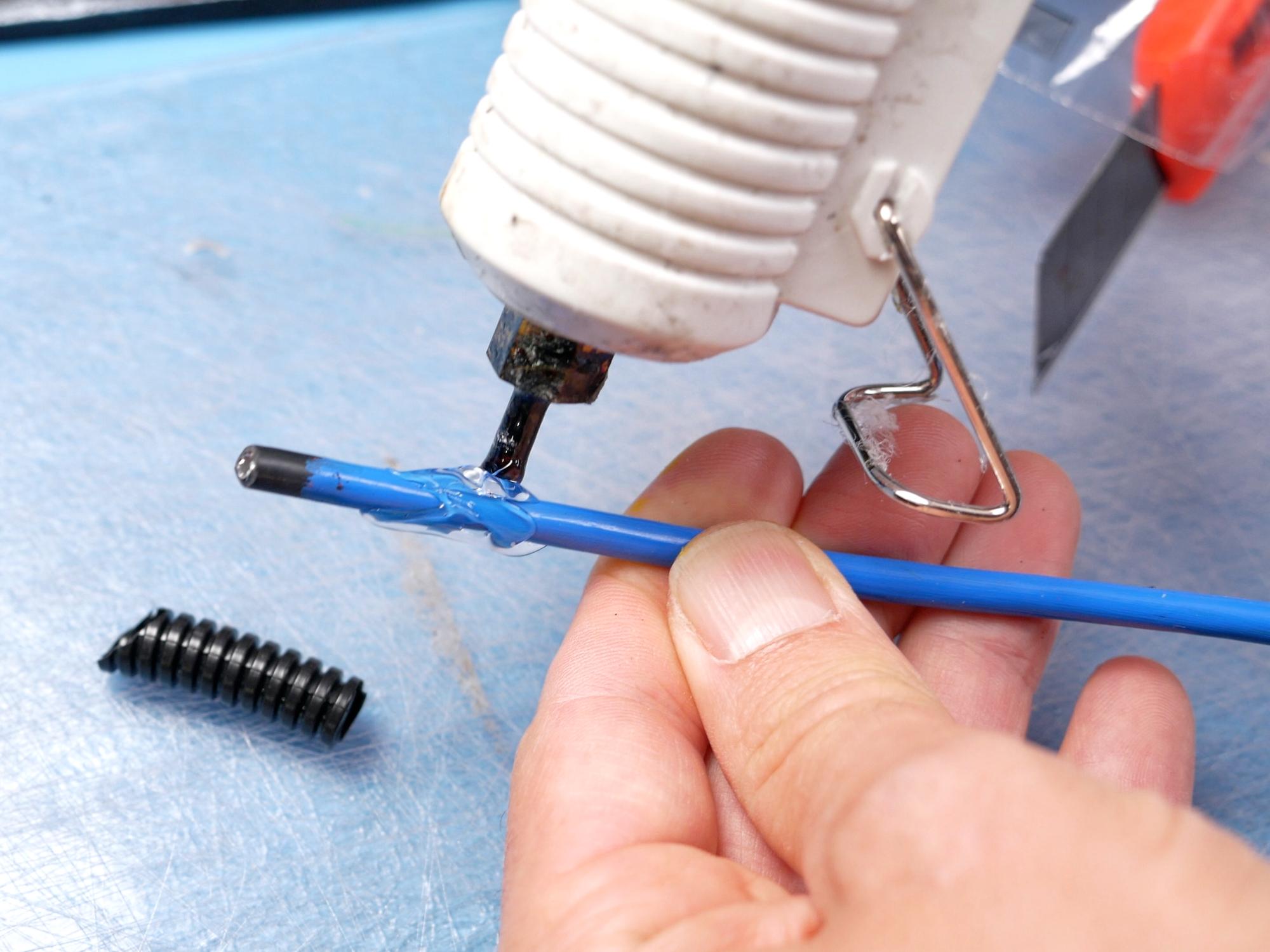


Some of the cables are made with a strain relief segment on their ends. We are going to fake this with some more of the 1/4" split loom.
The first blue cable is going into the angled end of the pipe on the ramp. Cut the split loom off at an angle on one end to match the ramp angle, and flat on the other with a total length of about 3.5 cm.
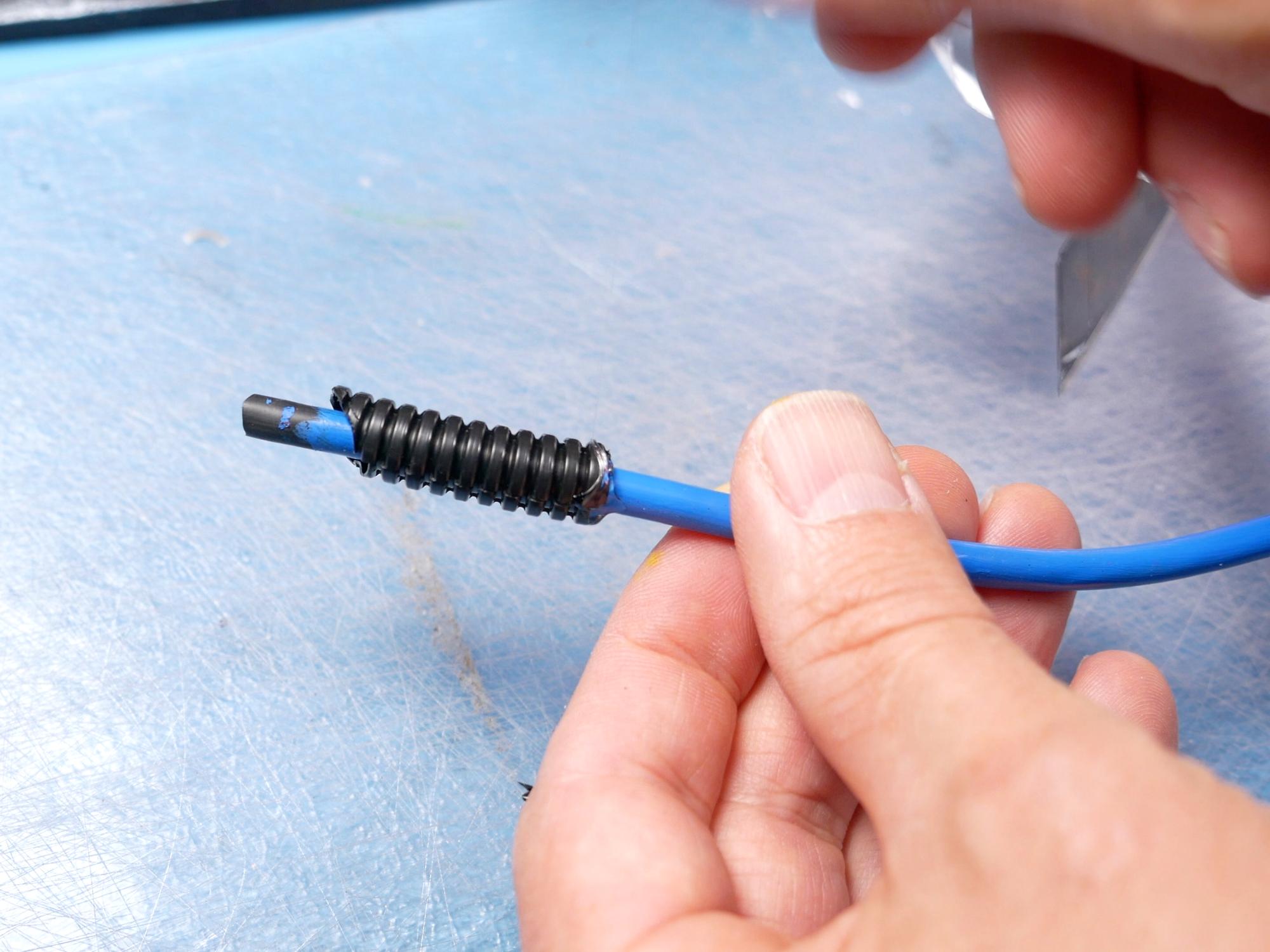
Apply hot glue to the cable and then slide the split loom on, making sure a few cm of cable comes past the angled end.
Drill a hole in the centre of the angled face on the pipe, and glue the cable in, pushing it in until the split loom makes contact.
The other end of that cable goes up to the bottom side of the half dome that's on the grain elevator. It also gets a section of strain relief.
A shorter blue cable (no strain relief) comes out of the top of the half dome and goes to the brass compression nut near the top of the grain elevator.
A short yellow cable goes from the grey elbow on the lower section of the grain elevator, up to the side of piece 55
Red and Blue Cables (7mm)


From the 7mm thick cable, cut two 27cm lengths. One will be painted red, and the other blue.
These will also get 1/4" split loom as strain relief on each end. Check that the cables are the right length to go from the bottom of the two pipes coming out of the power cell, to the side of piece 58.
Glue the cables in place with the red one as the upper and the blue one lower.
Final Details


Add a couple of screws to the silver plate that goes over the ribbon cable.
Add some screws to the side of the cyclotron belt.
Add a large fender washer to the top of the disk stack on the top of the cyclotron belt.
You Just Made a Proton Pack!
Congratulate yourself for a job well done. You have just joined the ranks of lightweight-but-awesome proton pack owners!
Things to Consider


This tutorial only covers making the pack itself, not how to attach it to a frame with straps so you can put it on your back. I do have a video showing how to make an "Alice Pack" frame out of PVC which works great with the proton pack. If you are planning to put your pack on a frame, it is a smart idea to figure out some attachment points on the back of the proton pack and reinforce those from the inside of the pack with a few wood blocks glued in. This is also a good idea if you are planning to make a mounting for a proton wand on the side of the pack. This reinforcement is best done before you glue the back piece to the pack.
Another option for a stronger pack is to make the back piece out of some thin plywood. Then you can easily attach it to a pack frame with some screws.
Thanks for hanging out with me!
If you'd like to see more of my projects you can find me here:
Subscribe to my YouTube Channel
Follow me on Instagram
Check out my Pattern Shop