DIY Handheld Game Boy Using ESP32-C3 Super Mini
by CrazyScience in Circuits > Microcontrollers
221 Views, 2 Favorites, 0 Comments
DIY Handheld Game Boy Using ESP32-C3 Super Mini
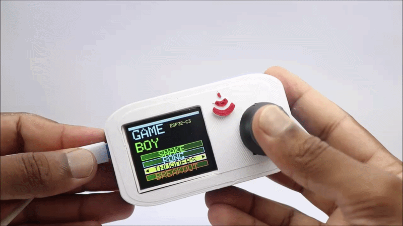
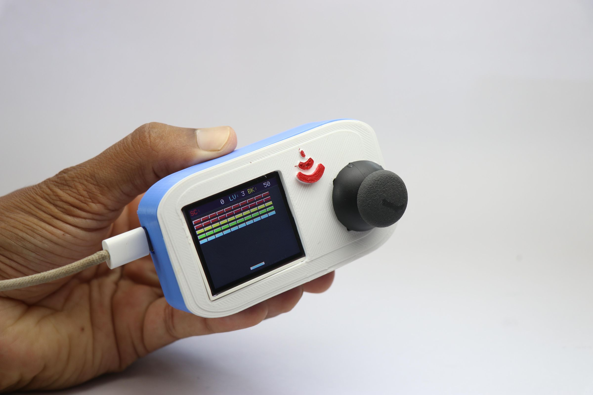
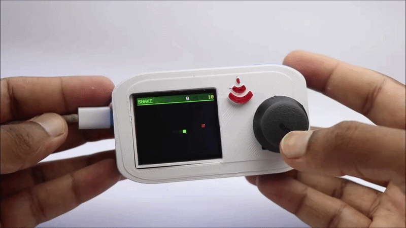
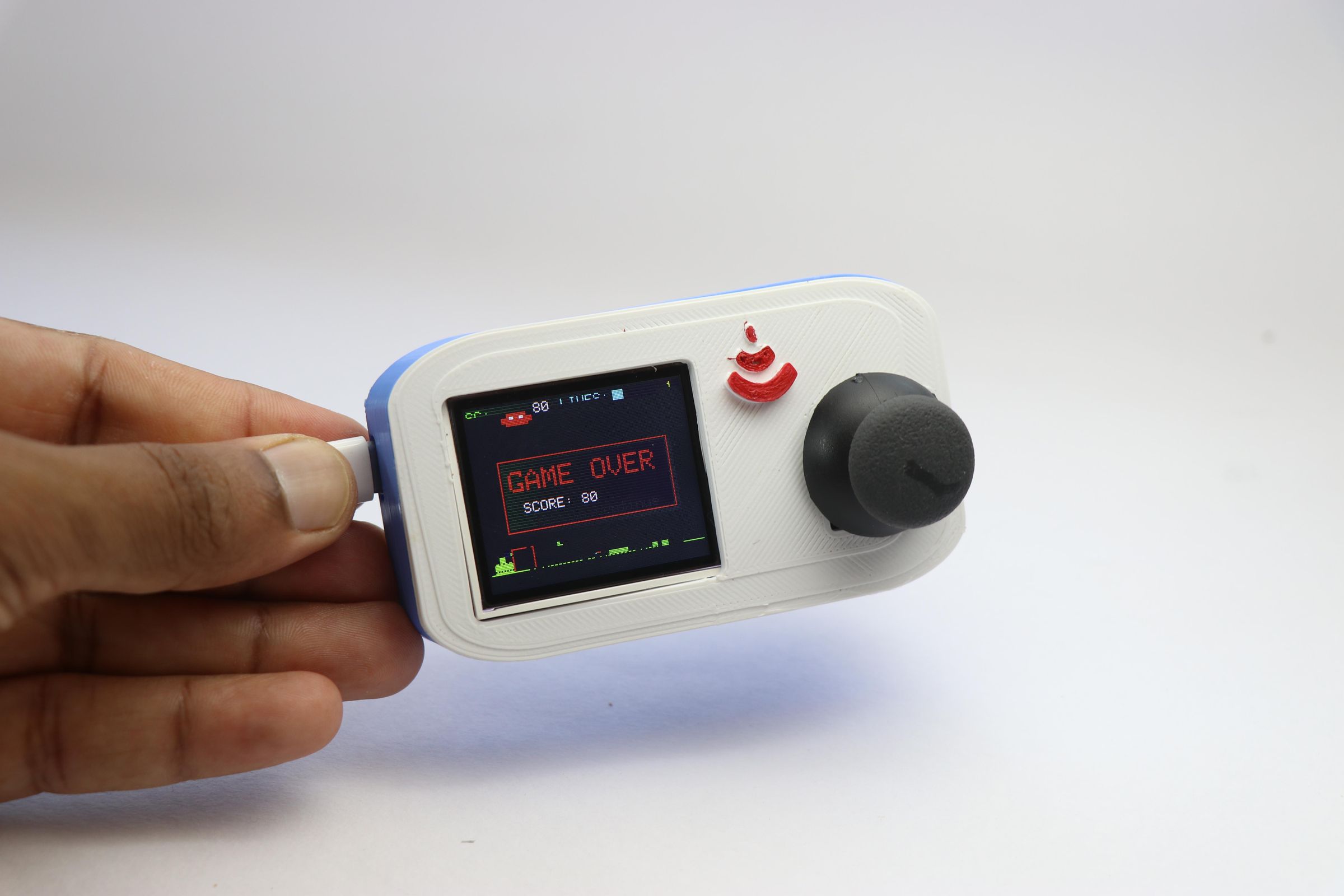
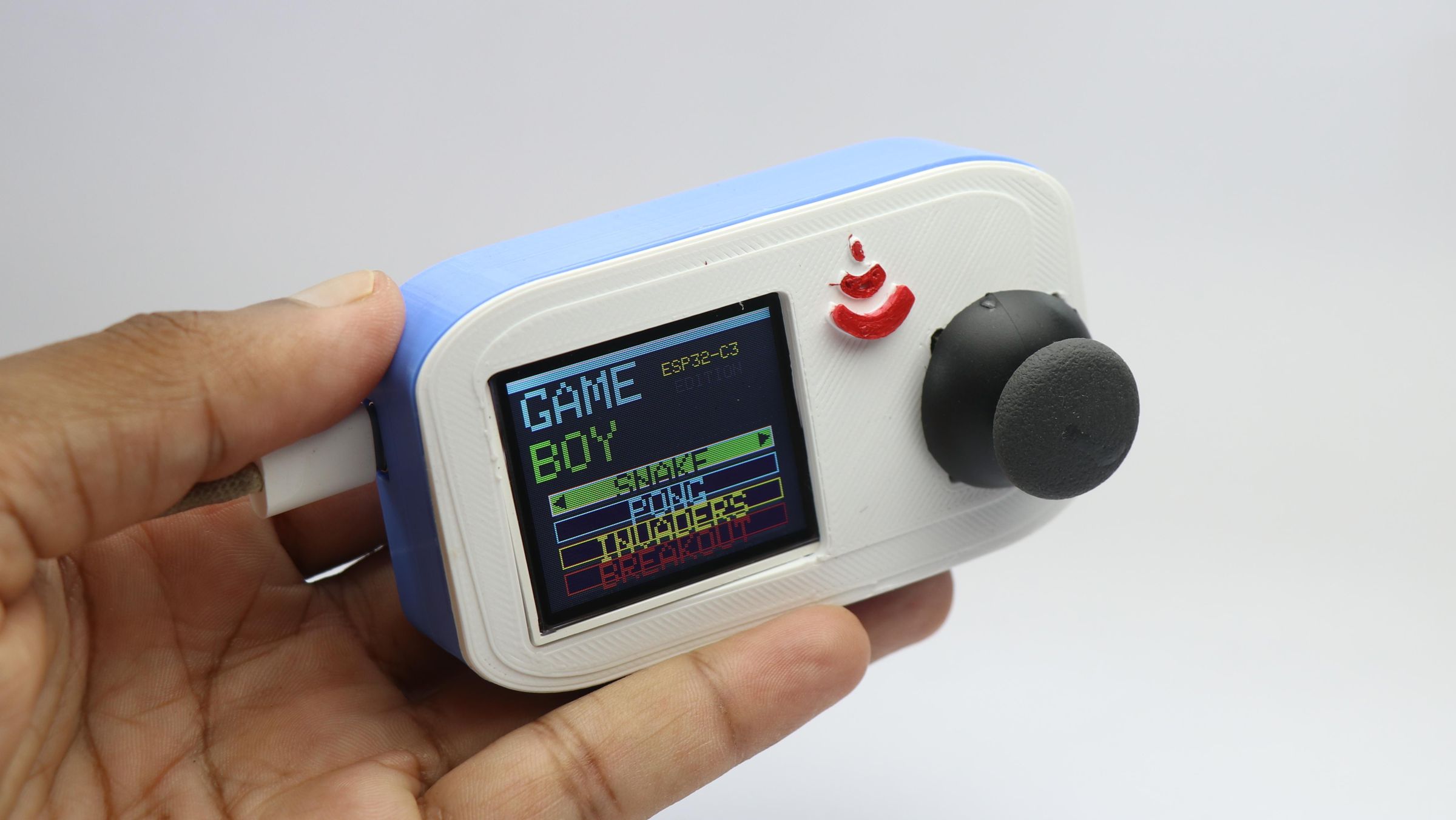
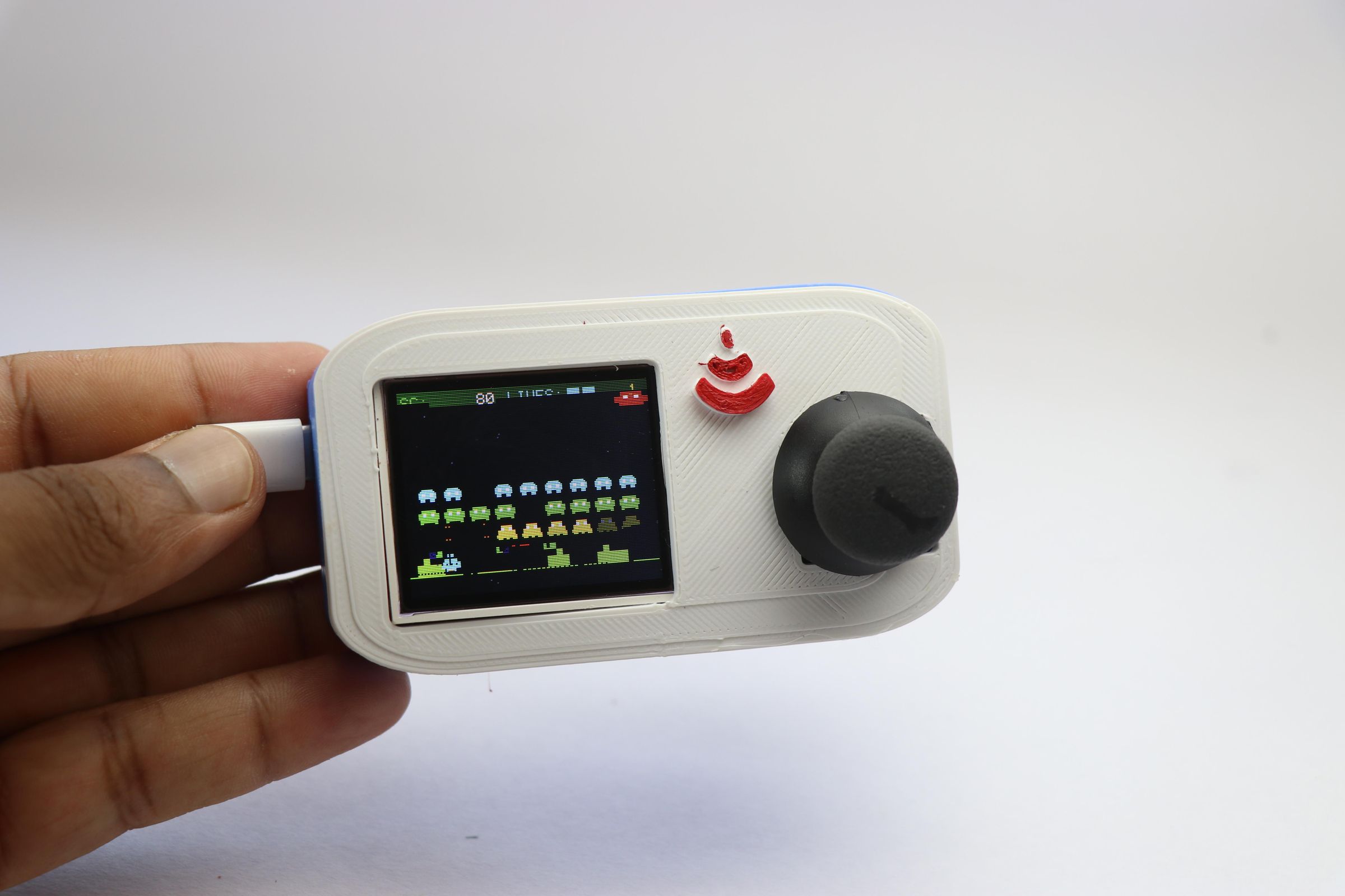
Hello friends, thanks for showing interest in this instructables and we will see how you can make your own handheld game boy at home using 3d printed parts and a 3SP32 C3 Super Mini board.
Before jumping into the build, let me tell you what motivated me to build this project.
When I was young in my childhood days, many of my friends used to show off their retro gaming consoles (back then only people with money used to have this!)
Until I entered my teenage years, I didn't have any so-called gaming consoles(retro ones) and then things started to change.
With my side gigs, I was making a few bucks and I could save myself some money and got an inexpensive handheld one.
I was playing with it all day and the major problem back then was the use of non rechargeable batteries.
If you played on them the whole day it would last only a couple of days and the non rechargeable batteries were expensive.
Replacing batteries often for a period of time would be more costly than the console itself!
Lol! Why am I calculating all these now! Well, just to make you understand how time flies and these nostalgic feelings hit most of us, especially if you are from the early 2000s
I wanted to bring those memories back so I listed all the problems we had from those handheld consoles and wanted to give it a fix and i actually did!
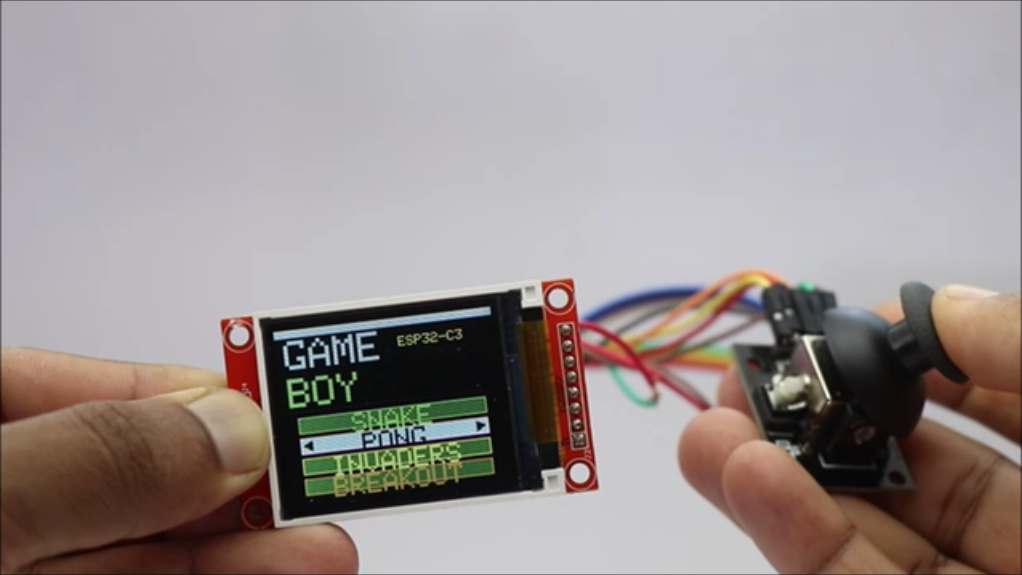
This is a small retro game boy loaded with simple games like the invaders, snake, pong and breakout these are not only the games you could play but even more can be added.
It is fully programmable, and there is no fixed number of games, any retro games you could think of can be played on this device.
Powered by an ESP32 C3 Super Mini controller and an LCD display you can expect decent graphics and the most important thing is it is powered by USB.
Connect to any USB power source and then you can play as much as you want without any limits.
Tried to make as small as possible and considering all the electronics standard size this was the least i could go, If you have a smaller competitor bring it out! let me see.
Supplies
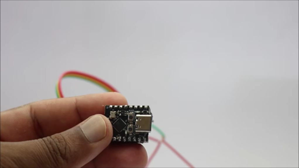
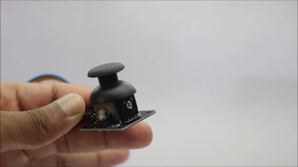
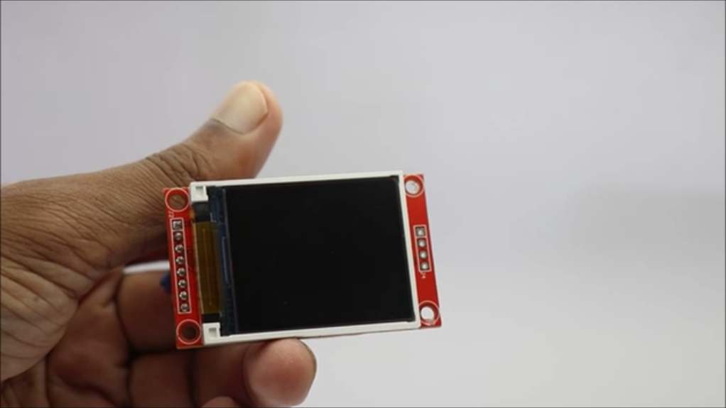
These are the materials that you will need to build this
Esp32 C3 Super Mini from amazon
Joystick Module
Jumper Cables
3D Printer
Tinkercad (optional if you want to edit my design)
Slicing Software(I used Cura slicer)
Hot Glue
Super Glue
Arduino IDE
Type C cable
Time to Play Game!
These are the affiliate links and upon qualifying sales i will receive a small percent of sales at no extra cost to you
Console Design
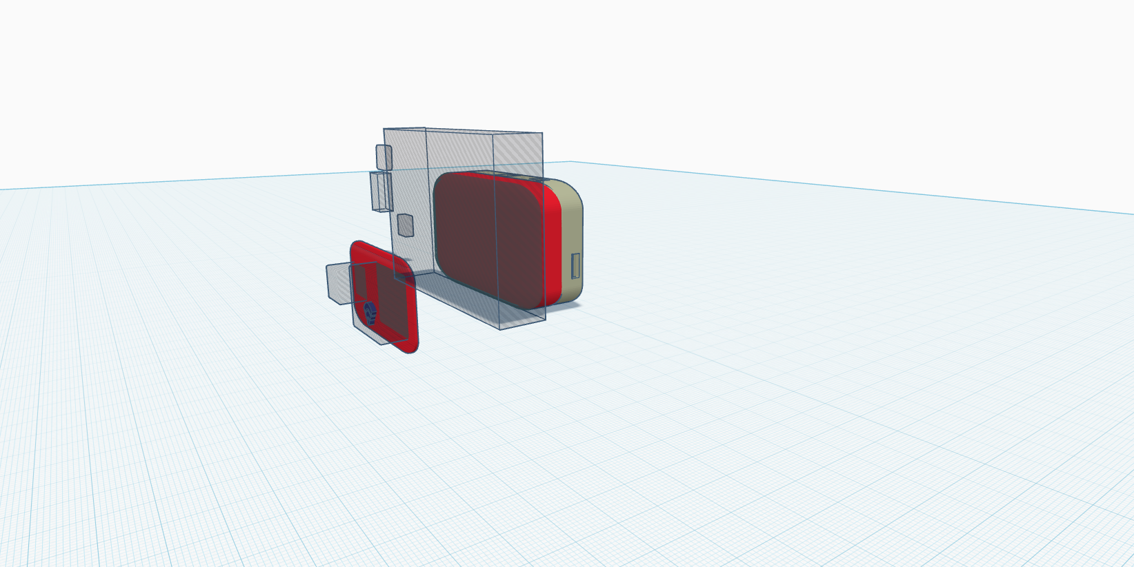
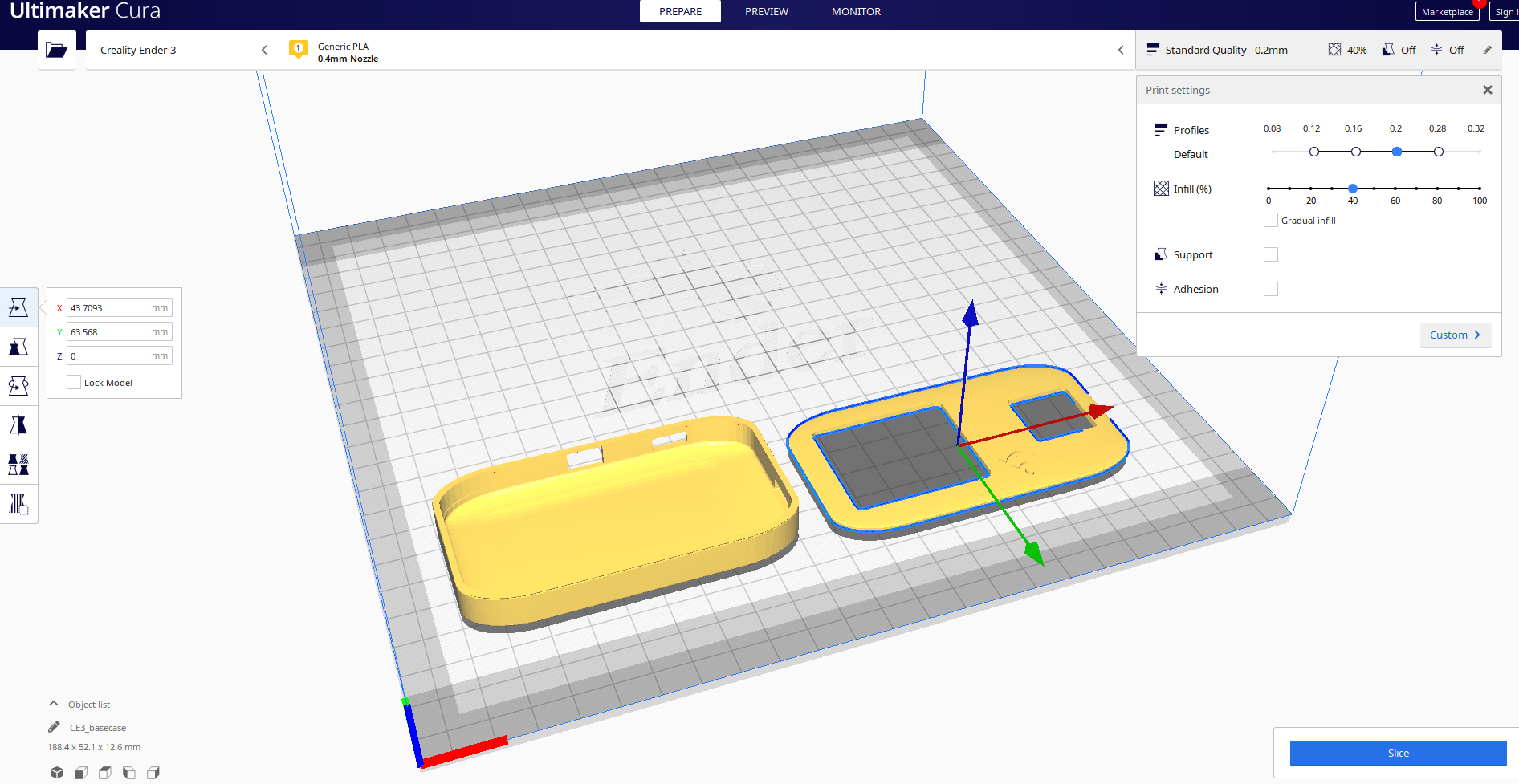
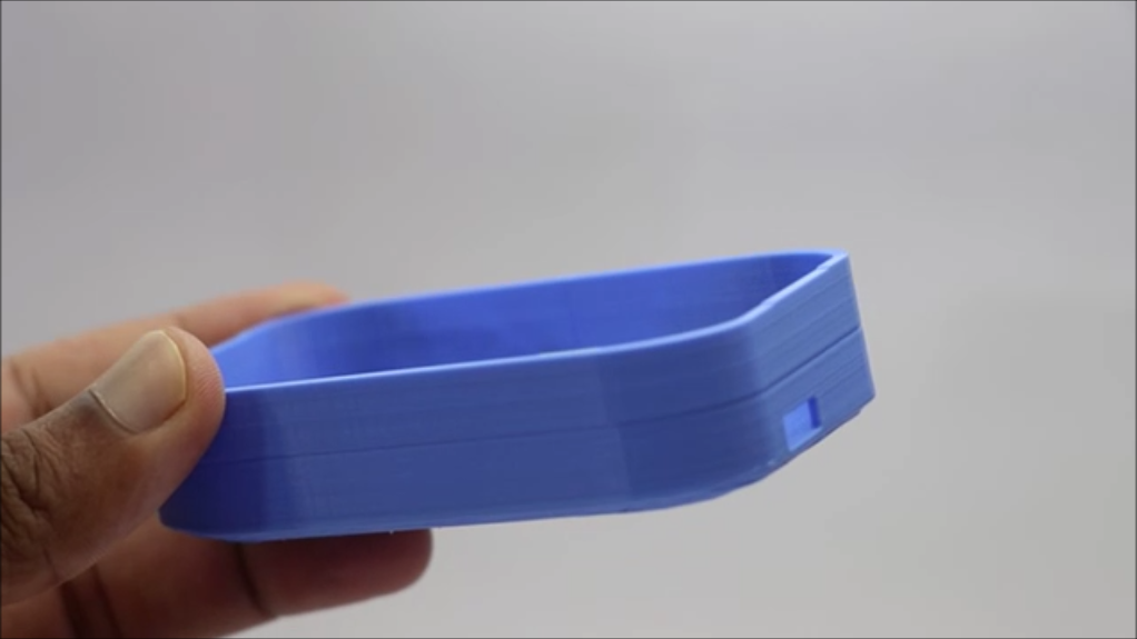
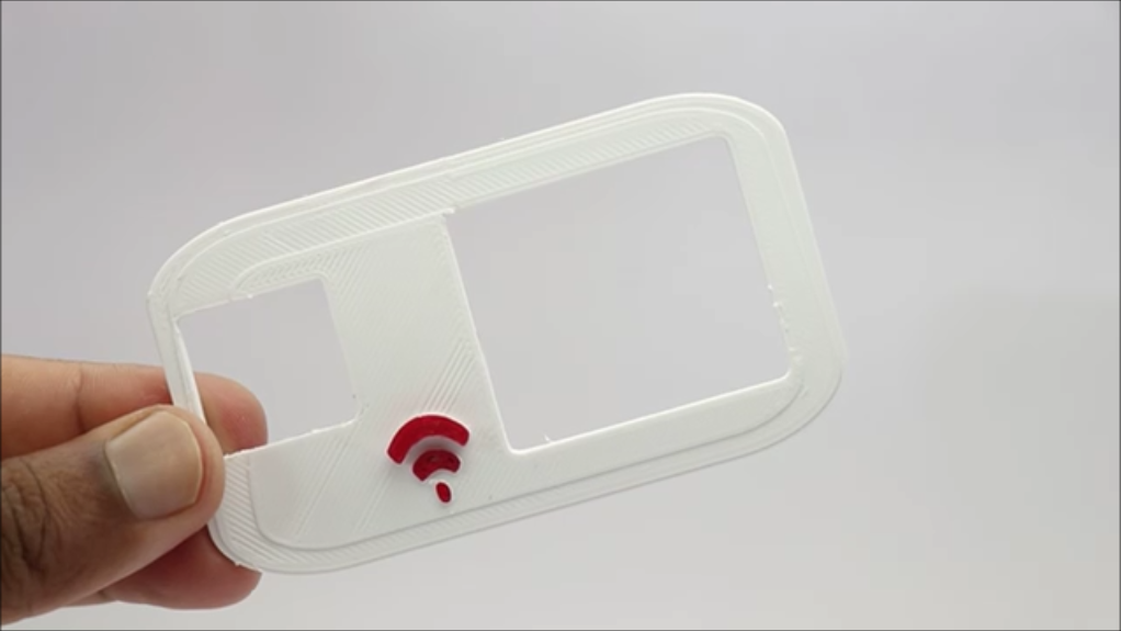
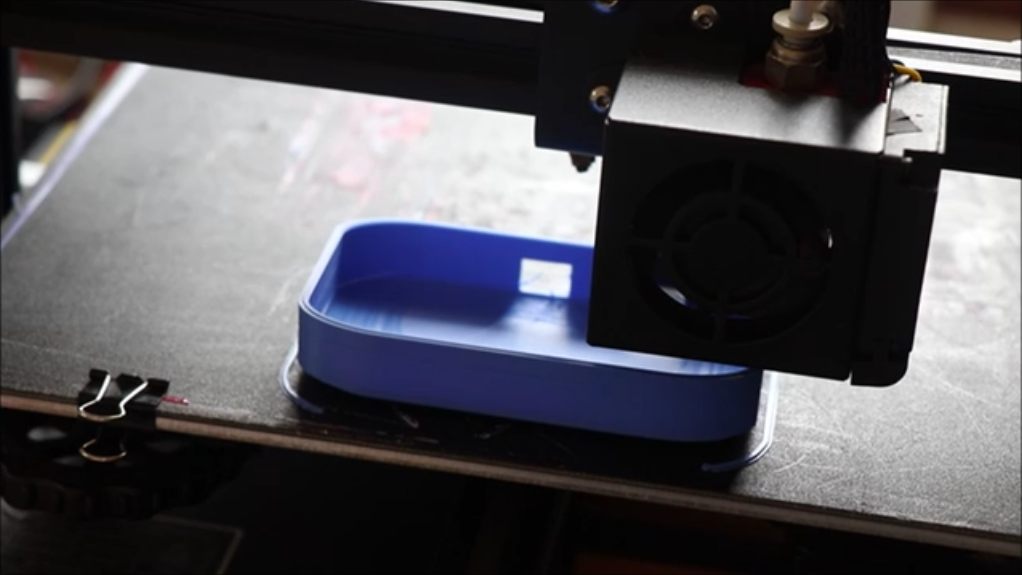
I used Tinkercad to design the frame or the console, I would say to be more specific.
There was no much of a complicated design my main aim was to make the game console handheld and for this i had to make sure the frame takes up all the components inside without consuming unwanted space.
I came up with this rectangular type of design since the largest component on this project was the lcd and taking this into consideration, I made this design.
The total number of parts for this project is only 2 and I have given a link to those STL files in this step.
You can either print both parts at once or could print one after the other.
I wanted to 3d print these parts in different colors, so I chose to print the base part with blue and the top part with white.
This is totally dependent on a person's interest of colors, the time for 3d printing was around 1:30 mins for me and it may differ for you according to the type of printing speed.
PLA filament works best here and most of us will be using the same.
Once all the parts are 3d printed with your choice of customisations, we can head over to making the circuit.
Circuit and Code
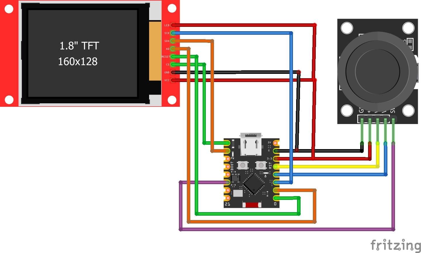
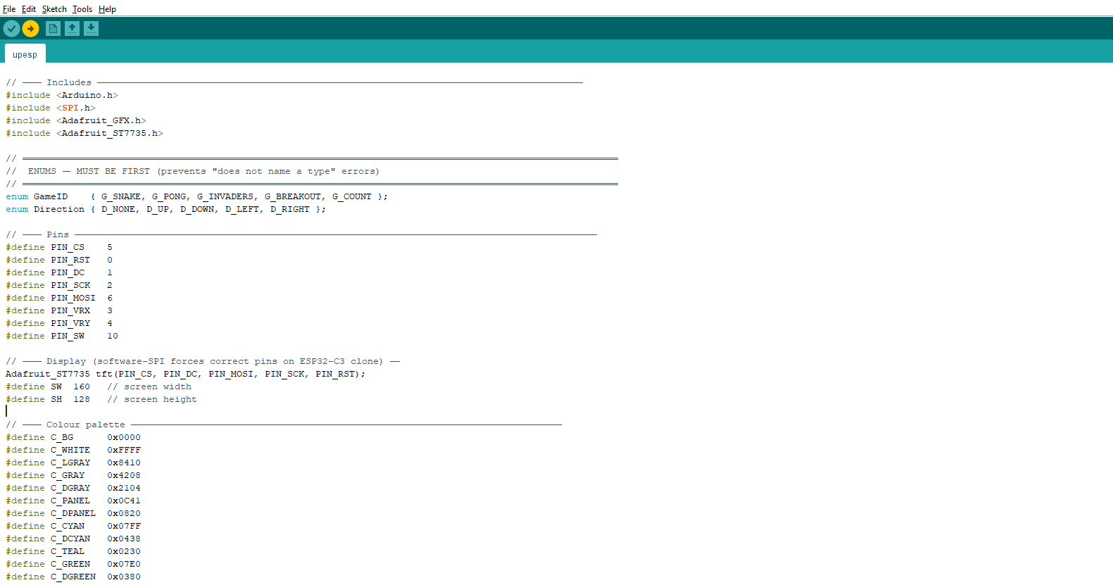

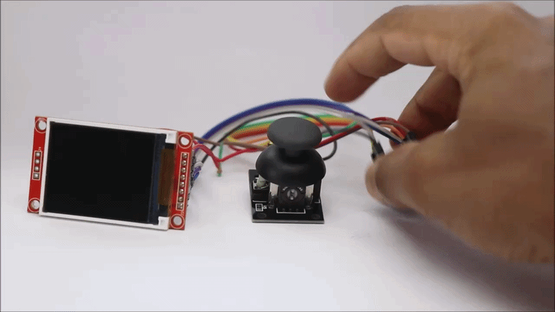
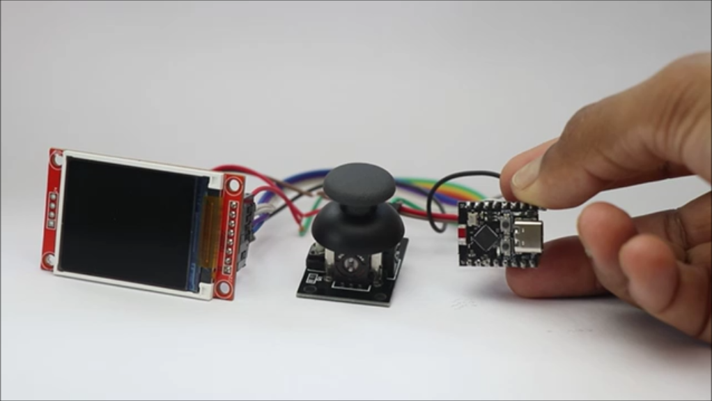
The circuit is not so complicated as you think in the first glance after watching this circuit diagram! The LCD have so many pins and every single of them is connected to esp32 board directly
There are total of 8 pins on the ST7735S TFT display and the connections are as follows
VCC to 3.3V
GND to GND and the LED pin to 3.3V on esp32
CS to GPIO5
RESET to GPIO0 and A0 to GPIO1
SDA to GPIO6 and the SCK to GPIO2
The joystick module has 5 pins and the connections are as follows
VCC and GND to 3.3V and GND
VRX to GPIO3 , VRY to GPIO4 and the SW to GPIO10
These are the connections and you can make some adjustments to the jumper cables so that both the components can share common ground and power.
Want a professional grade circuit for this project?
Get a custom high quality PCB from JLCPCB they have all the PCB services for any type of projects.
For PCB design use their EasyEDA tool which comes with many advanced options.
Im very happy with their services and they offer fast shipping, First time? Visit them to avail great coupons and offers.
Connect the esp32 board to usb cable and connect to computer and open arduino ide
Use the below program and select the type of board as esp32 c3 dev board and proper port and then click on upload.
After the program is done uploading the screen shows the game panel and you can check for its working by navigating the controller buttons.
Downloads
Casing the Components
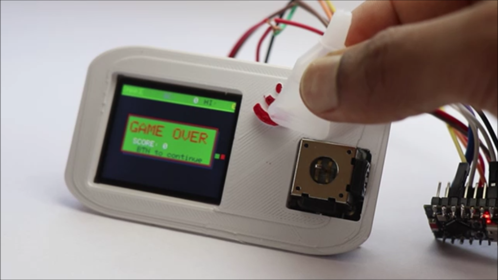
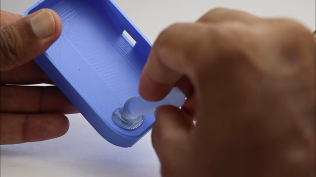
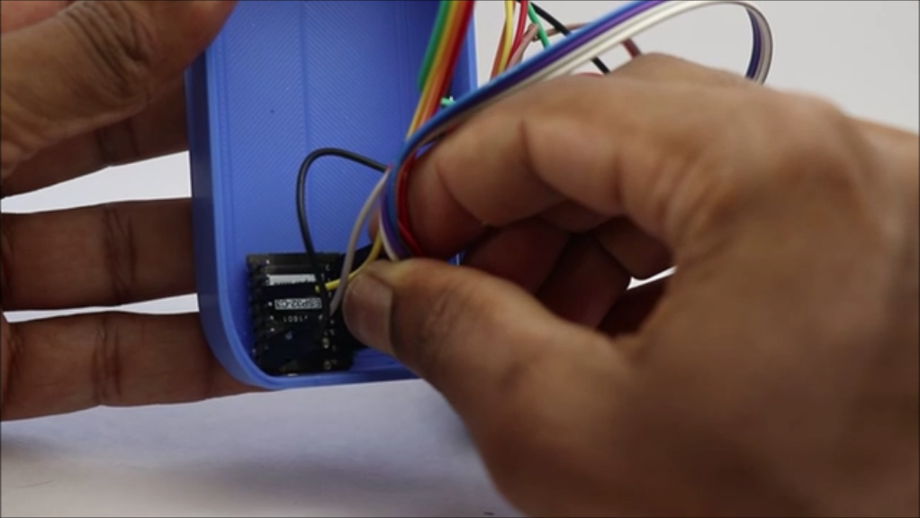
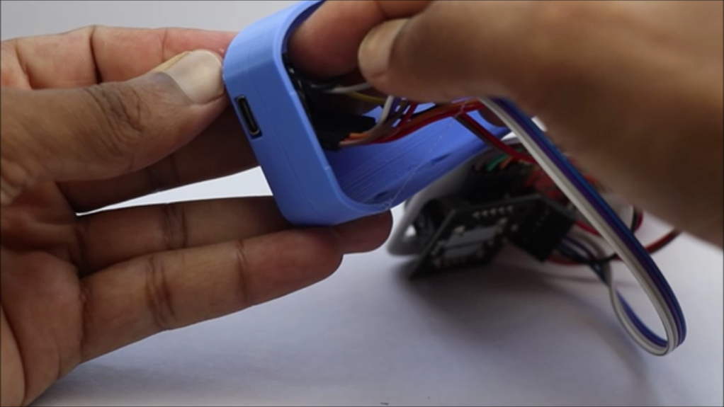
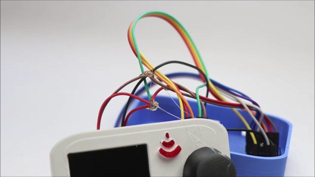
Start by gluing the screen to the 3d printed lid and then repeat the same for the joystick module also, I chose to use hot glue and you can do the same too.
I used tiny drops of superglue to hold the joystick module in place and this makes the process look neat without any residue.
Now after the workings are complete on the lid part we can head over to the base part.
I will use hot glue stick melted and pasted directly on the 3d printed enclosure base and to here i will be adding the esp32 board.
Press and hold firmly until the glue is dry completely, Now you can organise the jumper cables.
If you have any open ends, seal it with hot glue so that there is no chance of circuit issues.
Now connect the esp32 c3 board with power supply from a USB cable to make sure there is no disconnect between the wires when you were busy attaching the components to the base and the lid 3d printed parts.
Once you have verified all the circuits, we can assemble these 2 parts and finish the build part and let see how that is done in detail in the next step.
Finishing and Using
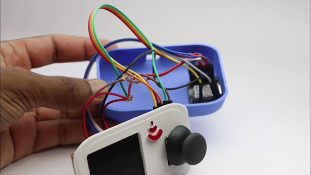
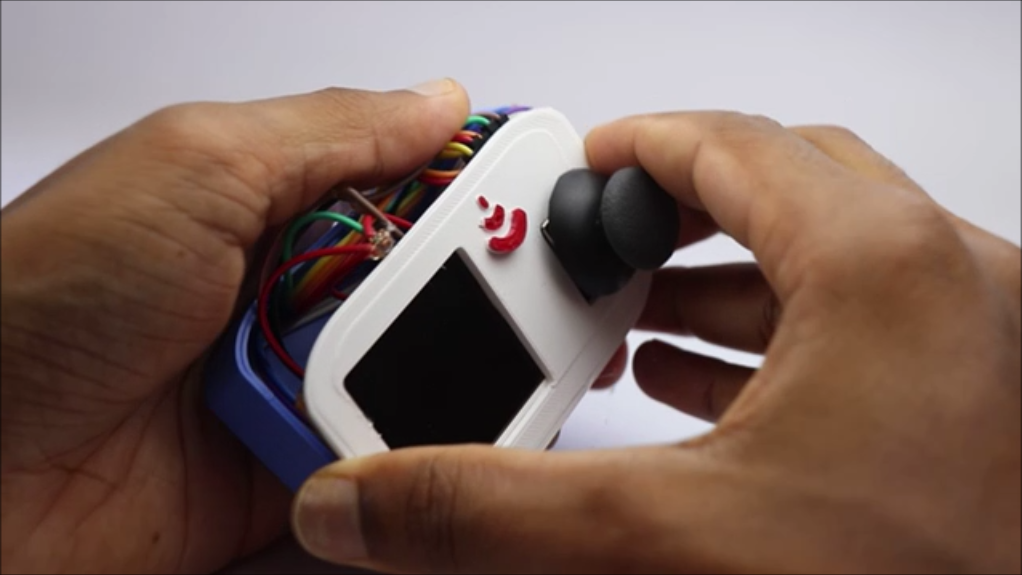
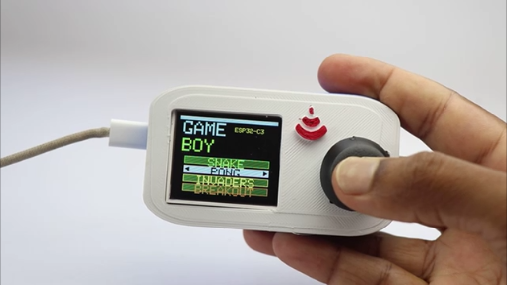
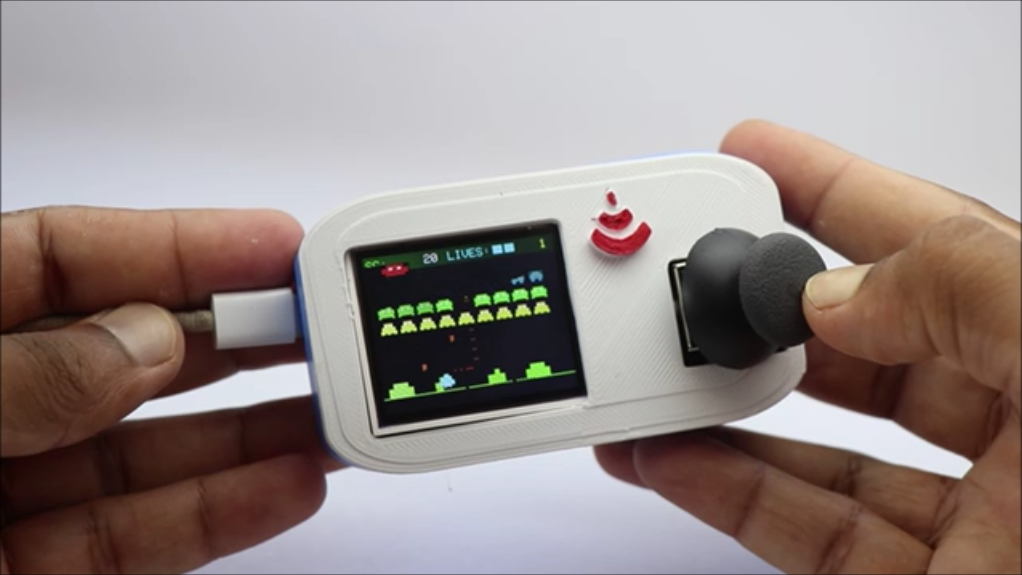
Finishing is nothing but i would call the fusion of the 2 3d printed parts that hold all the electronics inside them.
There are 2 parts here and i will use a tiny drop of super glue to couple these and we now have a game console that we built at home ready to be tested.
Simply connect this console to usb power supply here the pin type is c and you can power from any power sources like a power bank and laptop also.
When you connect this to any power source the display turns on and now you have options to navigate between the games and this is done using the joystick module buttons.
If you press ok the selected game will open and you can start playing like the normal console and there is a score running and if the game is over the menu wil be navigated automatically.
You can select a new game after you come back to main menu and start playing.
You can add other new games too, If you wish you just need to make some changes in the program and you are good to go.
We are now in the last step of this project and hope you will try to build this project, im hoping to see many versions of this project on the i made it section.
Thank you for making it till here and like always if you have any questions ask me in the comments and i will be happy to answer you all.
Working Video
)
Here is a detailed video that not only shows the building but also the playing of games!
How fun this device is i feel personally since i can add my custom games and play wherever and whenever I want without the need to charge the batteries!
This was all about making this handheld retro gaming console! If you have any suggestions for this console im happy to consider.
Thanks and hoping to see many variants of the build from this community! Thank you and happy gaming.