DIY Ice-Powered Personal Air Cooler
by OrionNebula in Living > Life Hacks
327 Views, 2 Favorites, 0 Comments
DIY Ice-Powered Personal Air Cooler
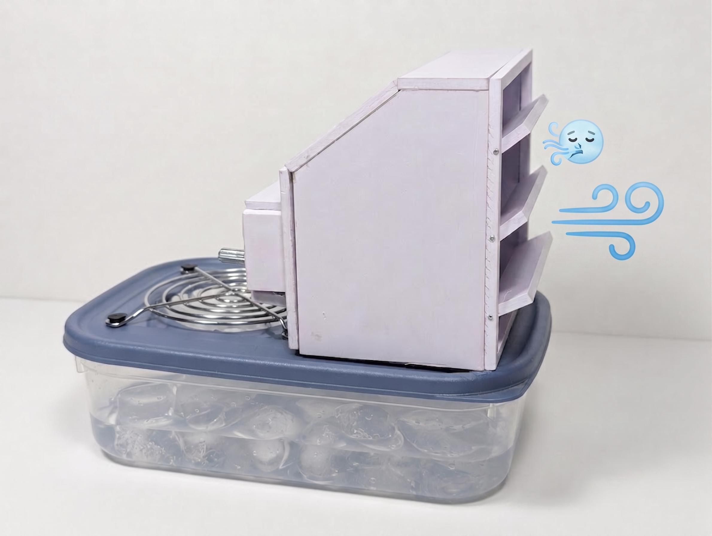
When the temperature gets uncomfortable, one of the simplest ways to cool down is to get some cold air moving. A regular fan can make you feel cooler by increasing the evaporation of sweat from your skin, but it does not actually lower the temperature of the air. I wanted to take that idea a step further by combining a fan with something that can actually absorb heat: ice. The result is this DIY personal air cooler, which uses a fan to draw air through a chamber containing ice and then directs the cooled air toward the user.
The basic idea is quite simple. As warm air passes over the ice, heat is transferred from the air to the ice, causing the ice to gradually melt. The fan keeps this air moving continuously, while the enclosed design helps direct the cooled airflow toward a specific area rather than simply releasing it in every direction. This makes it particularly useful for personal cooling at a desk, beside a bed, or anywhere else where you need relief from the heat without necessarily having to cool an entire room.
This project is my take on the Beat the Heat challenge: instead of trying to overpower the heat with a large and energy-intensive cooling system, I have built something small, simple and focused on keeping a person comfortable. It combines airflow and thermal energy storage into a more interesting personal cooling device.
Supplies
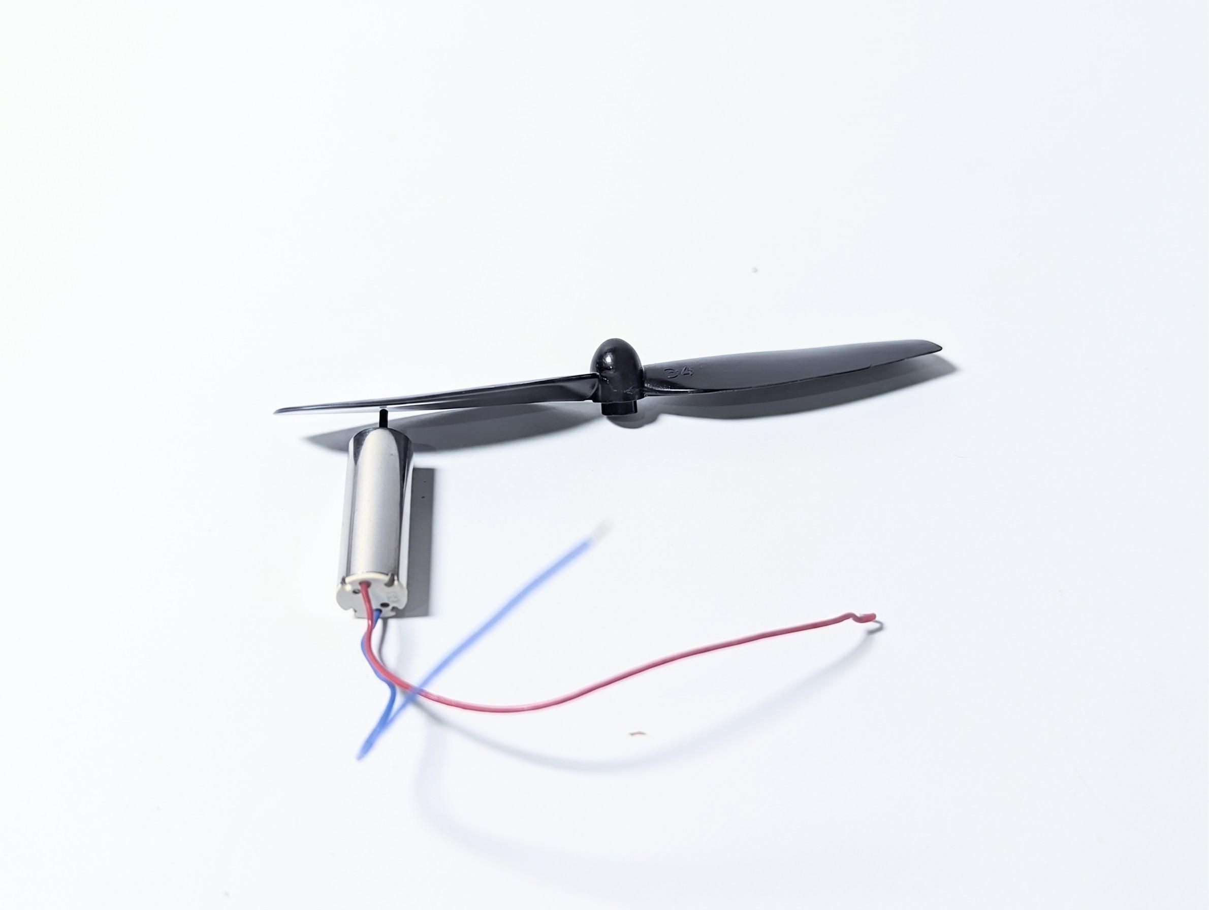
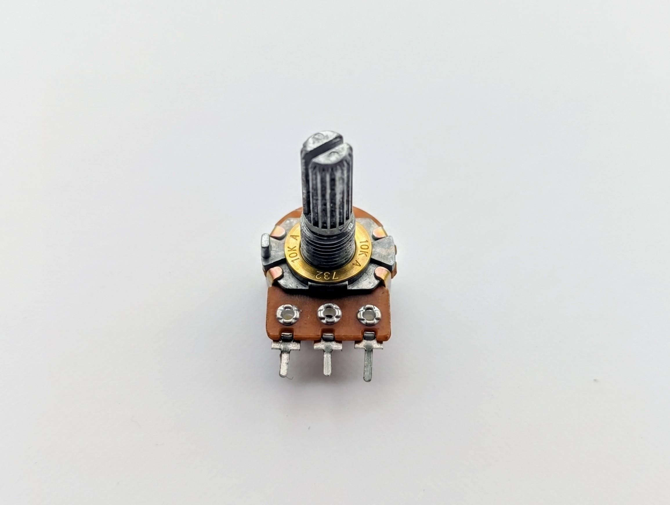
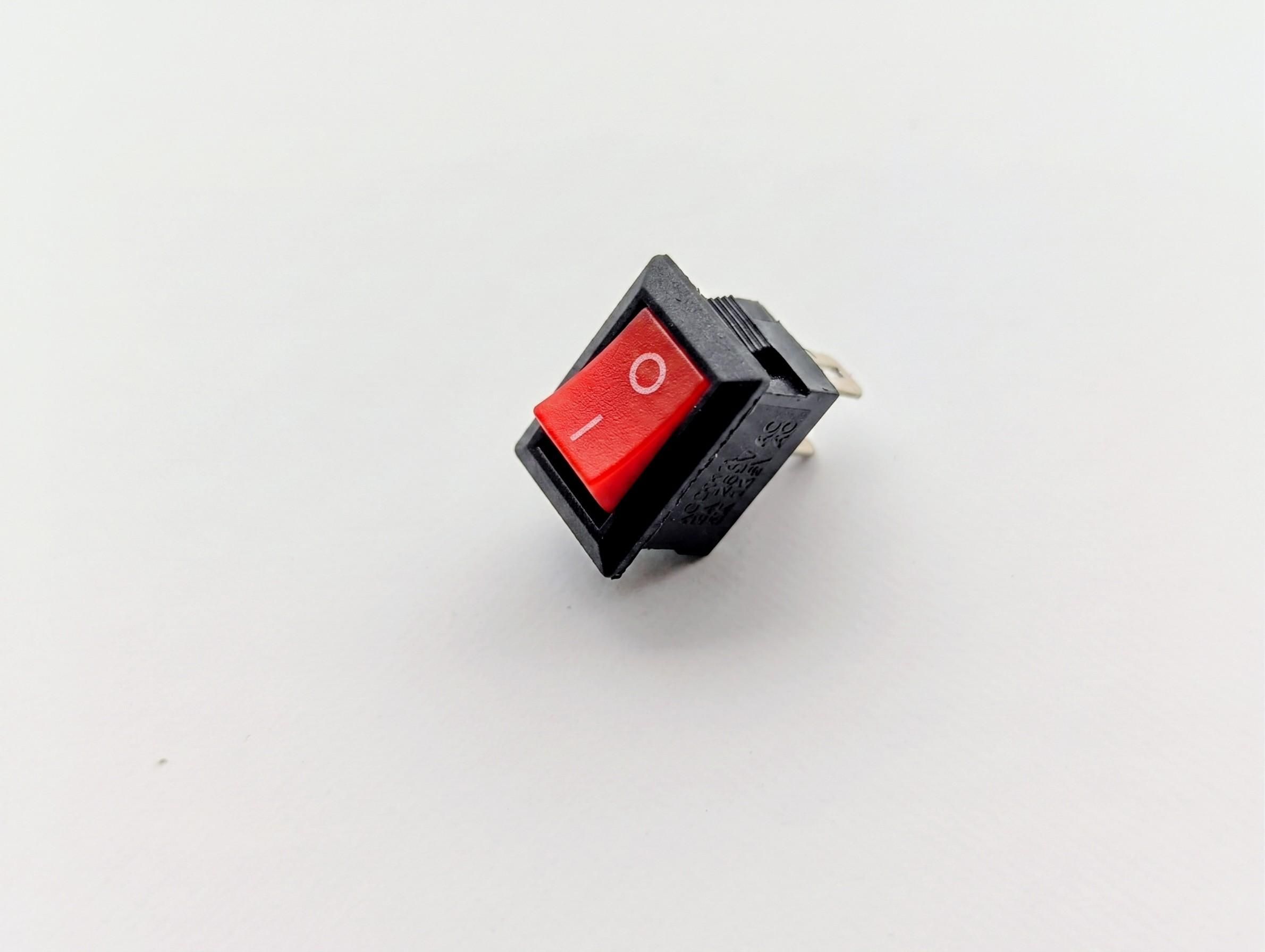
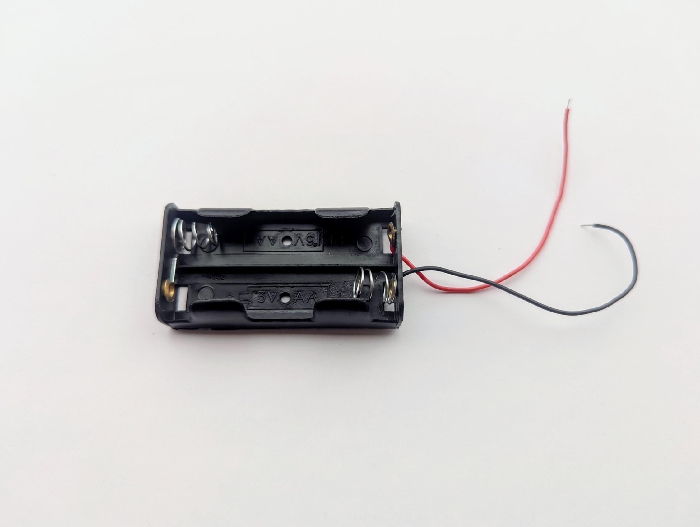
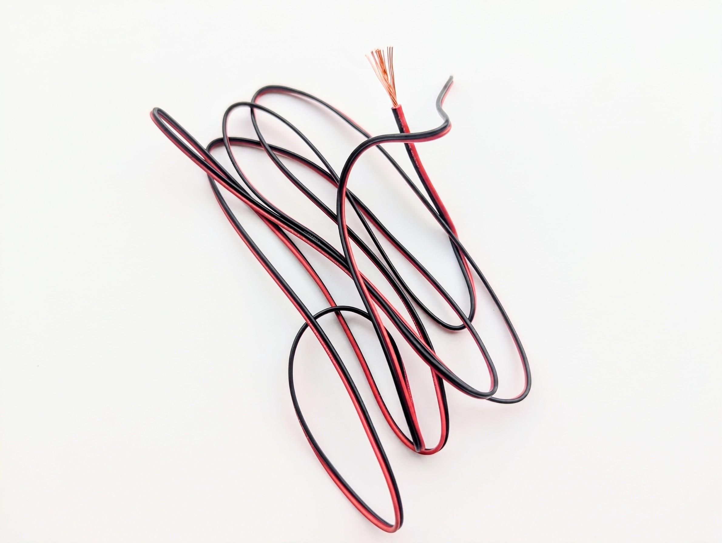
- DC motor
- Propeller
- AA Battery holder
- AA Battery
- Switch
- Potentiometer
- Connecting wires
- PVC foam board
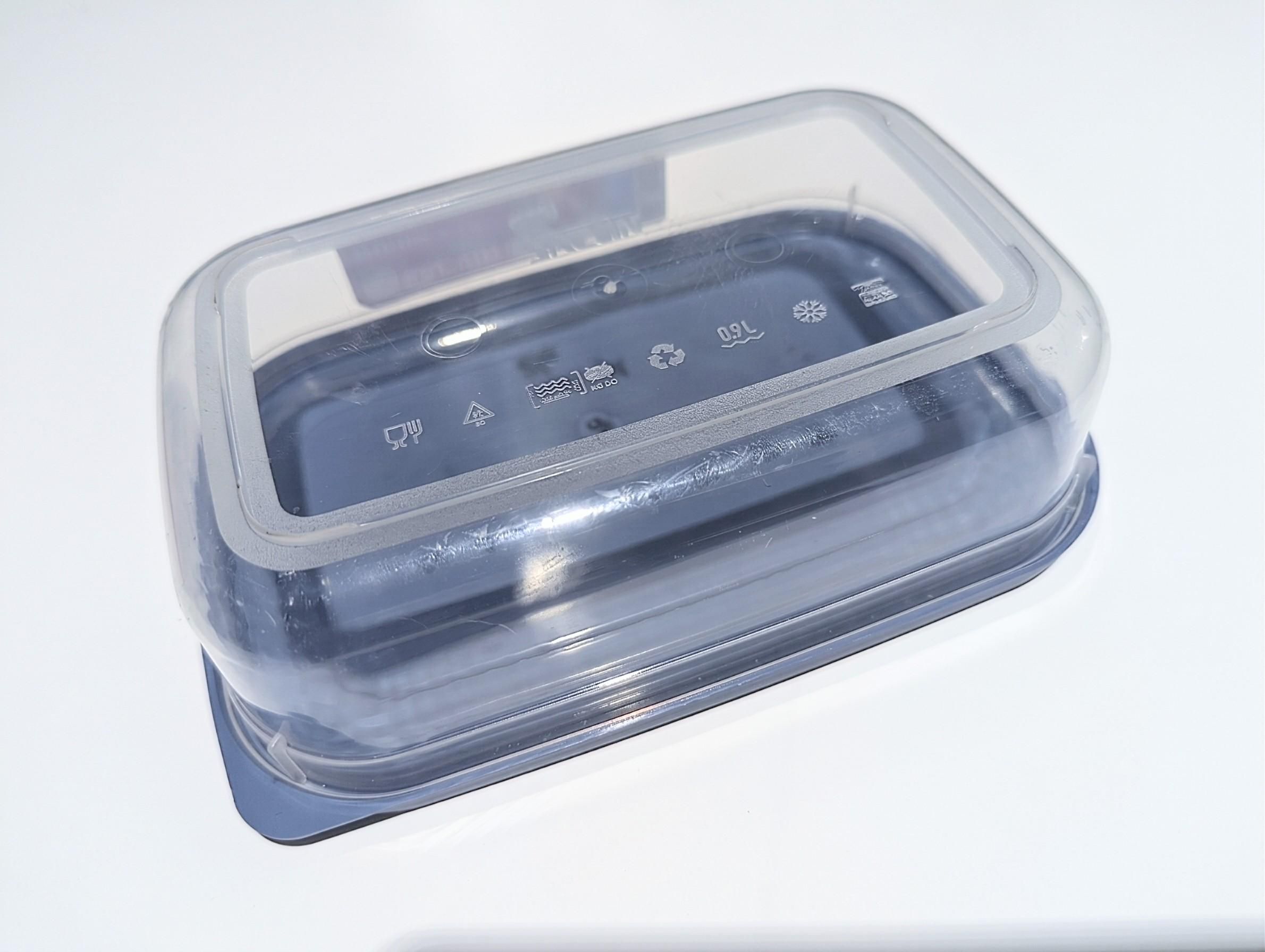
- Plastic container with lid
- Box cutter
- Metre rule
- Craft Glue
- Hot glue
- Heat shrink tubings
- Soldering iron and lead
- Fan grill
- Office pins
Building the Fan Motor Mount
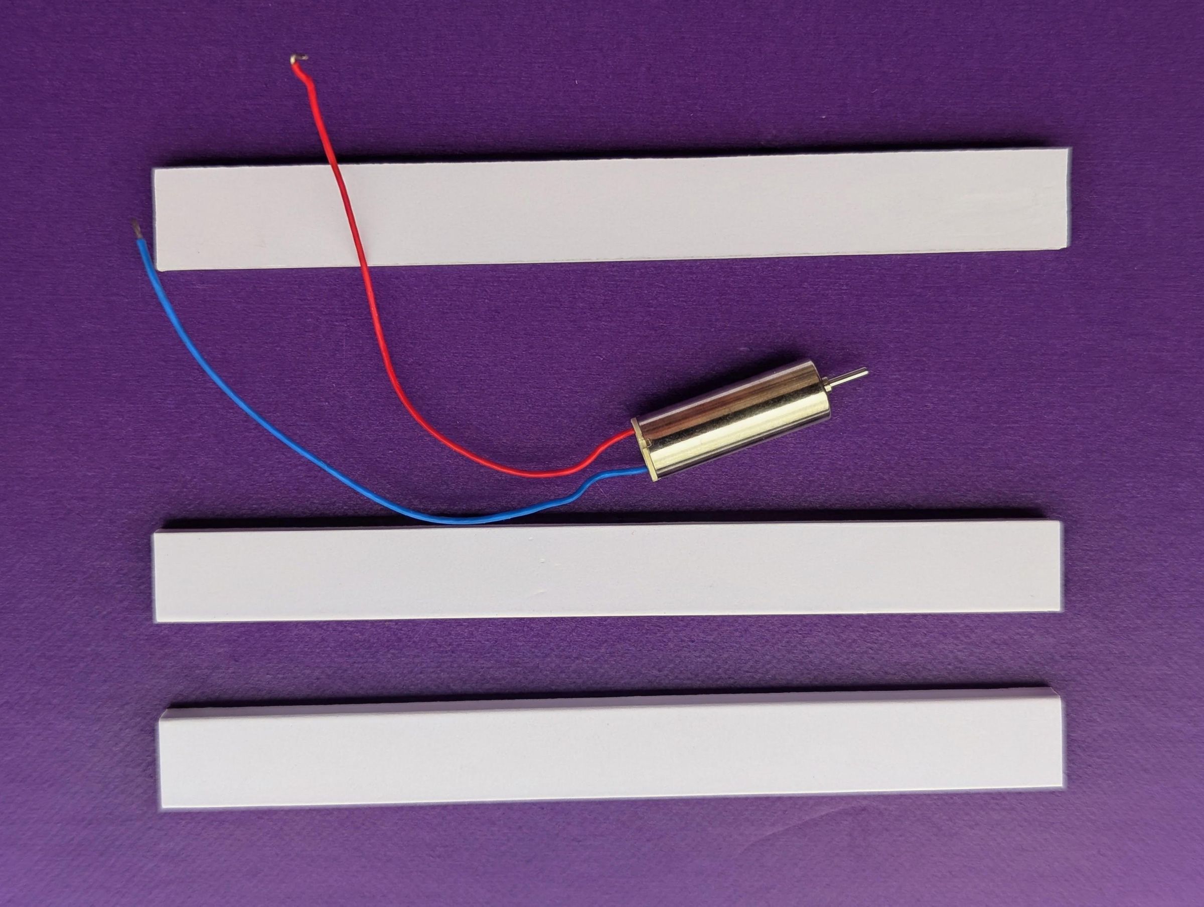
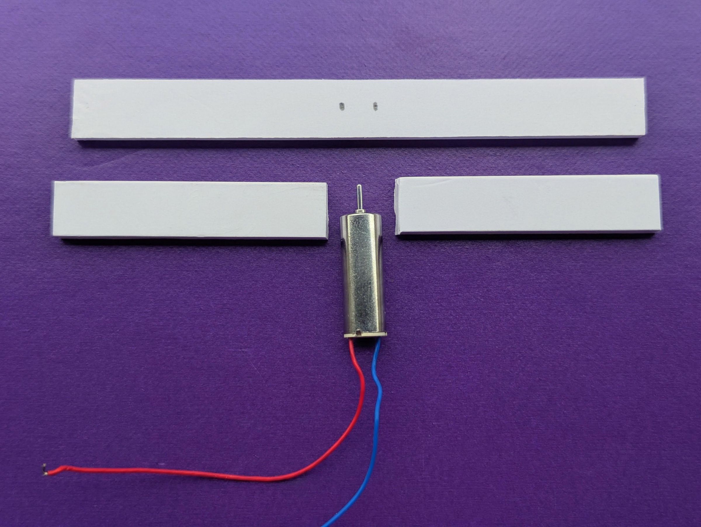
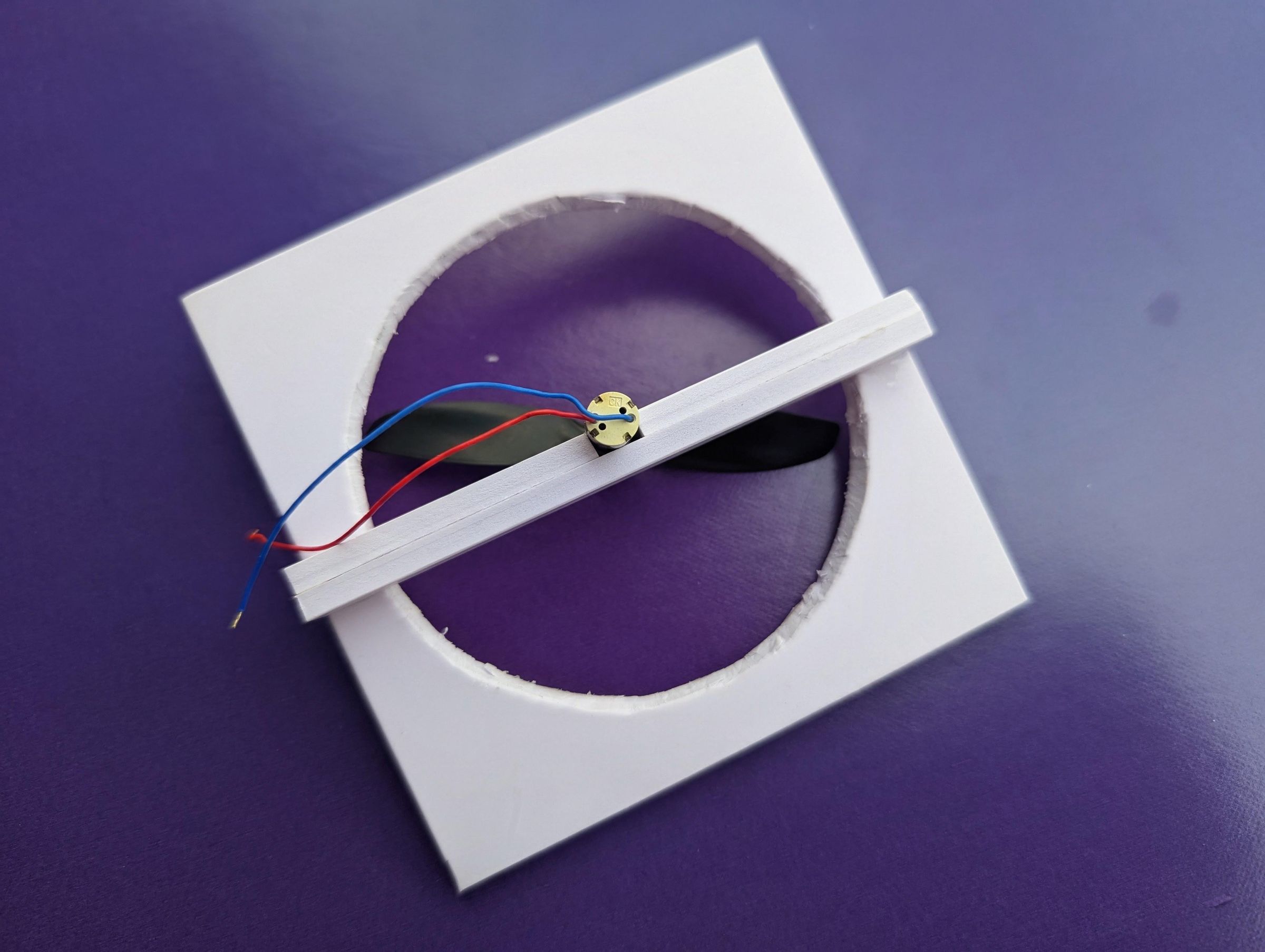
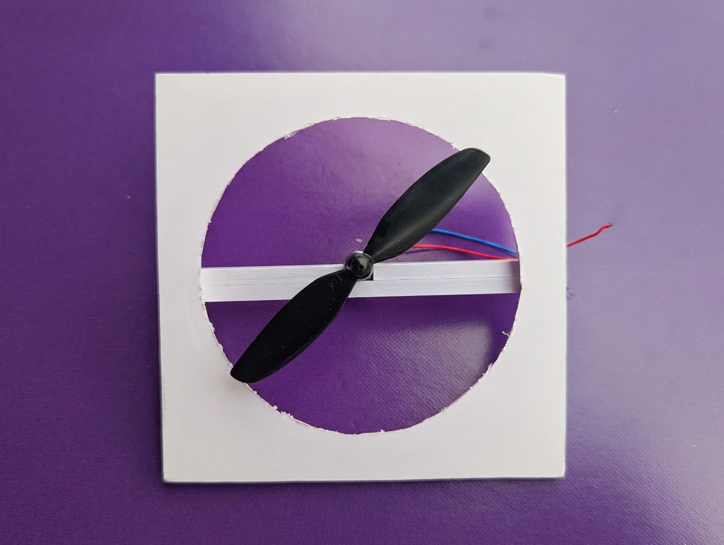
The first part I built was the frame that would hold the motor at the centre of the fan. For the motor, I used a small drum-style micro DC motor. These little motors are capable of spinning at a very high speed, and in my testing, it produced a noticeably stronger airflow than the small brushless DC motors commonly found in inexpensive toys. Since the whole purpose of this project is to move as much air as possible through the cooling section, having a fast-spinning motor was important.
To make the motor mount, I cut a square piece of PVC foam board and marked a circle at its centre. I then cut out the circular opening, leaving the square section around it as the main frame. Across the centre of this opening, I made a small support from thin strips of PVC foam board, layering and gluing them together to give the support enough thickness and rigidity. The DC motor was then sandwiched at the centre of this support and secured with glue.
The arrangement keeps the motor properly centred within the circular opening while leaving enough clearance around it for the fan blades to rotate freely. Getting the motor centred was particularly important because even a small amount of misalignment can cause the fan to wobble, make unnecessary noise, or rub against the surrounding structure. Once everything was glued together, I checked that the motor could spin freely before moving on to the next part of the build.
Downloads
Building the Air Outlet Chamber
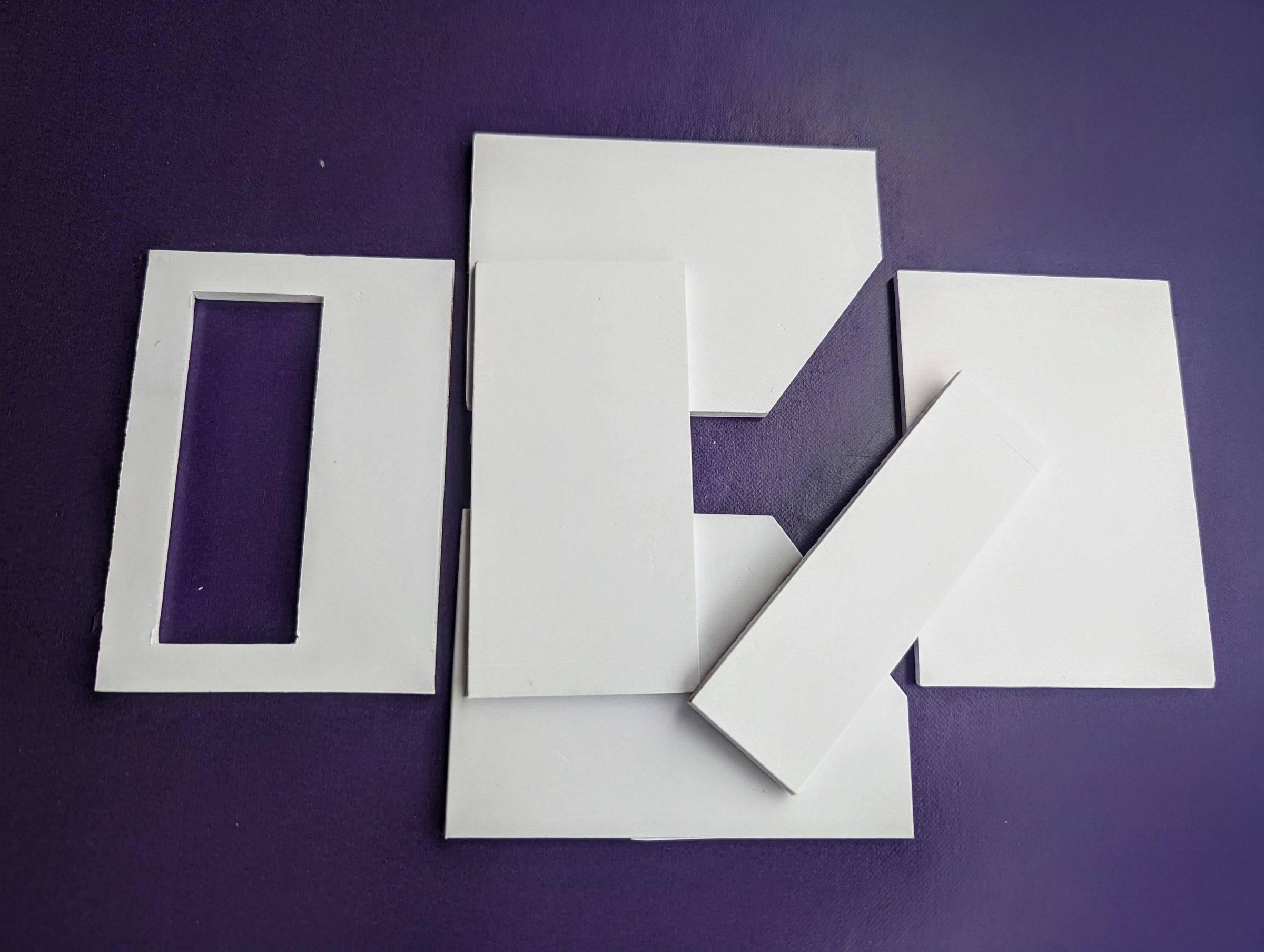
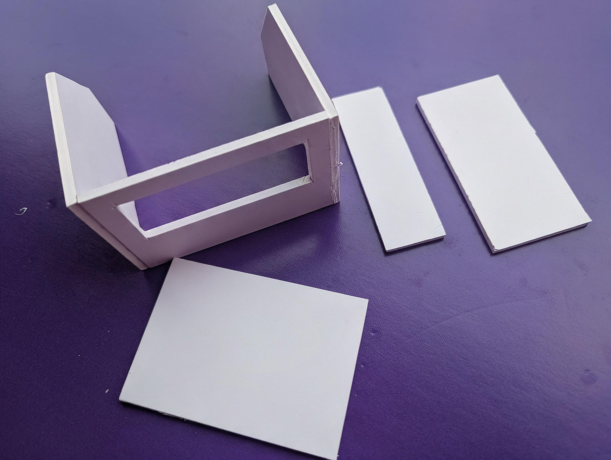
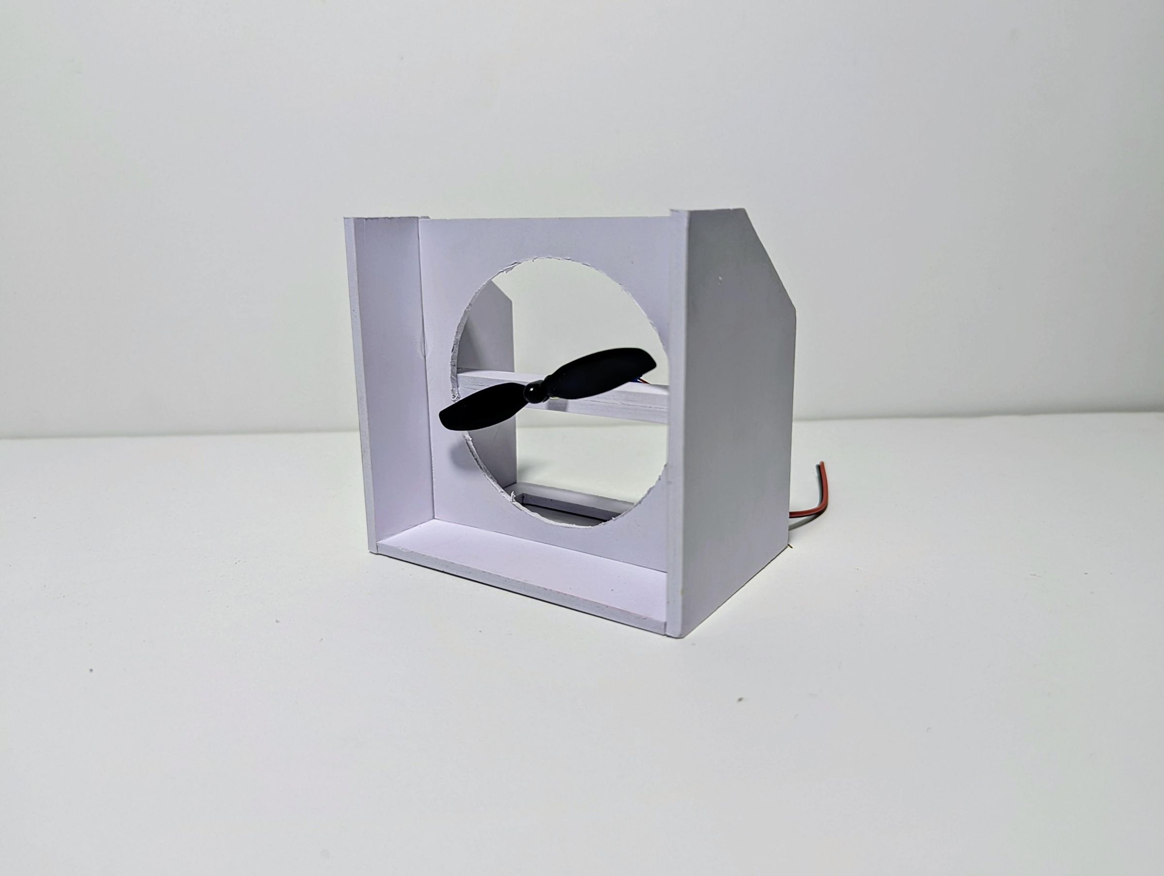
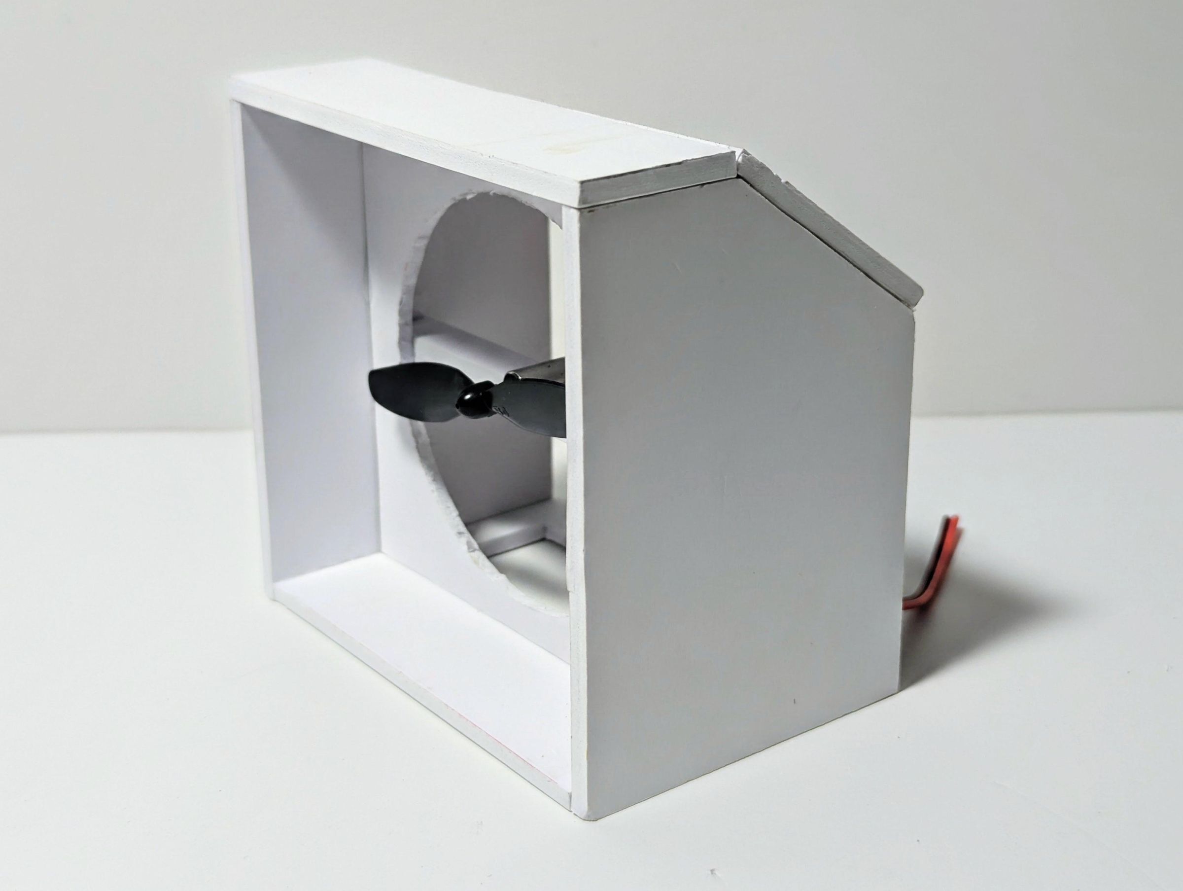
With the motor frame completed, I started building the chamber that would surround the fan and direct the airflow. I cut all the pieces from PVC foam board using templates, which I have attached to this step. Using templates made it easier to reproduce the shapes and dimensions accurately, especially since several of the pieces had to fit together around the motor frame. The first piece was the base, which is a rectangular panel with a rectangular opening cut into it. This opening will serve as the passage through which the cooled air from the ice chamber enters the fan section.
I then glued two side walls to the left and right sides of the base, forming the main body of the chamber. The motor frame from the previous step was positioned and glued between these walls so that the fan sits centrally within the chamber. After that, I added the top cover and the slanted rear section of the top. These pieces gradually give the chamber its final shape while also helping to guide the airflow toward the front of the cooler rather than allowing it to escape randomly.
At this stage, I deliberately left the back of the chamber open. This is where the electrical components and wiring will eventually be incorporated, so closing it up now would make the next stage much more difficult. Leaving the rear accessible also gives me enough room to install and test the electronics before the enclosure is finally completed.
Installing the Electronics
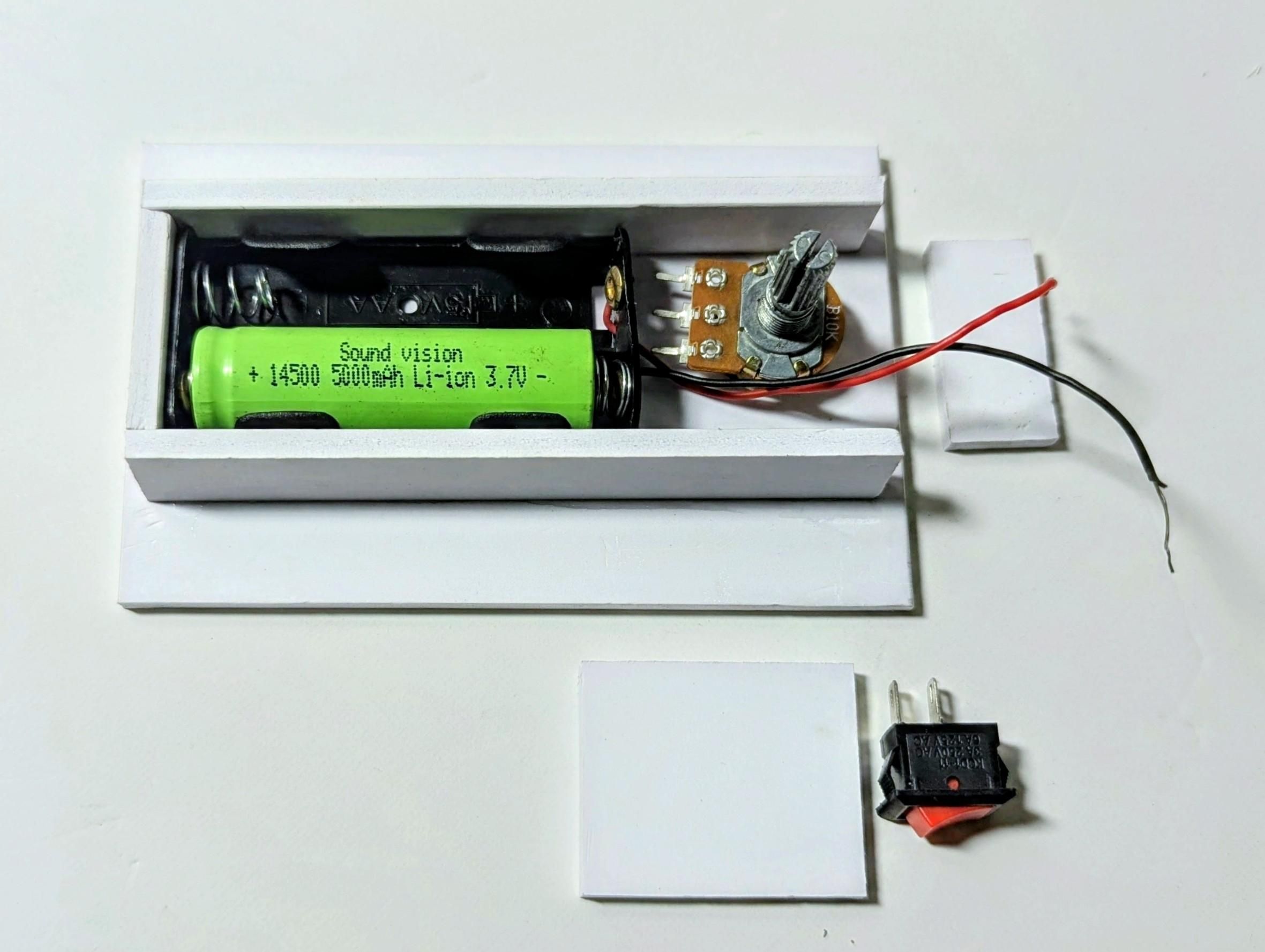
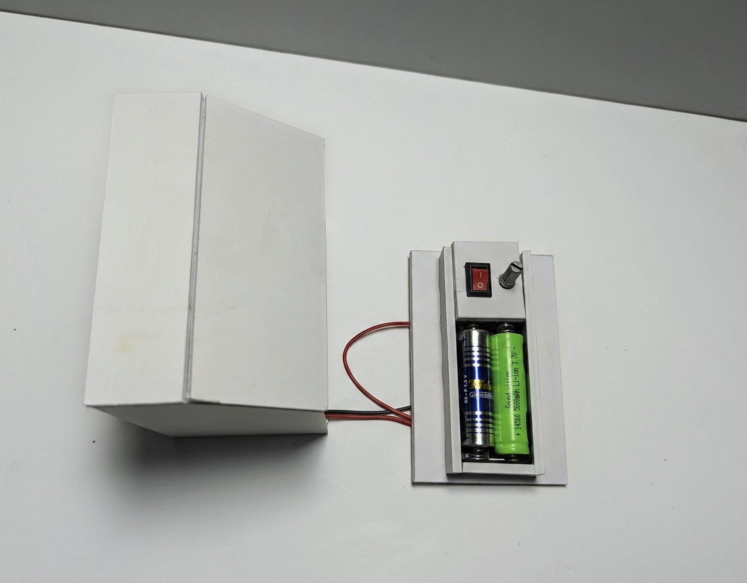
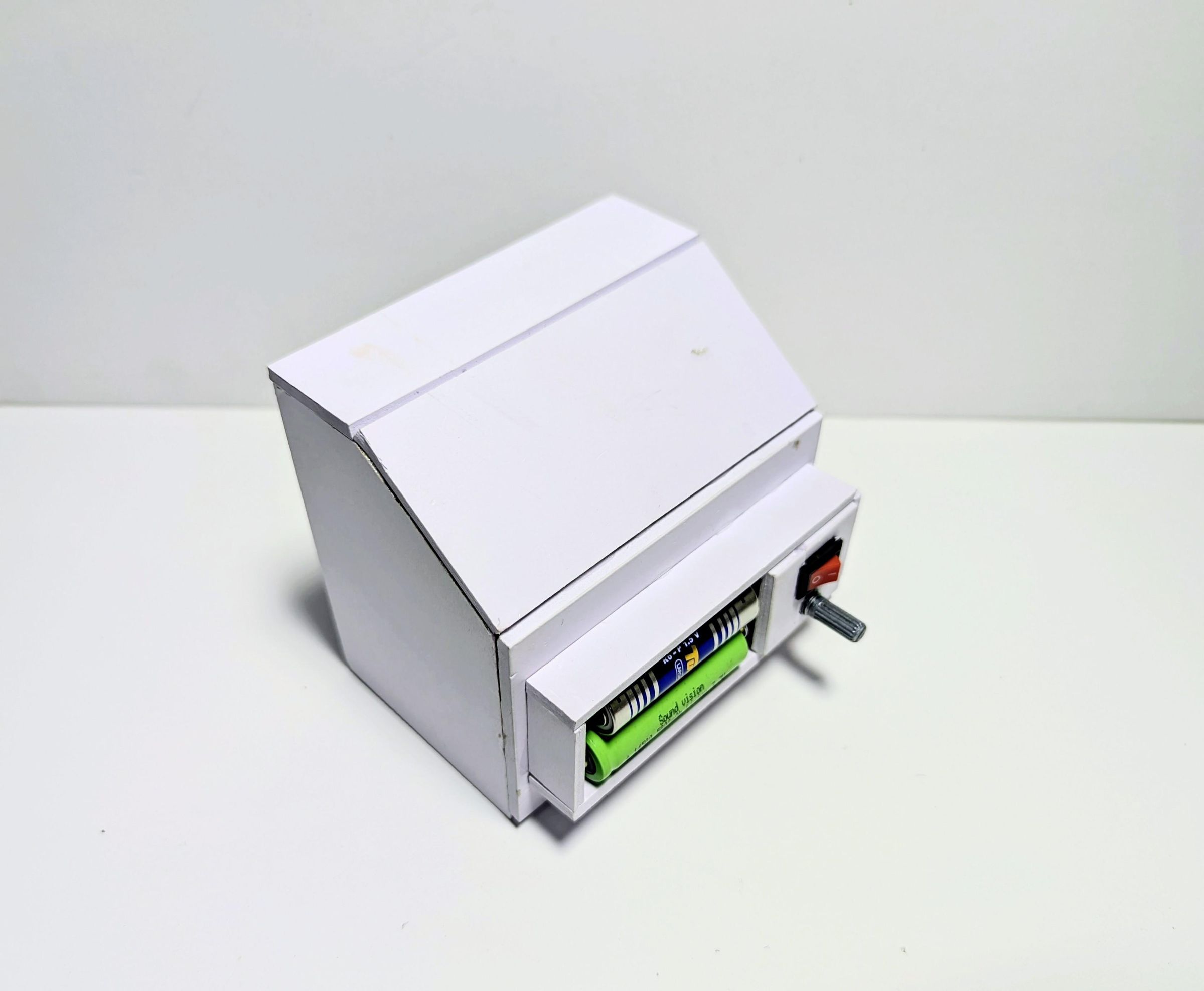
Before installing the electronics, I first took a small precaution to protect the motor from the humid environment that it would eventually be operating in. Since the fan will be drawing air through a chamber containing ice, there is a possibility of moisture reaching the motor terminals over time. I added a piece of heat-shrink tubing over the bottom terminal area of the DC motor to provide some insulation and protection against moisture. It is a simple addition, but I wanted to reduce the chances of corrosion or an electrical problem developing after repeated use.
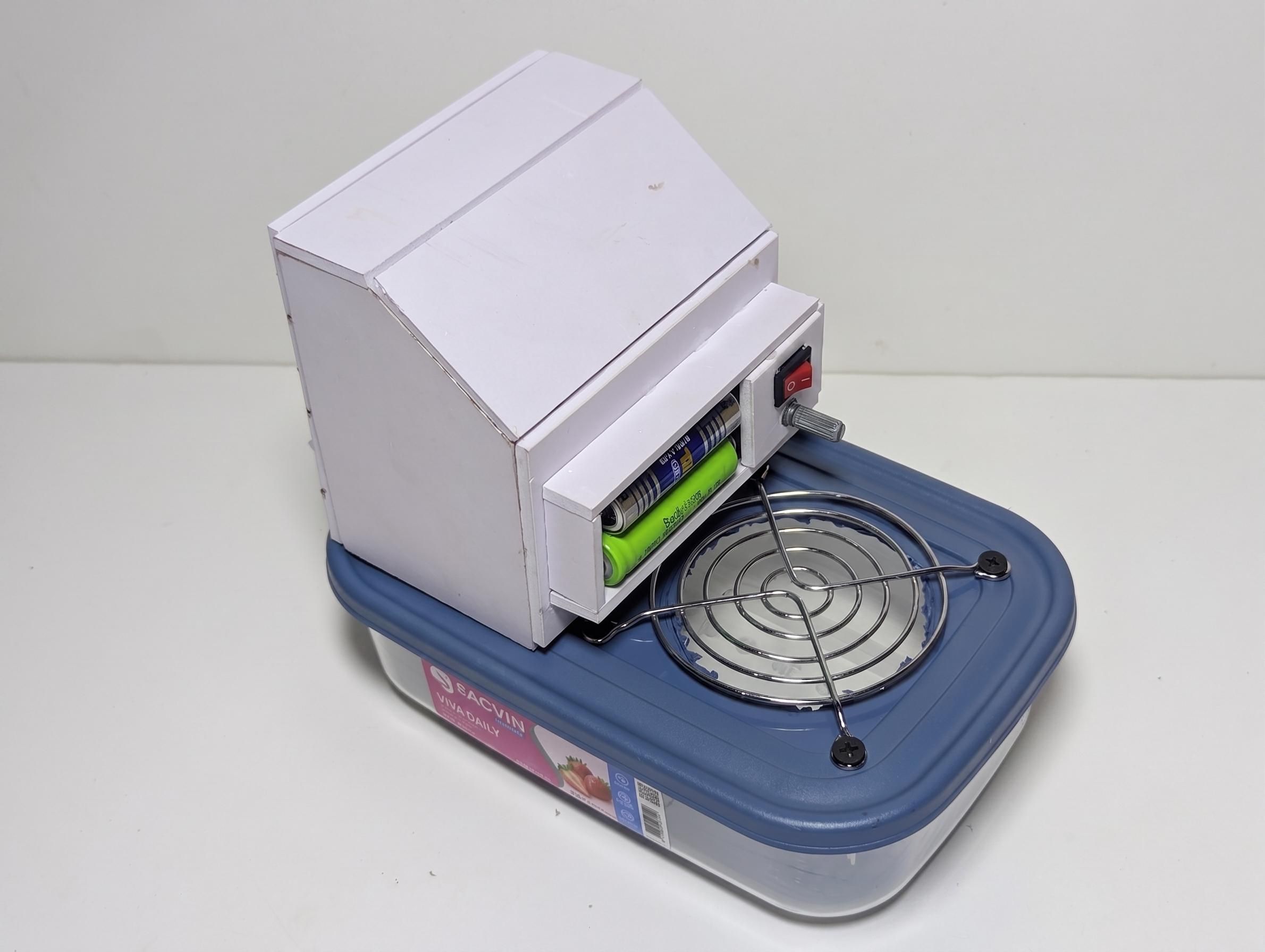
I then prepared the back cover of the air outlet chamber. Using the pieces from the template, I created a rectangular section that would accommodate the electrical components. The battery holder for two batteries was fitted into this section, along with a small potentiometer for adjusting the fan speed and a switch for turning the cooler on and off. The battery supply, switch, speed-control potentiometer and fan motor were connected in series so that the switch controls the whole circuit while the potentiometer allows the speed of the fan to be adjusted.
I soldered each of the electrical connections and insulated the exposed connections with heat-shrink tubing. Apart from helping to prevent accidental short circuits, this also gives the connections some protection from the moisture that may be present around the cooling chamber. Once everything was connected and tested, I folded the excess wires neatly and secured them against the back wall with hot glue. This kept the wiring from interfering with the other components and made the inside of the chamber considerably neater.
Finally, I fitted the remaining back panel over the electronics and glued it into place.
Downloads
Adding the Adjustable Airflow Director

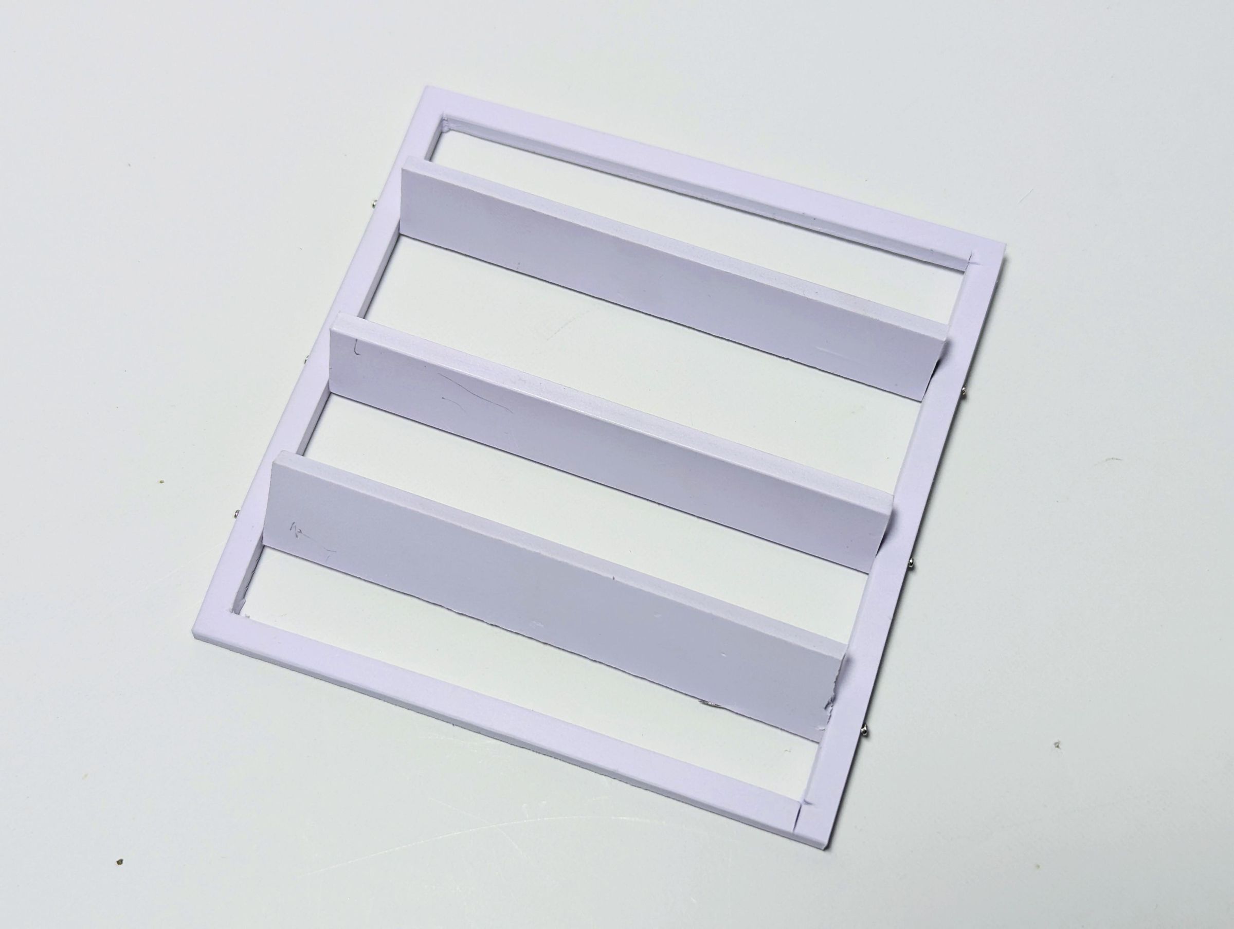
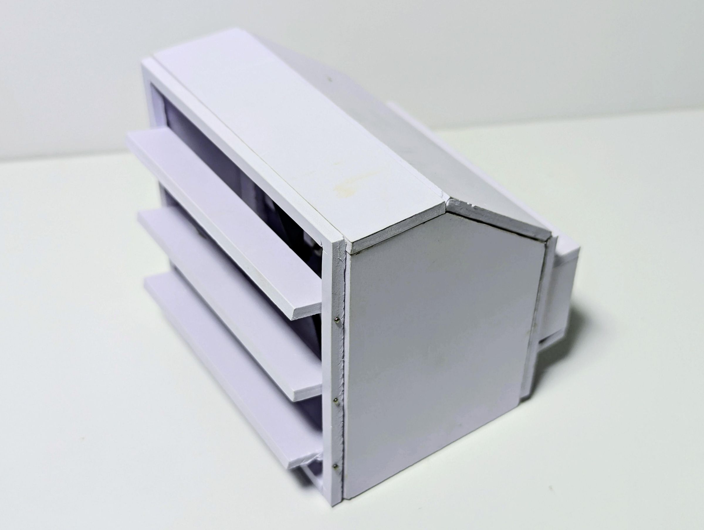
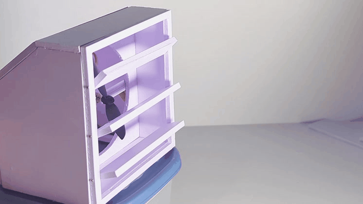
One limitation of this cooler is that, unlike a conventional desk fan, it does not have a neck that can be tilted upward or downward to direct the airflow toward the user's face. To solve this, I made an adjustable airflow director similar to the vents found in cars. The idea is simple: the direction of the outgoing air can be changed by tilting the individual vanes up or down, allowing the cooler to be positioned on a desk or other surface while still directing the cool airflow where it is needed.
I started by cutting a rectangular outer frame and three smaller panels using the templates attached to this step. Each panel was positioned at an equal distance from the next inside the frame. To allow them to move, I used two office pins for each panel, with one pin on either side. The pins were passed through the outer edge of the frame and into the corresponding panel. This holds each panel securely while still allowing it to rotate freely around the pins.
Once all three panels were installed and checked for smooth movement, I glued the completed frame to the mouth of the air outlet. The three vanes can now be tilted together to change the direction of the airflow. This small addition makes the cooler much more practical because the user does not have to physically tilt the entire device just to move the airflow higher or lower.
Preparing the Cooling Chamber Lid
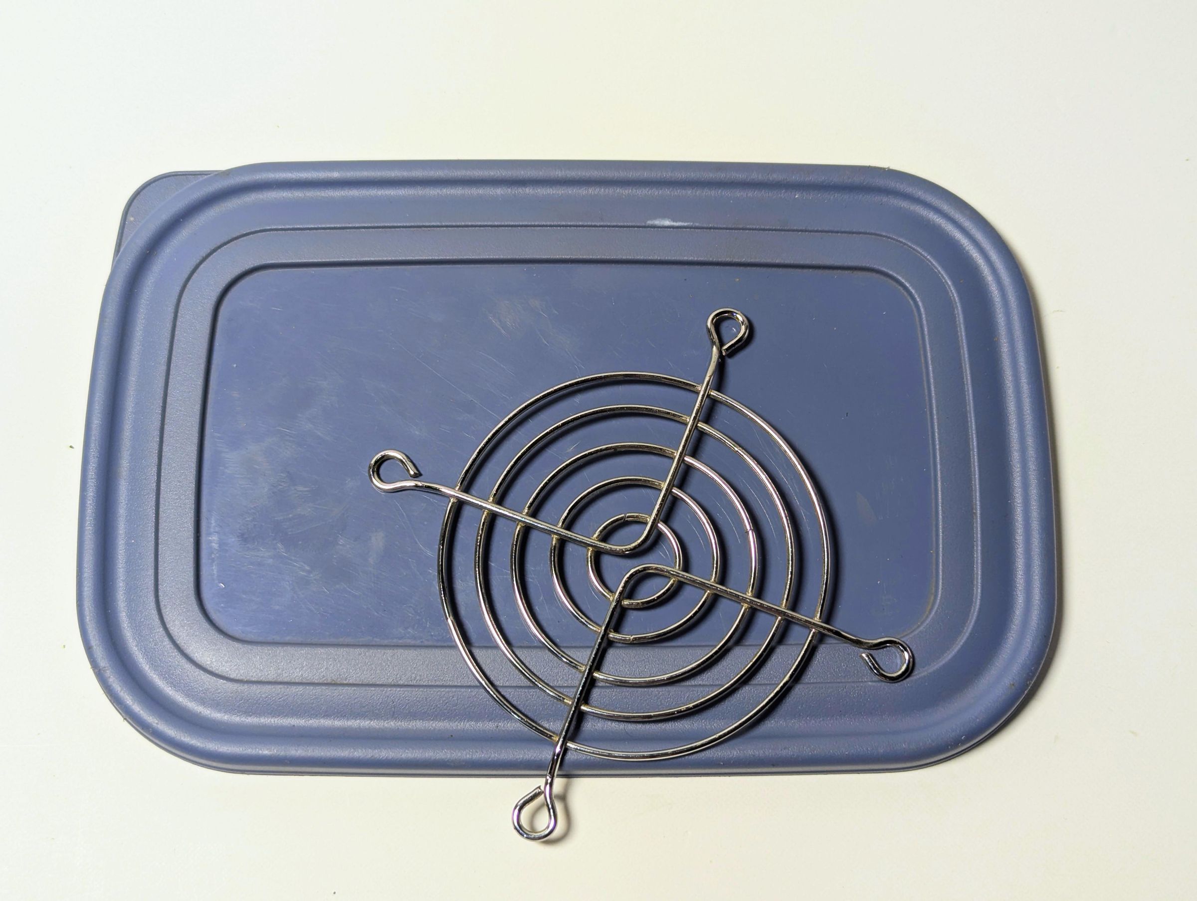
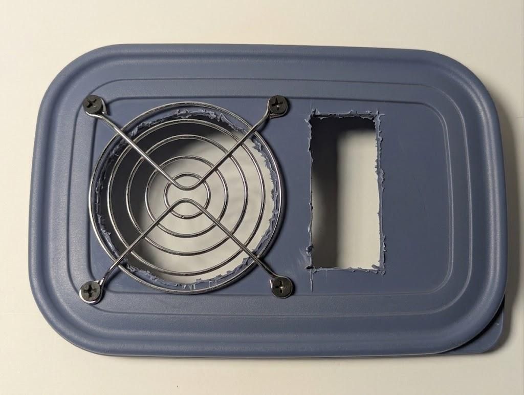
With the fan and airflow director completed, I moved on to preparing the lid of the container that would serve as the cooling chamber. I first removed the original lid and marked out two openings on it. Toward the rear of the lid, I marked a circular opening that was slightly smaller than the diameter of the fan guard. At the front, I marked a rectangular opening corresponding to the rectangular opening already made in the base of the air outlet chamber. These two openings are important because they will provide the path for air to move from the cooling chamber into the fan section.
I cut the openings using a combination of scissors and an X-Acto knife. The circular opening was deliberately made slightly smaller than the fan guard so that the guard could sit securely over it rather than simply falling through the opening. After positioning the fan guard over the circular opening, I marked the locations of its four mounting legs and drilled four small holes through the lid at these points.
These holes will allow screws to pass through the fan guard and secure it firmly to the lid. I also checked the alignment of both openings with the corresponding parts of the air outlet chamber before moving on, since a good fit here is important for keeping the airflow directed through the intended path.
Assembling the Cooler
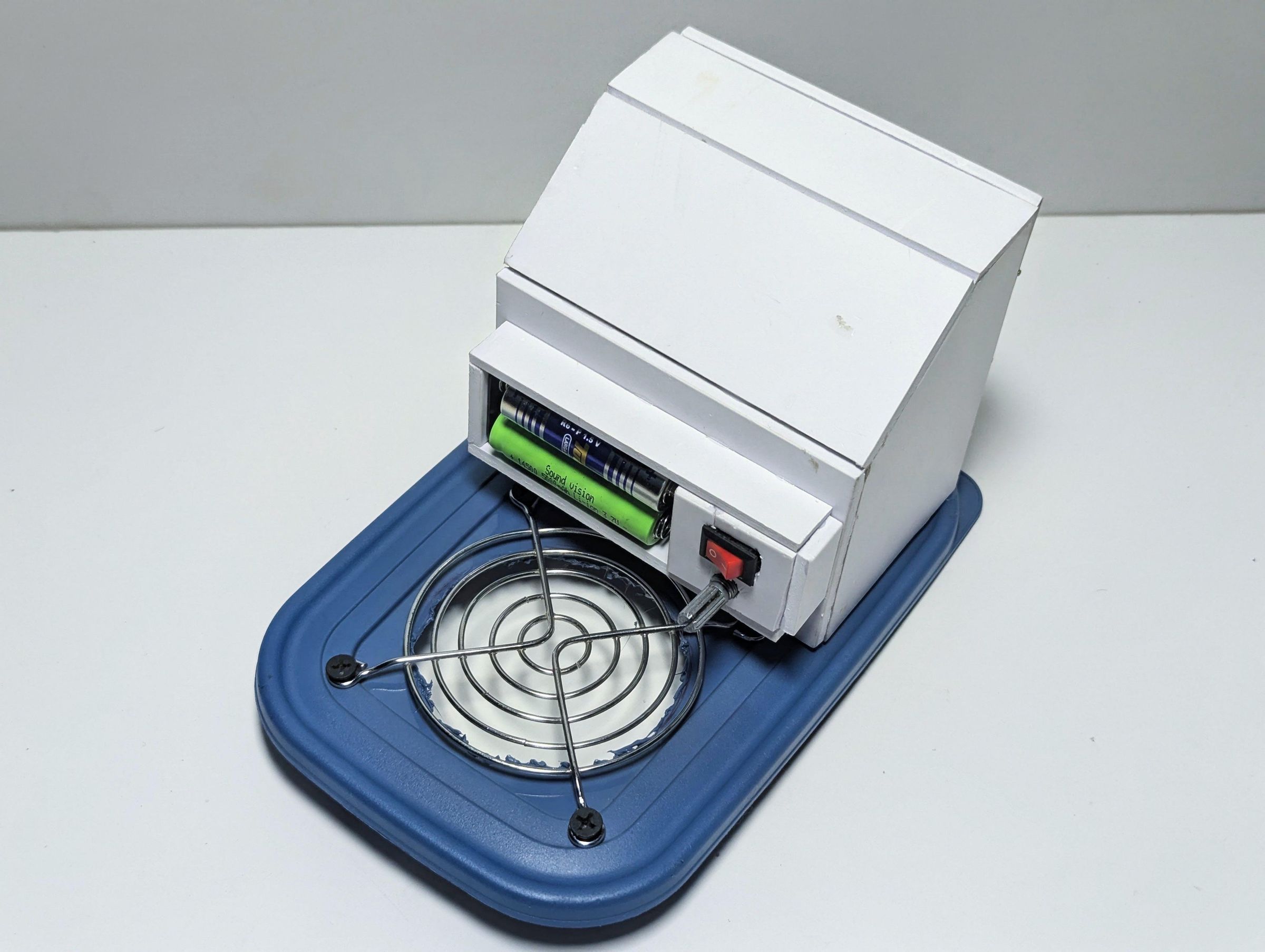
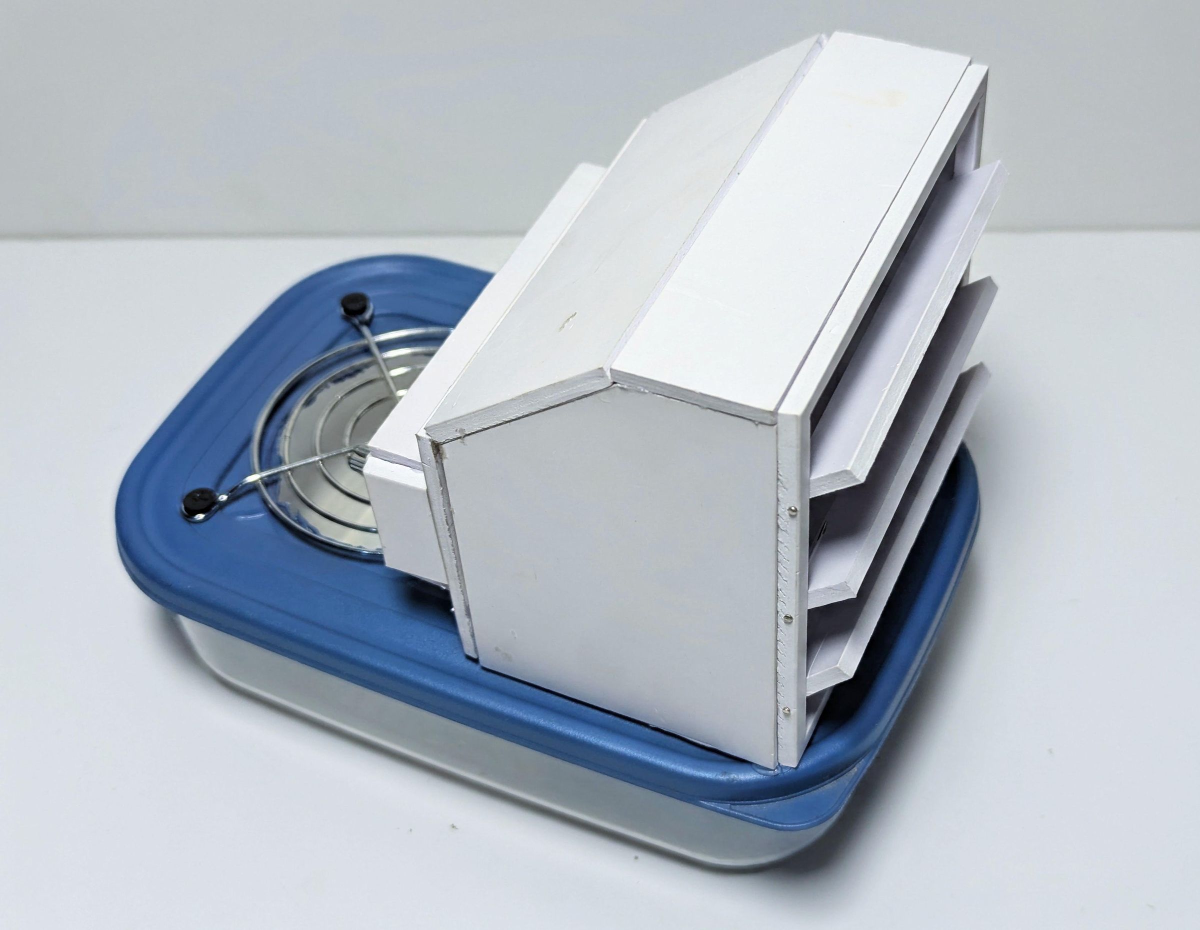
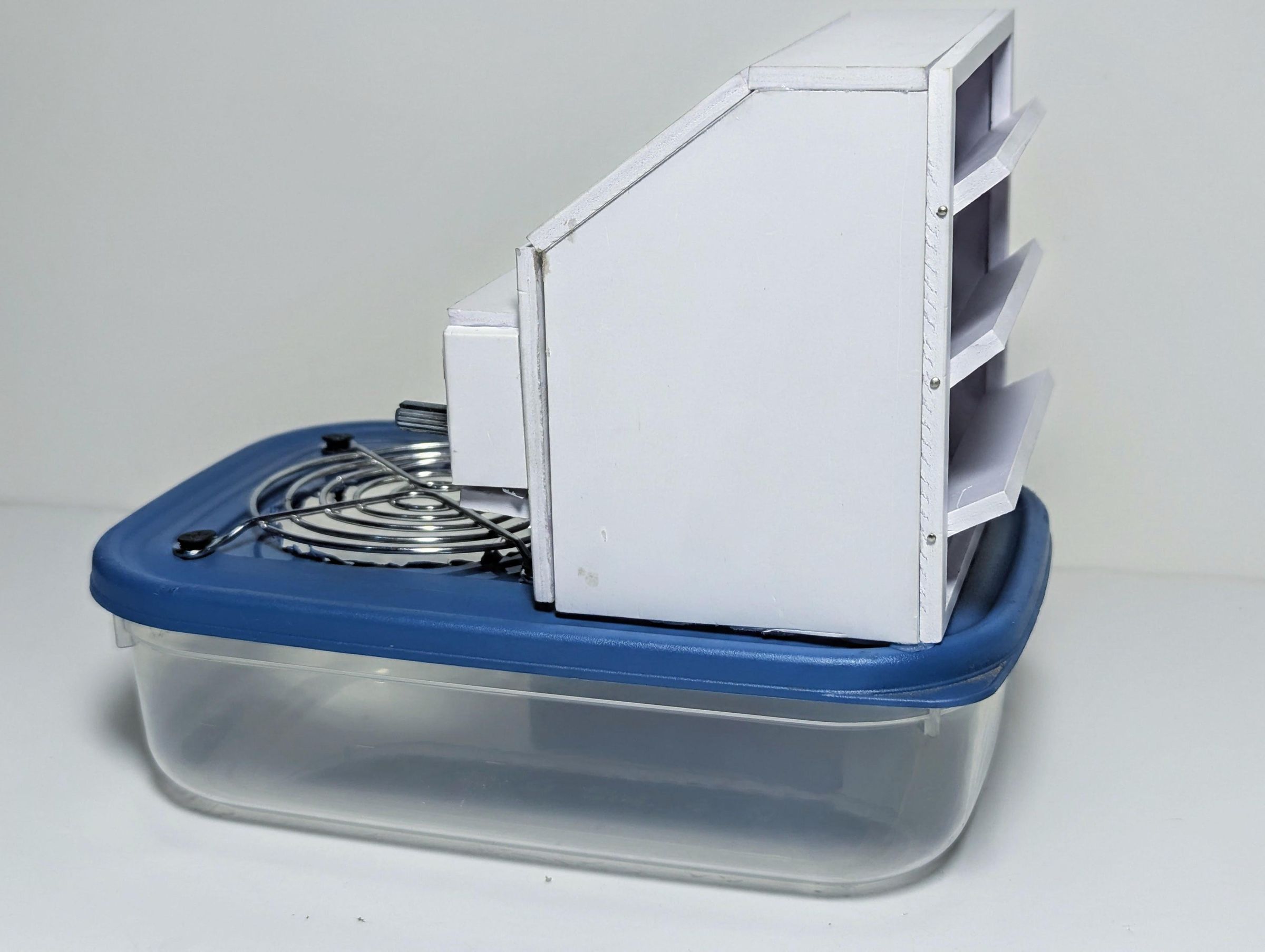
Now that the air outlet chamber and the cooling chamber lid were ready, it was time to bring the two main sections together. I applied a generous bead of hot glue around the base of the air outlet chamber, then carefully positioned it over the rectangular opening in the lid. I made sure the opening in the chamber lined up properly with the opening in the lid before pressing the two pieces together. This connection needs to be reasonably airtight so that most of the air drawn by the fan comes through the intended path from the cooling chamber rather than escaping around the joint.
With the air outlet chamber firmly attached, I positioned the fan guard over the circular opening at the rear of the lid. The four small holes made in the previous step were aligned with the mounting points of the guard, and I secured it in place with screws. The guard allows air in while preventing bigger items from being sucked into the ice chamber.
Finally, I placed the completed lid assembly onto the container. This brought together the cooling chamber, fan, motor, electronics and adjustable airflow director into one complete unit. At this point, the basic cooler was assembled and ready for the final testing and demonstration.
Using the Cooler and Final Thoughts
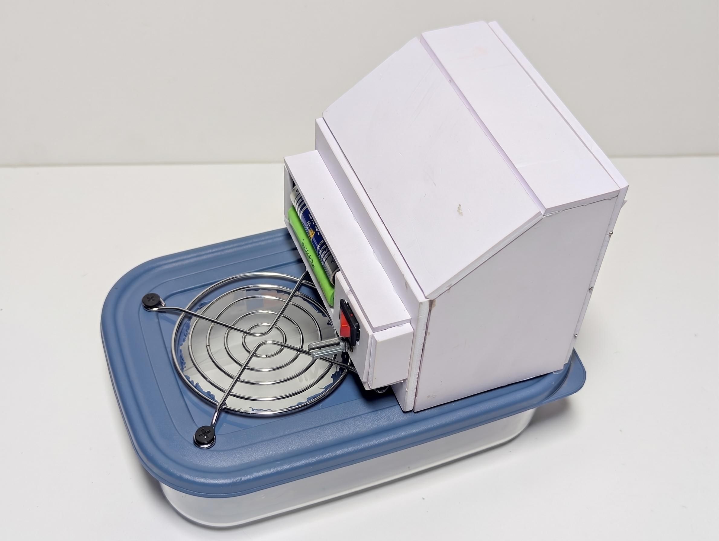
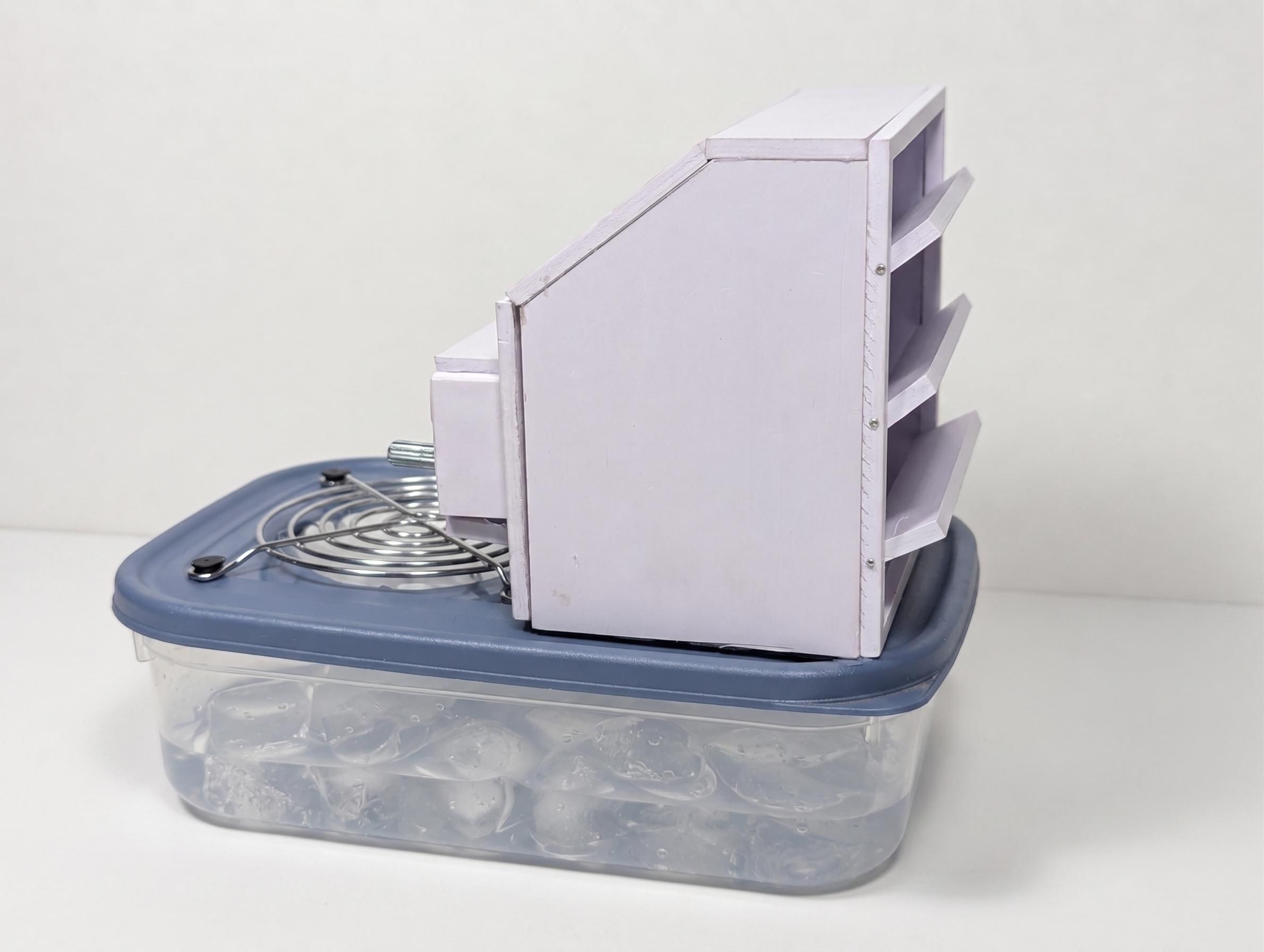
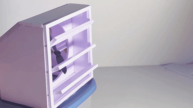
To use the cooler, I first add ice to the container until it is roughly half full. I then place the lid and fan assembly back onto the container, insert the two batteries into the battery holder and switch the cooler on. The fan draws air through the space containing the ice, where heat from the incoming air is transferred to the ice as it melts. The resulting cooler airflow is then pushed through the outlet and toward the user.
The speed of the fan can be adjusted using the control dial. The direction of the airflow can also be adjusted by tilting the three vanes on the outlet up or down. This is particularly useful because the cooler does not have a tilting neck like a conventional desk fan, so the adjustable vanes make it possible to direct the airflow toward the face or upper body without having to move the entire cooler.
One thing worth acknowledging about an ice-based cooler is that ice does not appear out of nowhere. If the ice is produced in a household freezer, the freezer has already consumed electricity and released heat into the surrounding environment while making it. From an overall energy-efficiency perspective, this means that using ice to cool a room is not necessarily better than simply using an appropriately designed air-conditioning or cooling system. This project is therefore not intended to compete with an air conditioner as a whole-room cooling solution.
Where I think this design makes more sense is personal, short-duration cooling. For example, it could be useful on a desk while studying or working, beside a bed at night, in a small workshop, or in another situation where only one person needs immediate cooling rather than an entire room. In these situations, the ice can be prepared in advance, and the cooler can provide concentrated cooling exactly where it is needed.