DIY Lithium Polymer Battery Protector
by Nirubxn in Circuits > Electronics
630 Views, 7 Favorites, 0 Comments
DIY Lithium Polymer Battery Protector


Hi, I recently built an amazing RC car. One of the main components of the RC car is, of course, the battery. For RC projects, the most commonly used battery type is a lithium polymer battery. However, due to their high energy density, these batteries are unstable and can pose dangerous hazards even with a small mistake. The issue for me is that I purchased a lithium polymer battery almost a month ago and still haven't used it yet.
As I mentioned earlier, I don't feel entirely safe having a 2.2Ah, 80C battery sitting unprotected in my RC car. You might suggest adding a protection circuit to the battery, and while that makes sense, the process of installing a protection circuit can be hazardous—at least for me. So, I decided to create a battery protector. As the name implies, it protects the battery from overcharging, overdischarging, and overcurrent.
*Note : This accessory is only good for builds that demand less than 20 A of current due to the limit of the board as well as the voltage drop on the transistors.
This protector is hot-pluggable, which means you just need to plug it into the battery, and you're good to go!
So, let us get into building one.
Supplies


First and most importantly, I will be using a 3S lithium ion battery protection circuit with a max current rating of 20 A. This BMS board has a battery balancing feature, which means, it can discharge the batteries to maintain an equal state of charge.
Next, the battery. You can use any 3S battery like this. I went with a 11.1 V 2.2 Ah 80C battery.
For connections, I used a pair of XT60 connectors and a female 4 pin JST (A.K.A battery balance) connector.
Lastly, we need some wires. Namely, 4 square millimetre wires for the battery terminals and ribbon wires for the battery balance terminals. I went with a 4 square millimetre wire pair in order to match the 12 AWG wire from the battery.
Make the Connections


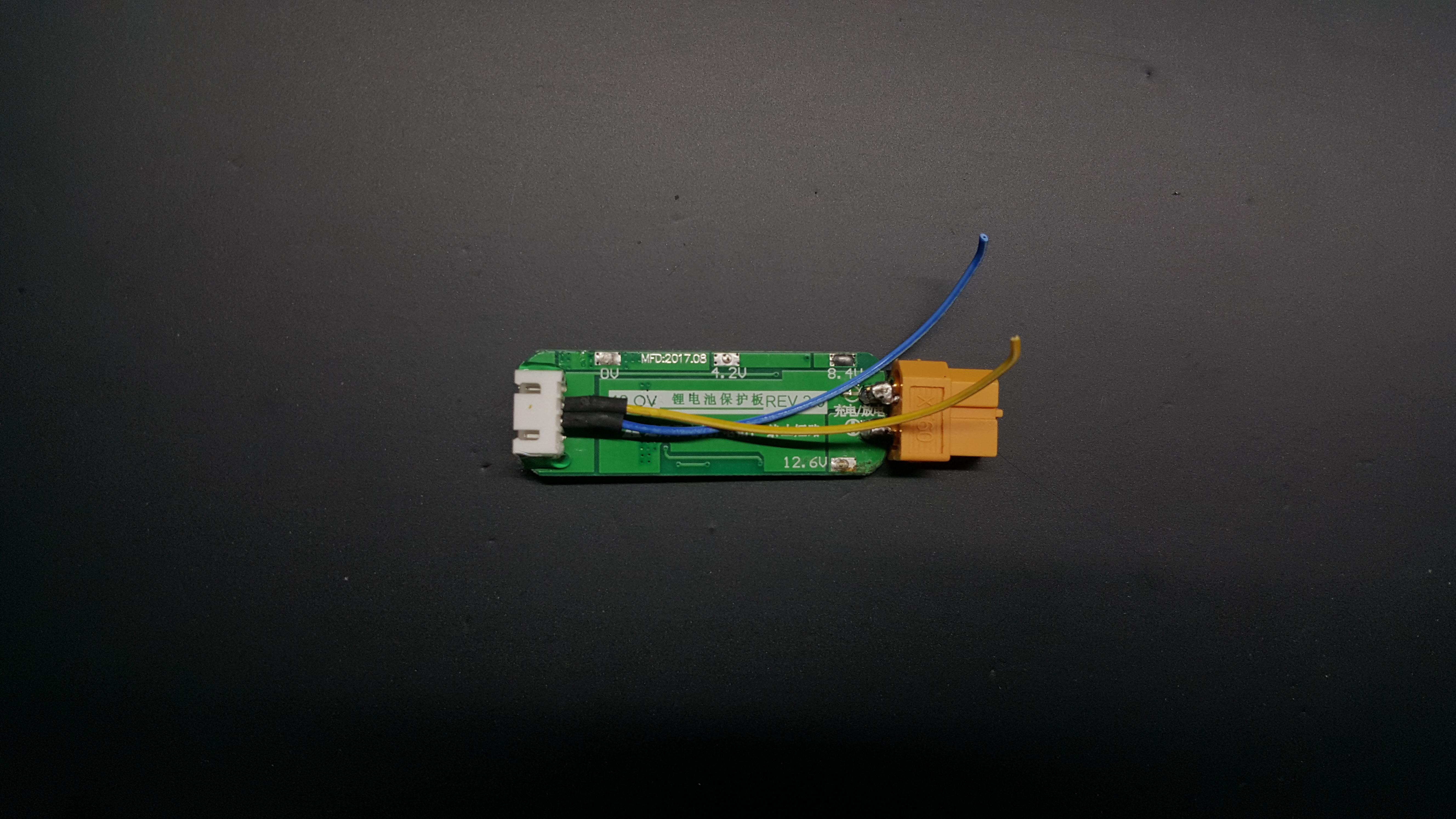
To begin, I soldered the male XT60 connector to the output terminals of the BMS on the back side, ensuring the correct polarity. Next, I soldered four wires, of which only the middle two were used. Then, I connected the yellow wire—corresponding to the 3.7V terminal of the balance connector—to the 3.7V pad on the BMS. I repeated this process with the 8.4V pad. Once that was complete, I soldered two 4 square millimetre wires to the 0V and 11.1V terminals, using black and red wires for proper colour coding, respectively.
I strongly recommend performing this step carefully, as any mistake could result in damage to both the board and the battery connectors.
Once it is done, it should look something like this. I tested this with my other battery pack as I was still afraid to try it on my lithium polymer battery and it worked.
Add the Case


Now that it is working, I did not feel like having the exposed PCB terminals to the metal parts of my RC car. So, I went ahead and designed a case in Fusion 360. I printed it with my 3D printed at a 40% infill rate and supports toggled on. After an hour, the printing was done. I somehow managed to place everything in and glue it in place. With that, the build was done. I lastly tested it with my lithium polymer battery and it worked.
With an added safety accessory, I feel much more safe driving my RC car. Thanks for reading this short Instructables. Do like and comment, and I will catch you in my next Instructable.