DIY Mini Gas Leak Detector That Also Monitors Air Quality in Real-Time
by ROBO HUB in Circuits > Raspberry Pi
1646 Views, 12 Favorites, 0 Comments
DIY Mini Gas Leak Detector That Also Monitors Air Quality in Real-Time
Hello readers in this instructables i will show you how i made this mini gas leak detection system that also monitors the air quality in real-time.
Did you ever take a moment to think that the air quality in your room which you breath is safe or not safe?
Few may say ahh! I don't smell any bad odour so the air quality of the room is just fine.
But i would say, you are wrong! some of the gases which you can't really smell are not good for your lungs.
Imagine you are working at your garage, or you are a hobbyist builder working in your own room.
Let's be practical imagine Gas spillage inside your camping tent or the smoke that comes from your soldering iron or the room freshener spray these pollute the air.
Like the above instances there are hundreds of other real life example which may lead to a decline in the air quality.
So i made this small device that alerts you when it detects smoke or gases that are not meant to be taken inside.
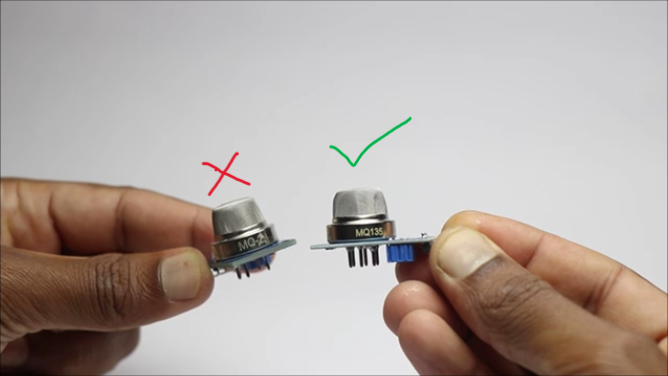
You may think, the sensor you are using looks similar to MQ2, But hold on guys this is not MQ2 instead this is MQ135.
So what is the difference between these two even though both looks the same.
MQ2 sensor only detects LPG, whereas the MQ135 that I used here can detect LPG along with many other gases like smoke, ammonia, nitrogen oxides, and alcohol vapors.
So basically this one sensor can detect so many gases, and I will be using raspberry pi pico as a controller and python codes to run this device.
Few things that i would like to tell about the MQ135 sensor to those who are new and still wondering how this sensor works.
The sensor has a small component inside that heats up when it's powered and the mesh outside covers this component completely.
Inside the mesh there is a Tin Dioxide filament, which has lower conductivity in clean air and higher conductivity when exposed to pollution.
This change will produce a signal, and the sensor sends signal to microcontroller which later is converted to readable values using the Python code and displayed on an OLED.
How does this device work?
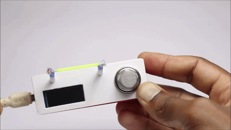
Simply connect this to a USB power source and allow few seconds(since the sensor components will heat up).
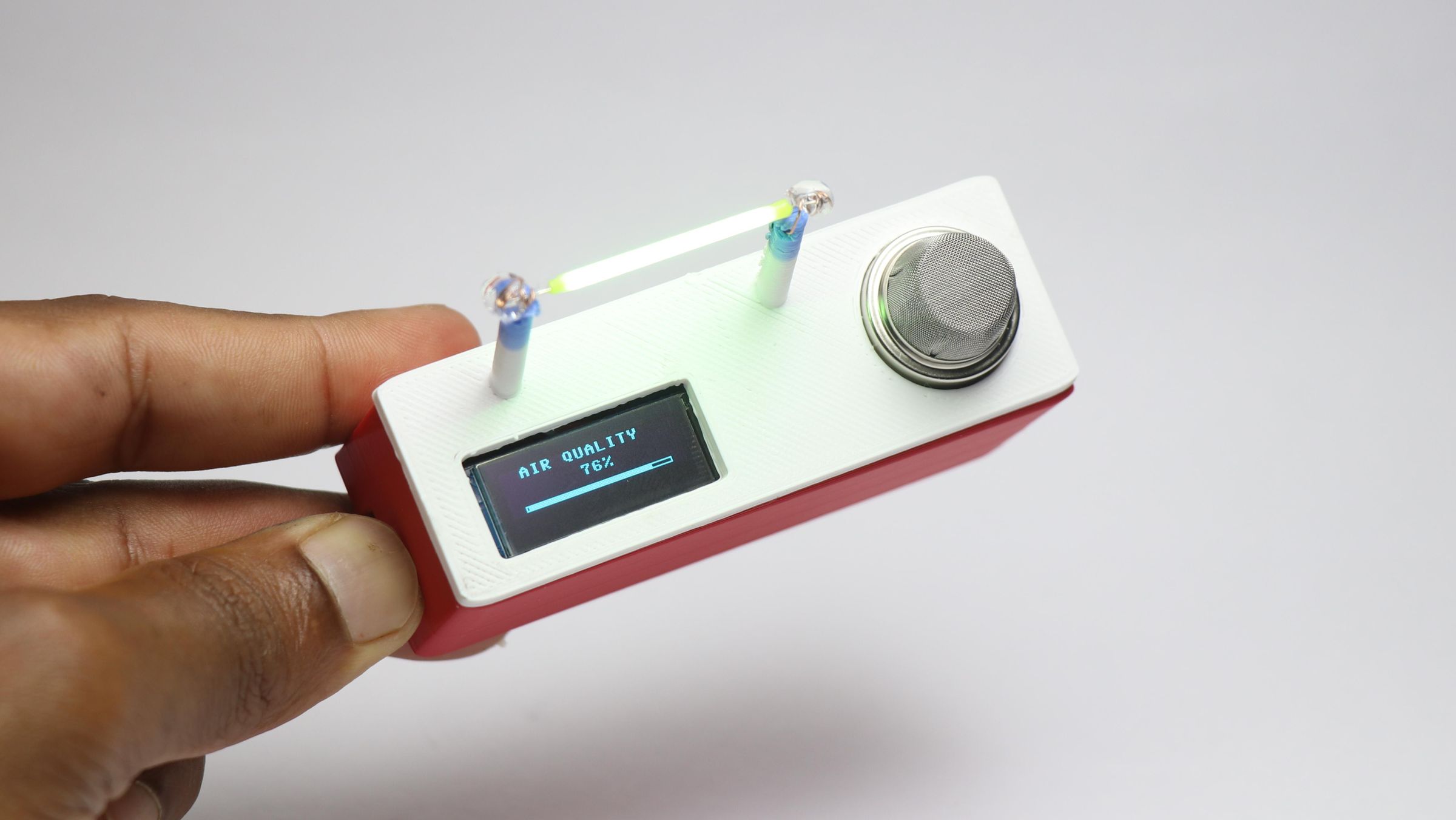
The screen shows up and the device is live now showing the air quality level and also the LPG detection status.
If the sensor detects any pollutants its real time values are displayed, and the OLED screen switches between the air quality and LPG leakage levels.
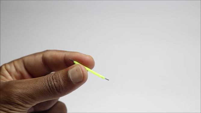
If the levels exceed then the LED blinks to alert you and here I used this Edison LED filament as an indicator.
I have made the frame using 3d printed parts so that anybody could build this device
Supplies
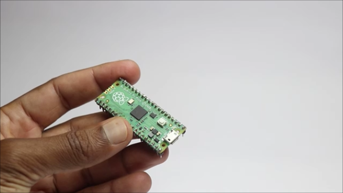
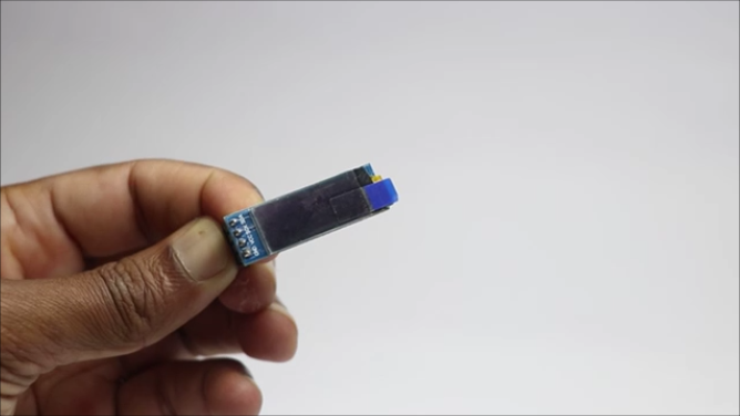

These are the materials that you need to build this project
Copper Wire(insulated)
Jumper Cables
Thonny IDE
Programming Cable
Soldering Iron
Hot Glue
3D Printer
PLA Filament
Cura Slicer
Some Time of Yours!
If you buy from the links above i will receive a small percent of sales at no extra cost to you this will help in supporting projects
Tinkercad Design
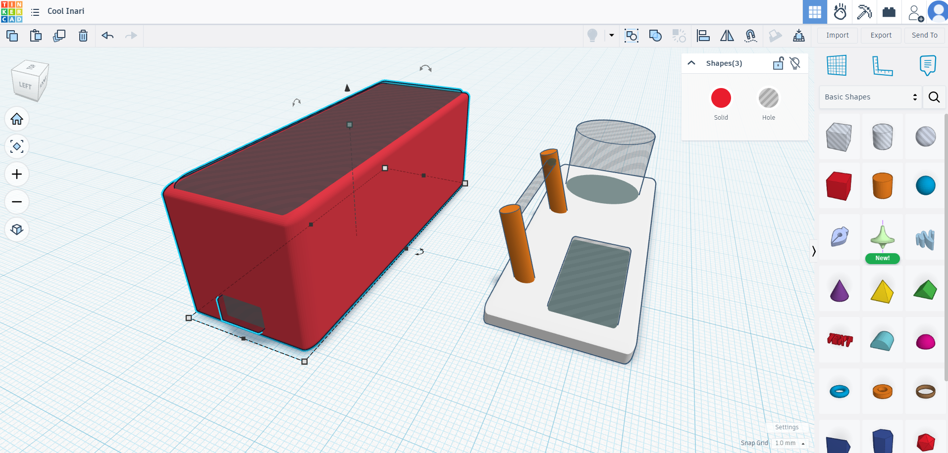
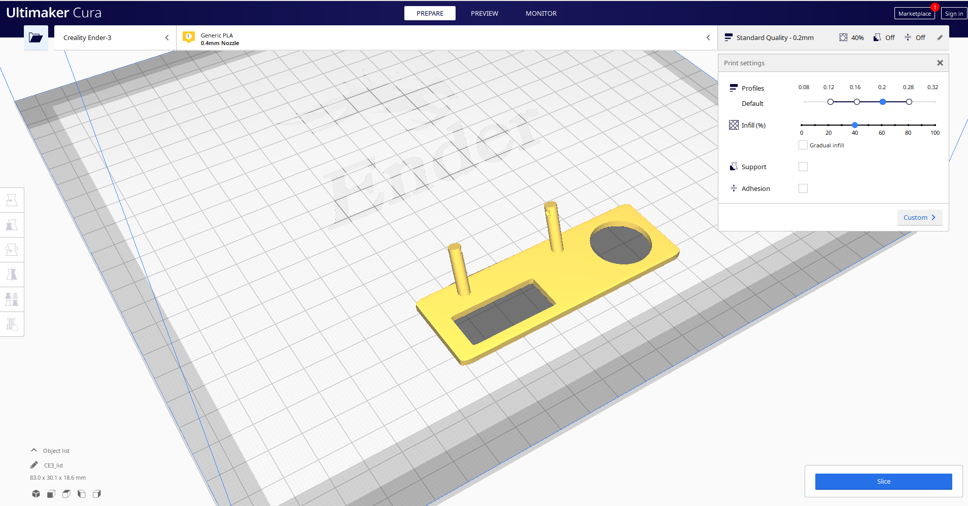
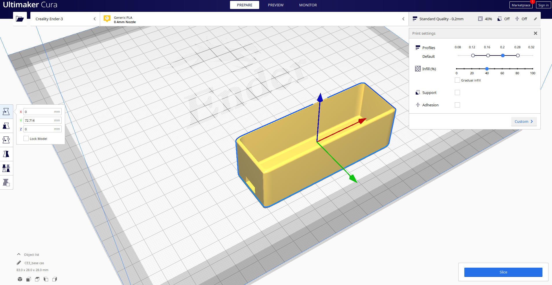
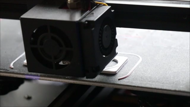
I have used Tinkercad to make casing for this project, After several attempts and adjustments i came up with this final design.
The goal of the design was to make a small yet good looking frame that will hold all the components.
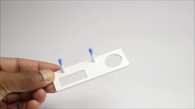
There will be 2 parts for this project, First is the base case that holds the controller and the other is the lis that will hold the sensor, Display module and the LED indicator.
Base will hold the pico board, the lid has a small hold that will help in the connection of wires from the edison LED filament to the controller board.
Since i will be powering the components from the controller board the standard size of the components were taken into account at the time of design.
You can simply use my STL files that i have given below to print your parts.
If you are someone who likes to remix my design you can do that too! Just let me know if you need any help.
After the design is complete, Export the files to slicer(i will be using Ultimaker Cura)
There is no need of any rafts or supports at the time of slicing, Just refer my settings and you are good to go.
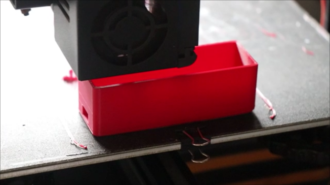
I will print the parts seperately, you can choose the filament color of your choice at the time of 3d printing.
Since the parts are small both the parts can be printed soon and there is no need of any post processing.
I will print the base with red color PLA filament and the lid with white filament since this combination looked good for this project.
Circuit and Program
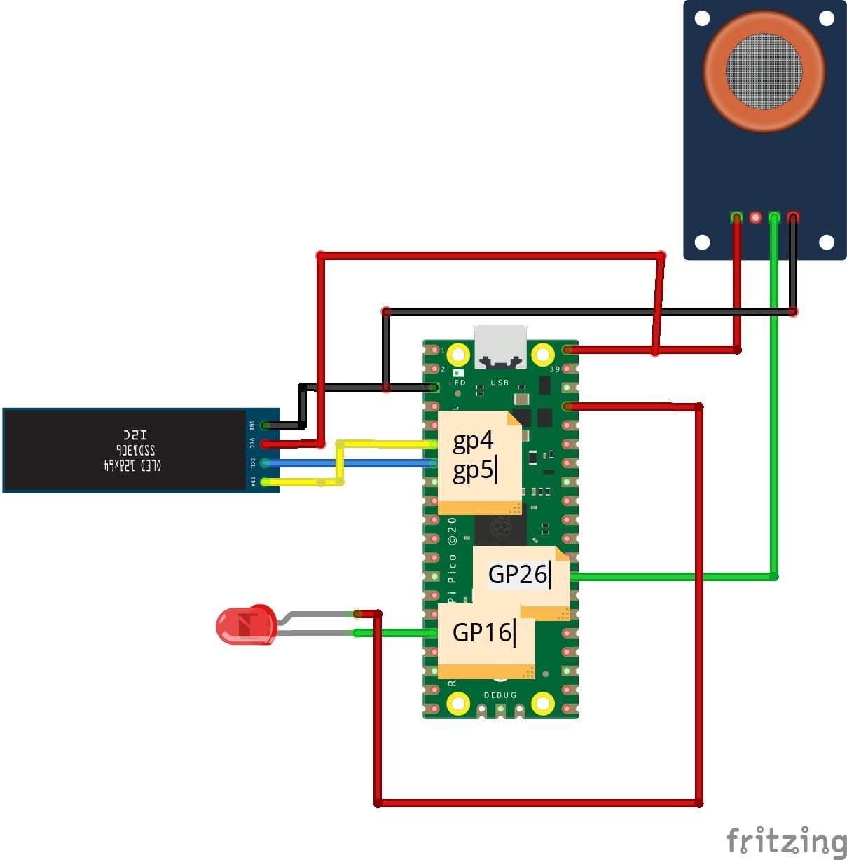
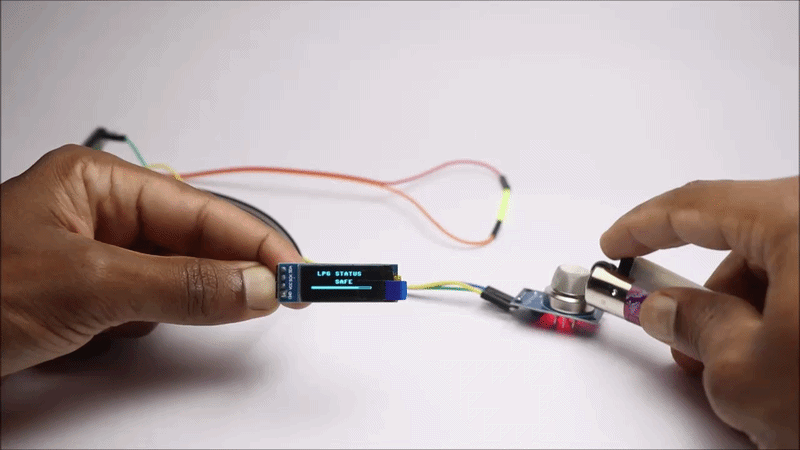


Here the raspberry pi pico will control the MQ135 sensor, LED indicator and the OLED module so only 3 parts is involved.
I will break the circuit into 3 parts so that you can understand better.
MQ135 Sensor connections
These comes with 4 pins and we are using only 3 pins
The positive and negative pins are connected to the VBUS and the Ground pins of the pico board.
The analog pin is connected to GP26(A0) on the Pico board
The Edison filament has 2 pins
Side of the pin with a tiny hole is considered as positive and this will be connected to the GP16
Other pin is considered negative and will be connected to Gnd of the pico board
OLED connections
These has 4 pins like the usual
Positive and Negative or the Vcc and Gnd connected to Vbus and the gnd pins respectively.
Scl and Sda are connected to Gp5 and Gp4 pins.
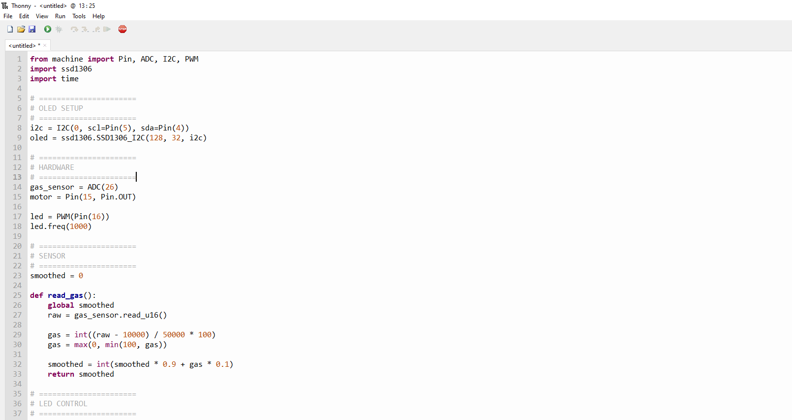
Now we can proceed to upload the program, open Thonny IDE and use the program given below.
After you open Thonny, paste the below program inside it.
Connect the usb cable to computer and while pressing the bootsel button on pico board connect the other end of usb to the Pico.
You will see the drive open up on the computer, this means that the pico board is now connected to computer.
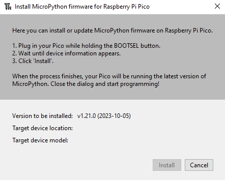
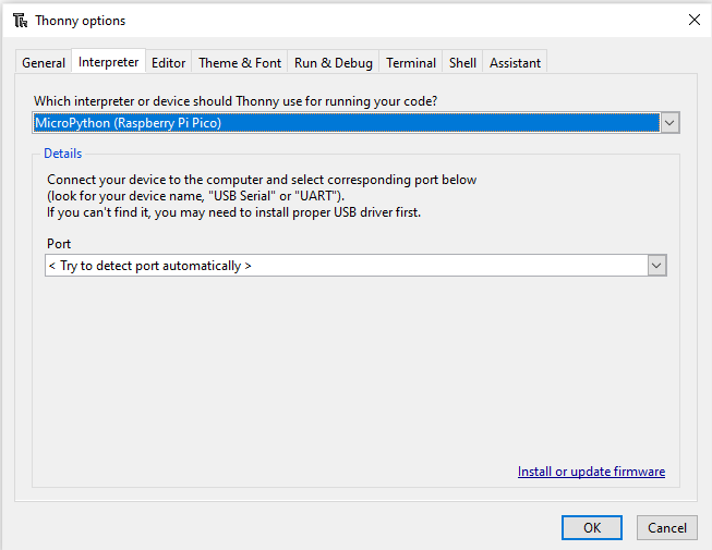
Inside thonny go to tools and then options and you will see a window go to interpreter and install micropyhon by selecting your pi pico board and the proper port.
Save the program inside your Raspberry Pi Pico by going to file then save as then select pico and give file name as main.py
This will save the python program inside your pico and now the board is ready to be used, Test it out.
The circuit will work fine! But this circuit looks messy.
You can simplify this circuit using services from JLCPCB also they provide 3d printing services!
Ordering PCB from them is very affordable and they provide fast delivery too.
If you want to track all your orders in one place you can check out their JLCONE application for both desktop and mobile devices, avail free shipping and great discount if you sign up from my link
You can show me your skills in the i made it section :)
Downloads
Installing Components

After 3d printing the parts that holds the electronics and testing the circuit for its working we can head over to the assembly.
In this step we are combining the electronics and the 3d printed hardware that makes this device practically useful.
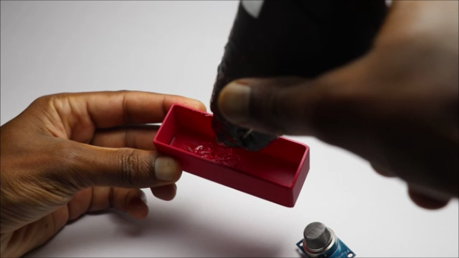
Start by adding hot glue to the base of the 3d printed bvase, You can add sufficient amount of glue because I have increased the thickness of the frame so that base will remain safe with how glue.
Now place ṭhe pico board and gently press untill a good adhesion is achieved between them and the pico sits prefectly with the pins level to the side slot.
Double check for the wire connections and if you want connect the USB cable and check if the LED and sensor is working fine.
Now the base part is complete and will head over to the lid part.
Lid has already pre made slots to hold the indicator and we will work on this later but before we will connect the sensor and the OLED here.
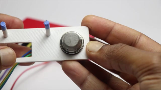
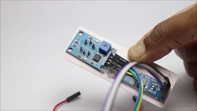
Even here you can use hot glue. Start with the oled first and after it is done coupling completely we can head over to the MQ135 sensor part.
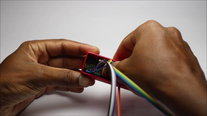
Allow to dry completely and organize the wire properly so that while connecting to the base there is no obstructions.
I have given enough room between these 2 parts so that the jumper cables will sit perfectly, This is now half complete and we can head over to installing the edison led filament and see how in the next step.
Indicator Installation
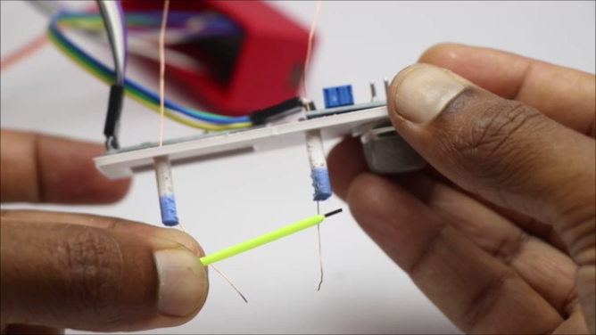
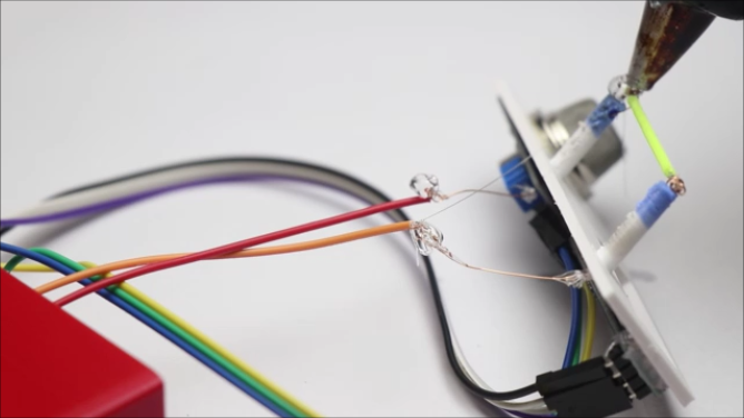
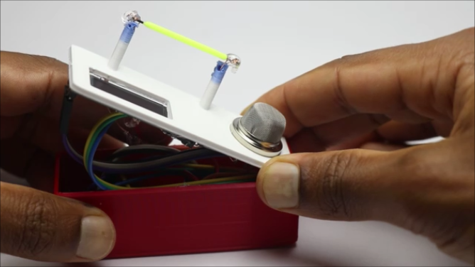
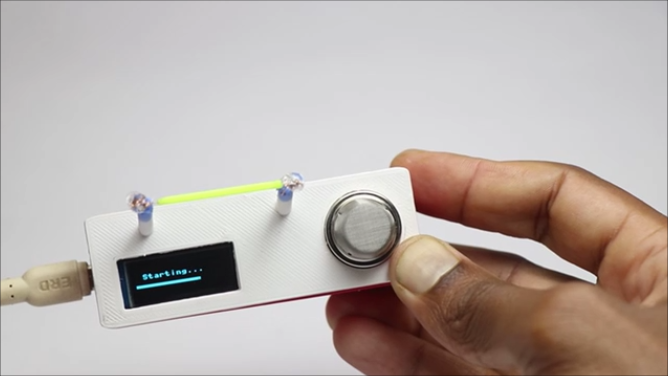
This is the important part of the device since it indicates the gas leakage and alerts you with the pulses of bright light.
I have made slots on the lid part and all you have to do is insert the insulated copper wire here and solder the end of the wire to this led filament pins.
There are positive and negative sides to this filament and you can check the pin with a small hole on this filament that says its a positive side.
I didn't solder them instead i just rolled the copper wire after removing the insulation.
Later from the other end, I removed the coating and cut the jumper cables and connected these.
Insulate the joints with hot glue or if you have heat shrink tubes even that would work fine here. Connect the end to the pico board and now carefully insert all the wires inside the base box.
To double check if everything is working fine connect the usb to the board and check if everything is working fine because after seling its difficult to recheck.
Place the lid over the bases and add small drops of super glue to couple these edges and press firmly to have a good seal.
Now the device is ready and cant wait to test it out and we can see that in the next step.
How to Use and Video Tutorial
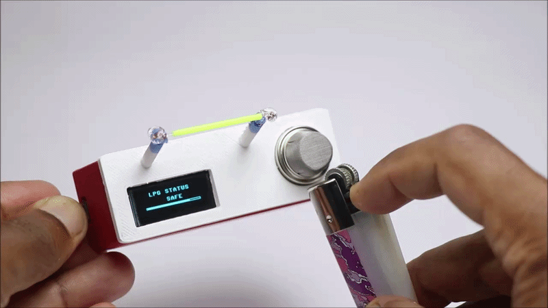
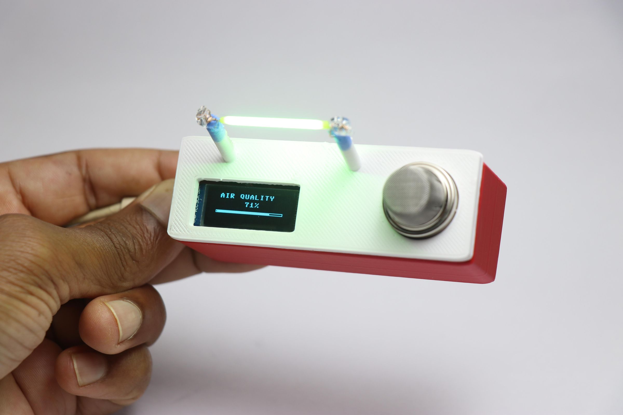
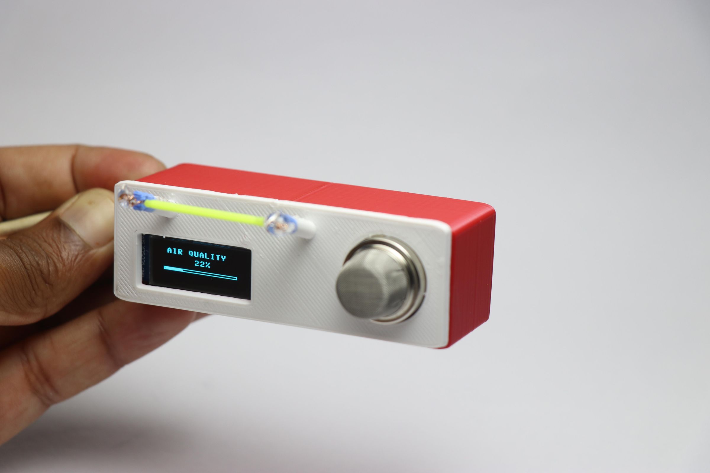
Using this device is the most exciting part of the entire project.
Simply use the usb cable to power this project, One end to the pico board and other end to power bank.
Device welcomes you with small user interface design! Later it shows that the device is ready.
The sensor heats up inside for few seconds so that it can detect the gas, Now the device is good to go.
I have made two separate screen that switches automatically every 2 seconds for displaying the air quality and the LPG leakage.
The air quality of my place that i live in is average as per the online stats and i was able to get the same here on this display.
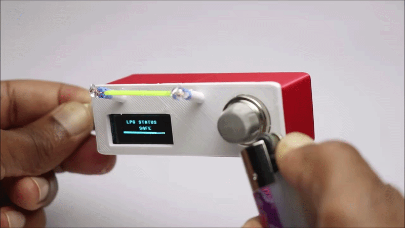
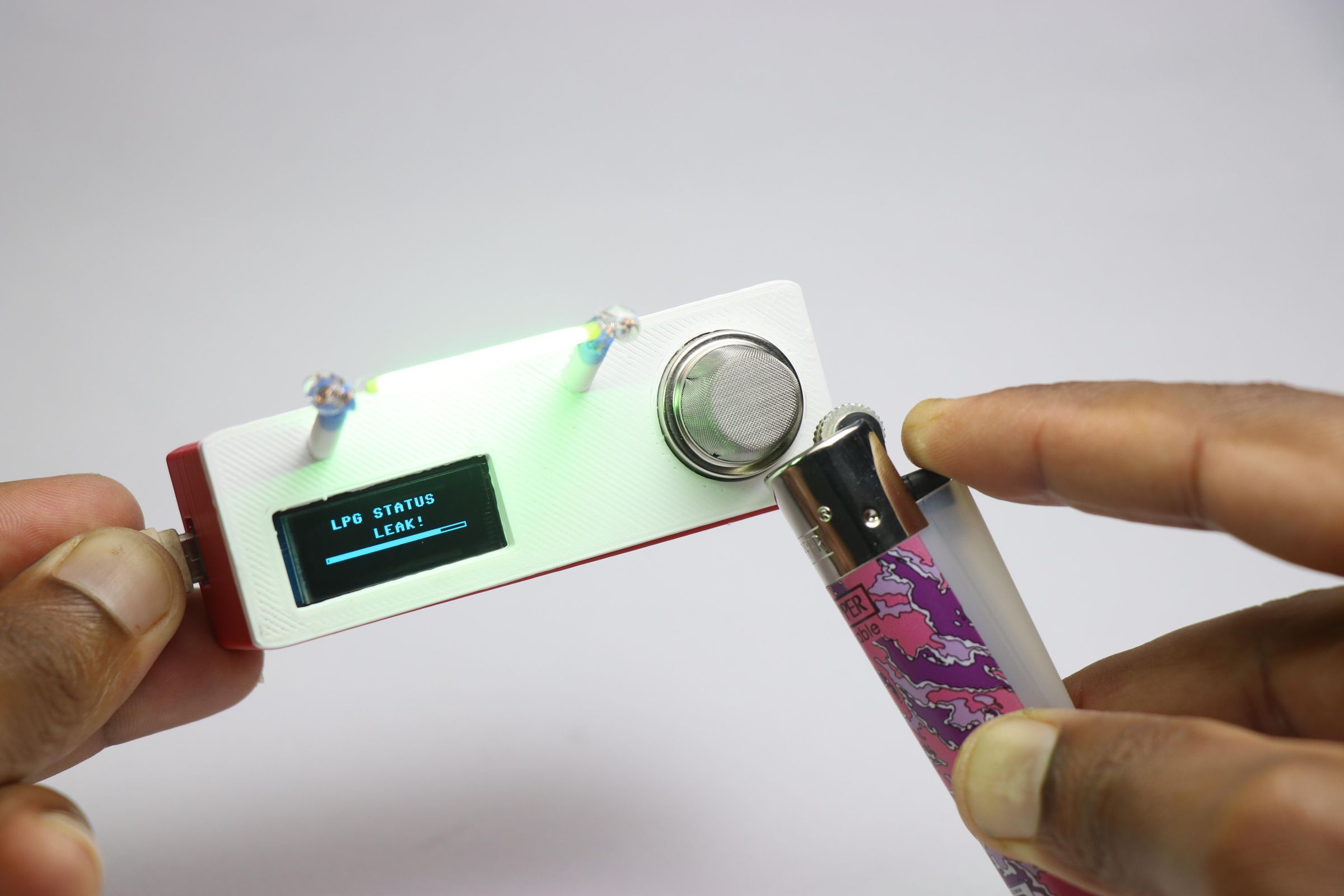
To test if the device is working fine i exposed the sensor to gas from my kitchen lighter and as you can see the device works perfectly.
Upto certain levels the indicator LED wont glow and if the leakage exceeds to high level the indicator blinks.
This is super useful in many areas of work, Hope you will try building this project.
I have also given this video tutorial where i have documented all the building steps and you can check that and dont miss to see the working part of this project.
That is all for now, Thank you for reading