DIY RGB Shelf Lights Using ESP8266 & WLED
by Jasmeeet Singh in Circuits > LEDs
6889 Views, 51 Favorites, 0 Comments
DIY RGB Shelf Lights Using ESP8266 & WLED


If you are like me, you want RGB lights in everything. Be it your mouse, your keyboard, or heck even your room.
That's why in this Instructable, I am going over the process of how I added some Addressable WS2812B LED Strips to the shelves in my room and took the Hacker vibe up a notch!
The lights use an ESP8266 with WLED installed as its main controller. WLED is a ready-to-use firmware for controlling addressable LED Lights and is compatible with chips like the ESP8266/ESP32. It comes with an intuitive android and web app that allows you to control the Lights as you want over wifi! Not only this, there are tons of animations pre-installed with WLED which you can select and play directly from the apps!
This whole system is turned on/off from a 3D Printed Lightning Bolt-shaped Latching Switch which also contains its own LED! (See the images and gif above)
Well, enough for the introduction. Let's dive right in!
Supplies


Let's start with a list of supplies:
- An ESP8266-based or ESP32-based board.
Note: I used a Bolt IOT Wifi Module since I had that lying around. But I won't recommend it since it is NOT a development board and required some tweaks to make it programmable. To keep things simple, I won't go into the explanation here but you can read more about it in my blog. Anyways, I would recommend getting a NodeMCU or the Wemos D1 Mini as the main controller for the project.
- 1 x WS2812B Addressable LED strip. I used 60 LEDs/m Non-waterproof ones.
- 1 x 5V 10A Wall Adapter
- 5 x 90 Degree Aluminium LED Diffuser Channel
- 1 x MAX4466 Microphone Module
- 1 x 3A Latching Switch with M12 Threads
- 1 x IRF540N MOSFET
- 1 x 1K resistor
- 2 x 5mm pitch 2 pin screw terminals
- 1 x 5mm pitch 3-pin screw terminal
- 2 x 3 pin JST Connector
- 2 x 3 pin JST Cable
- 1 x Perf Board (6inch x 4inch)
- 1 x Female Screwable DC Jack with M12 Threads
- 1 x Double-Sided VHB Tape
- Stranded Copper Wires (3 Different Colors) for connecting the Strips.
- M3 Self-Tapping Screws
- Heat Shrink Tube
- 3D Printer and PLA Filament. I used Blue Silk PLA for the box and White PLA for the Lightning Bolt.
- Wire Cutter and Wire Strippers.
- Hot Glue or 2 Component Adhesive
- Some Zip Ties and Wire Clamps for Cable Management
- All your Standard Soldering equipment: Soldering Station/Iron, Soldering wire, desoldering wire, Fume Extractor (If you want to build one, you can follow my other instructable)
Print and Assemble the Parts


The project has two 3D Printed Components: The Box which houses all the electronics and the Lighting Bolt for the Latch Switch.
Both of these components require 2 3D Printed models each.
The Box
- For the box, we have box.stl and box_lid.stl.
- box.stl is the main enclosure where the final circuit with all the components on a perf board can be screwed on the standoffs using M3 screws. It also contains vents on 2 faces to allow fresh air to enter and keep the MOSFET cool in case of long run times.
- You can also solder two wires to the terminals of the Female DC Jack and screw it to the box through the designated hole.
- The lid contains holes for mounting the Latch Switch, the microphone module, and for passing the wires of the LED inside the lightning bolt. It can be screwed to the box using four M3 self-tapping screws.
- Both of these files can be printed without supports but a brim is recommended to prevent warping.
Lightning Bolt
- For the lighting bolt, we have: lightning_base.stl and lightning_cover.stl
- lightning_base.stl is where we place a single WS2812B Led and secure it using some hot glue. we can then pass its four wires (VCC, GND, DIN, D0) through the hole so that can be attached to our circuit later. It also contains an indentation in the back where the latching switch can be fixed.
- The lightning_cover.stl as the name suggests, covers the LED and acts as a diffuser for the light.
- Both these parts are based on a snap-fit design. Therefore, after fixing the LED in the base and completing the wiring, the cover can just be pushed over the base and pressed gently.
- Printing these parts is pretty straightforward and requires no supports or brims. Using White PLA is recommended for the Cover for best results but you are free the experiment with anything else!
Installing the LED Strips and Wiring Them Up


.jpg)


Some parts of this step may depend on where and how (configuration) you want to install the LEDs. I will explain the process according to my configuration but will try to keep it as general as possible.
- First, you need to cut the LED strips to the correct length. Since each channel is 1m in length and I am using 4 channels, I cut 4 sections of 1m length each out of the LED strip. For the strip I am using, this translated to 60 LEDs per section.
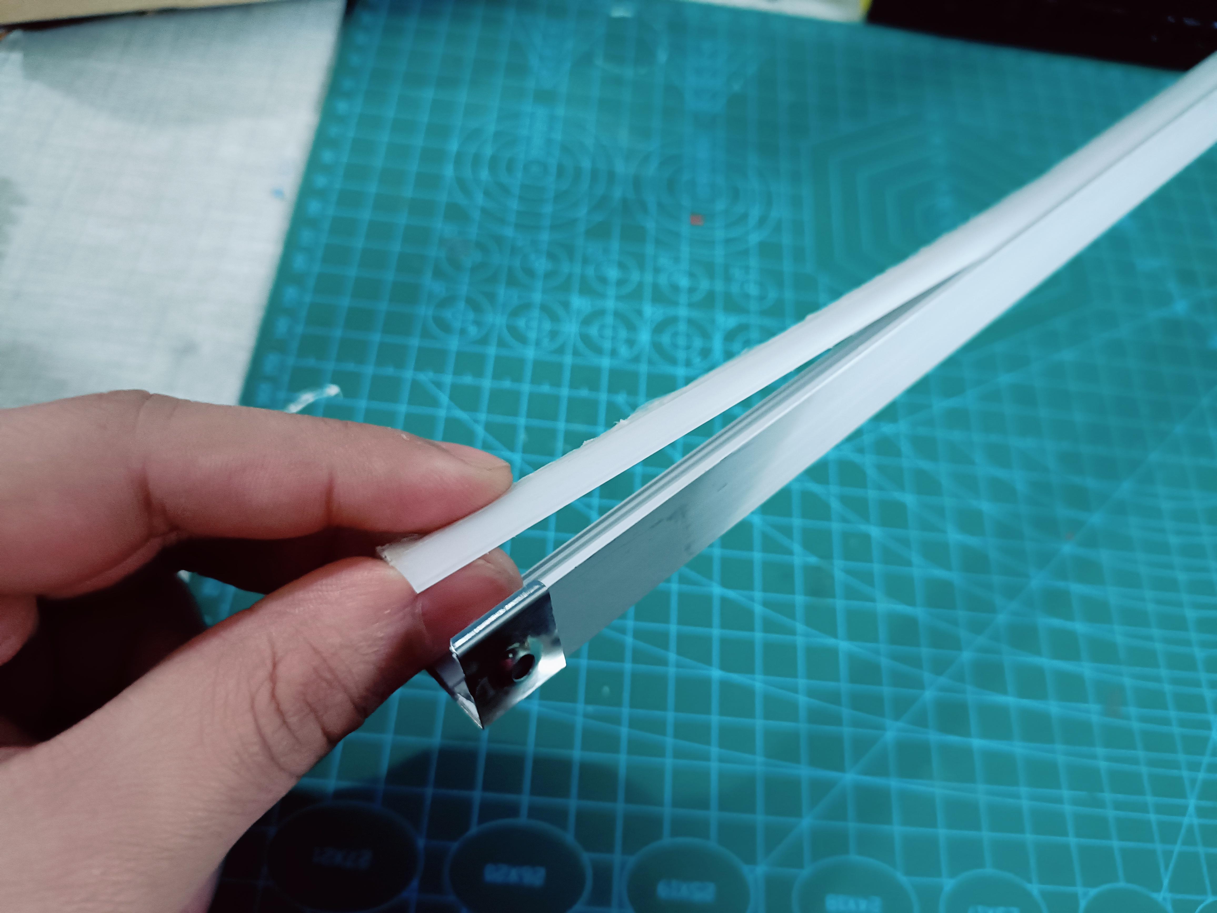
- Now remove the end caps from the diffuser channels and very gently start pushing the diffuser out of the channel using a finger. Do this slowly and gently to prevent the diffuser from breaking.
- After the diffuser is out, just clean the insides of the aluminum channel with a wet wipe to get rid of any dust. This will help LED strip adhere better to the channel. Do this and the previous step for all the channels.
- Now you can move on to soldering wires to the pads at the ends of all the previously cut LED strip sections as required. Keep in mind the data flow and power distribution while deciding the wiring for your setup. You can find a wiring diagram for my setup in the images above. Make sure the wire lengths are adequate enough to join the different sections together in your setup. For example, in my case, I cut the wires to length beforehand such that I could create connections between different shelves.
Note: Powering long LED strips in series might lead to potential drop along the way leading to dimmer LEDs towards the end. Therefore, I decided to power the right shelves and left shelves parallely.
- After this, you can move forward with sticking the LED strip inside the channel. This can be done simply by using the adhesive at the back of the strip but I would recommend using a few evenly-spaced drops of hot glue throughout the channel just completely get it fixed.
- After this was done, I went on and connected the LED strips in the channels together by soldering the required wires. Now it might not be necessary to do this beforehand in your case but I had to do it as it would be really difficult to solder wires and connect the channels after they have been fixed on the shelves. Here make sure to insert the endcaps in the wires before soldering.
Make sure to not get any hot glue in the place where the acrylic diffuser gets inserted in the channel.
- Now you can put the diffuser back on the channel. Just insert the ends of the diffuser in the channel first by gently pushing and bending. After that is done it will be secured and you can move on by pushing the edges very gently. If you feel confused, you can find tons of videos online that can show you how to install LED diffuser channels. After reinserting the diffuser you can close the channels with the end caps. You can remove any protective film that is on the diffuser.
- To fix the channels, I used double-sided VHB tape. I simply stuck small strips of double-sided tape on the back faces of the channels and after removing their covers fixed them under the shelves.
The Electronics


The circuit can be divided into 2 main sections:
- The circuit to program the ESP12-E module on the Bolt IOT Module
- The connections of the LED Strip with the ESP module, the Latch switch, and MOSFET to toggle the LED power
The first section is only required if, like me, you are using the BoltIOT (or similar) module or even a standalone ESP12-E module. Since a NodeMCU or Wemos D1 Mini are more common ESP-12E boards and I recommend using them, I won't go over the details of this section of the circuit in this instructable to keep things simple. But if you want to understand how it works, you can read about it in my blog.
Moving on to the next section of the circuit, I have attached a schematic in the images. You just have to follow the schematic and make the connections as required and you'll be good to go!
The following GPIOs were used from the ESP:
- GPIO13 --> LED data signal
- GPIO12 --> Latch Input
- A0 --> MAX4466 mic module output
Taking the latch input is not compulsory. I just did that in case I need to track the state of the MOSFET in the future.
After the circuit is done, you can move on to WLED installation and setup.
WLED Installation & Setup


This is the final step to getting your lights up and running with cool animations! For this step, there are already great resources that you can follow including official WLED documentation. Below I have provided a list of all the resources I referred to for this step:
- Official WLED installation guide
- Blog on getting started with WLED with ESP8266
- WLED setup on NodeMCU YouTube video by Chris Maher
- YouTube for a demo of various animations that can be enabled through the WLED App
A brief description of the steps I followed can be listed as follows:
- I connected the ESP to my laptop using a USB and installed the latest version of the WLED firmware on it using the Web Installer. After installation, make sure to reset the ESP once.
- The ESP then creates its own network with the name WLED-AP and password wled1234. You can connect to this network on your laptop or PC and then open the 4.3.2.1 page on your browser. Then you can enter your Wifi details and complete the device setup on that page.
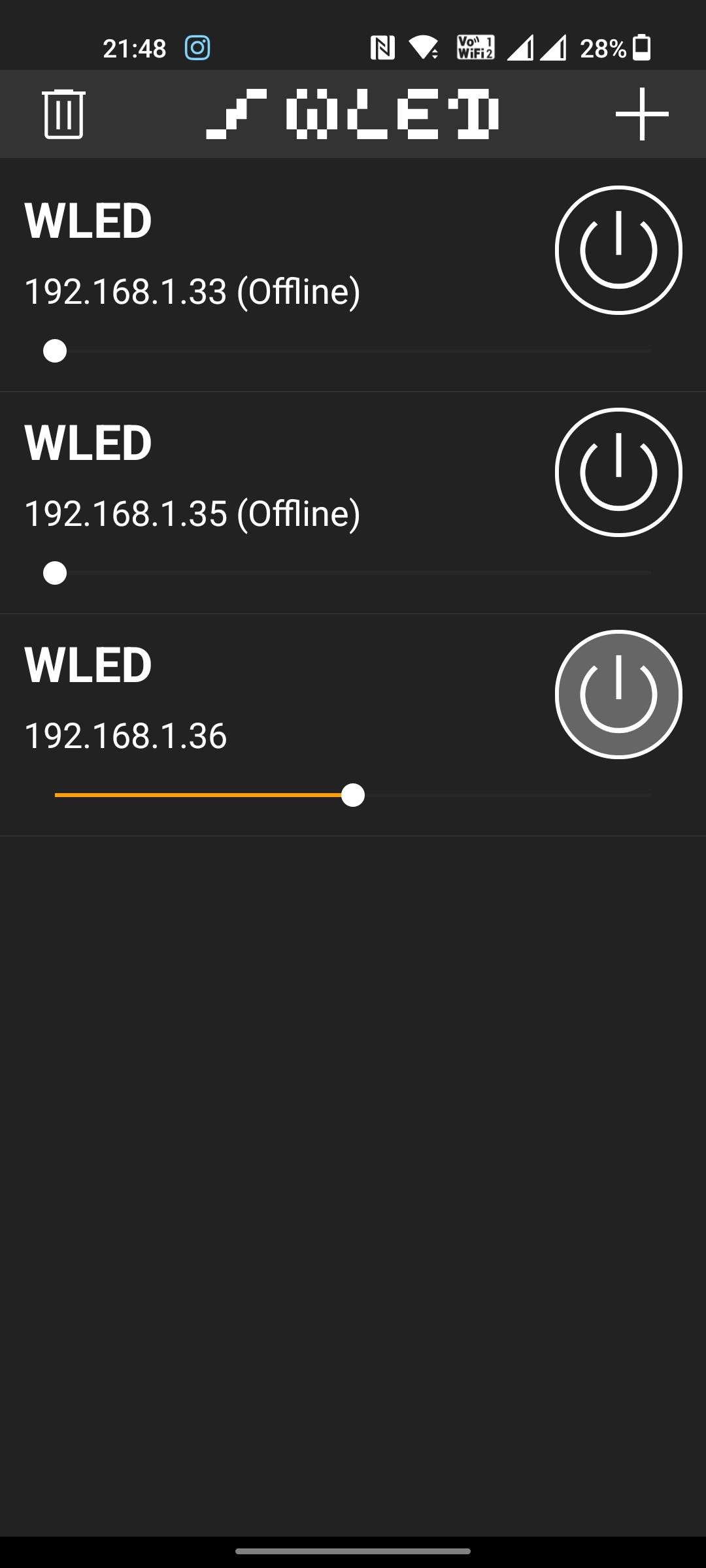
- You can then install the WLED Android App and fire it up. Make sure your phone and ESP are connected to the same Wifi network. This will allow the WLED app to automatically discover the ESP device on your network and connect to it. After opening the app click on the '+' icon and then press the 'Discover Lights' button.
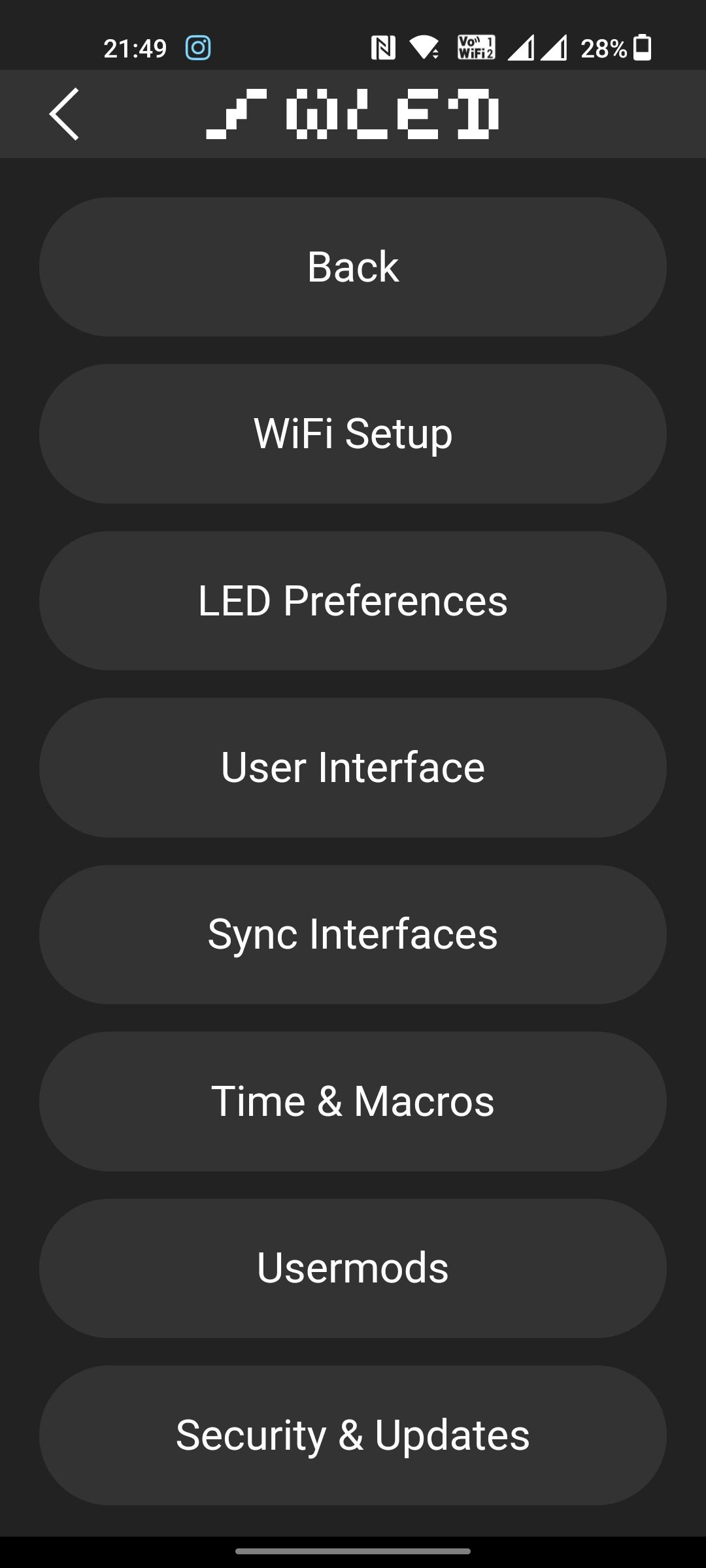
- Then in the app, head over to the config tab and then the LED preferences option. There enter the values like the Number of LEDs, GPIO, max allowed current (calculate by taking 60mA per LED) etc. in the Hardware Setup section.
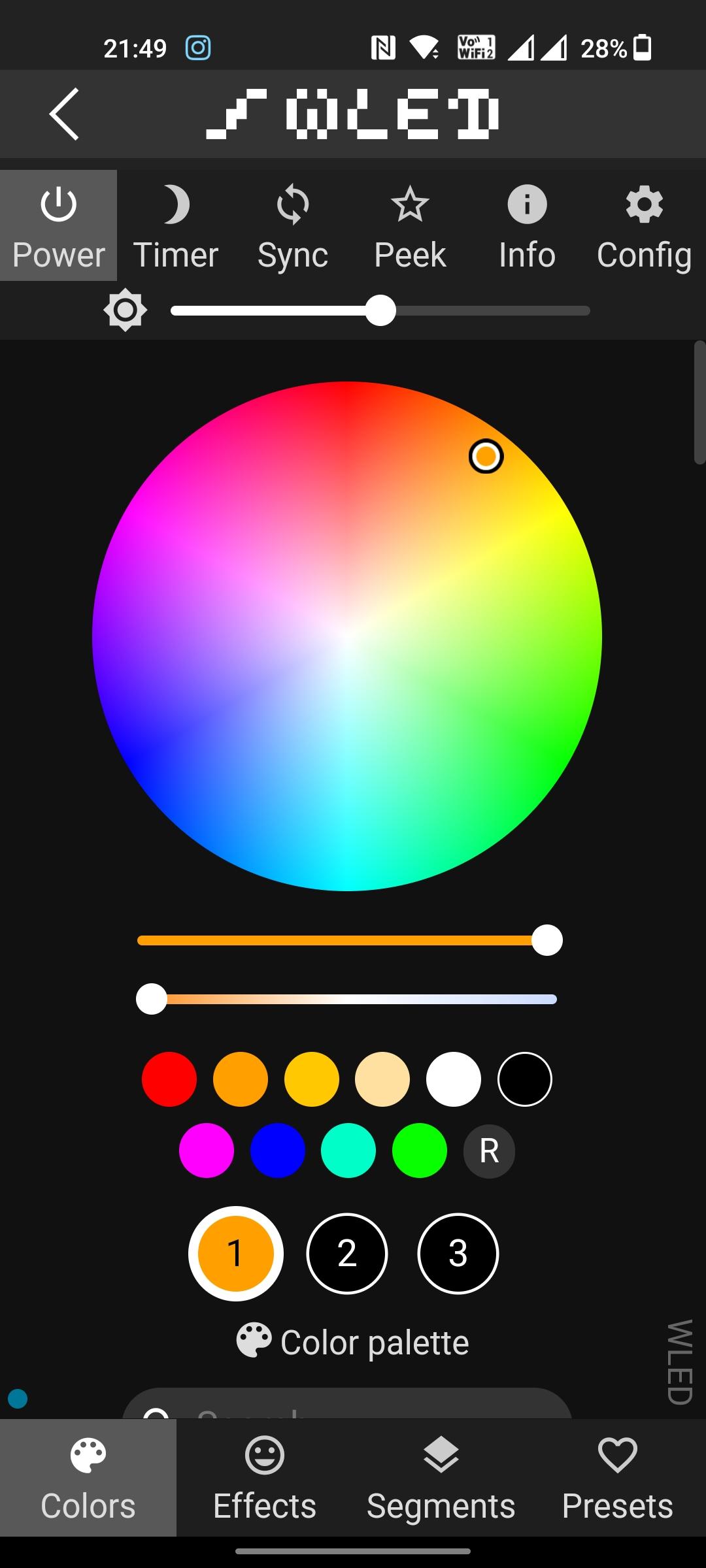
And that's it! That's all you need to do for the WLED setup. You can now move on to playing with different colors and animations!
By default, the WLED version of the ESP8266 does not support sound reactiveness but the setup can be done using LedFx which is a future part of the project. If you are using an ESP32, then you are in luck as the sound-reactive version of WLED is supported for it! You can see its setup here.