DIY Remote Controlled Water Gun Robot
by CroissantPoisson in Circuits > Robots
361 Views, 2 Favorites, 0 Comments
DIY Remote Controlled Water Gun Robot
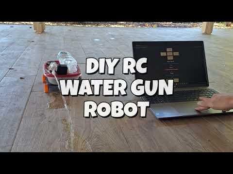
Last summer, my friends showed up unannounced at my door and ambushed me with water guns. This summer, I made sure that I would be prepared.
Water guns are a summer staple for kids. Many people have a core memory of running around their lawn, mercilessly spraying their friends. With the constant streams of water flying across the battlefield, a hot summer day becomes much more fun and refreshing.
As a college engineering student, though, I don’t have as much energy to run around as I used to. That’s when I came up with the idea for the water gun robot: a remote-controlled robot that could spray my friends (and plants) for me.
Supplies
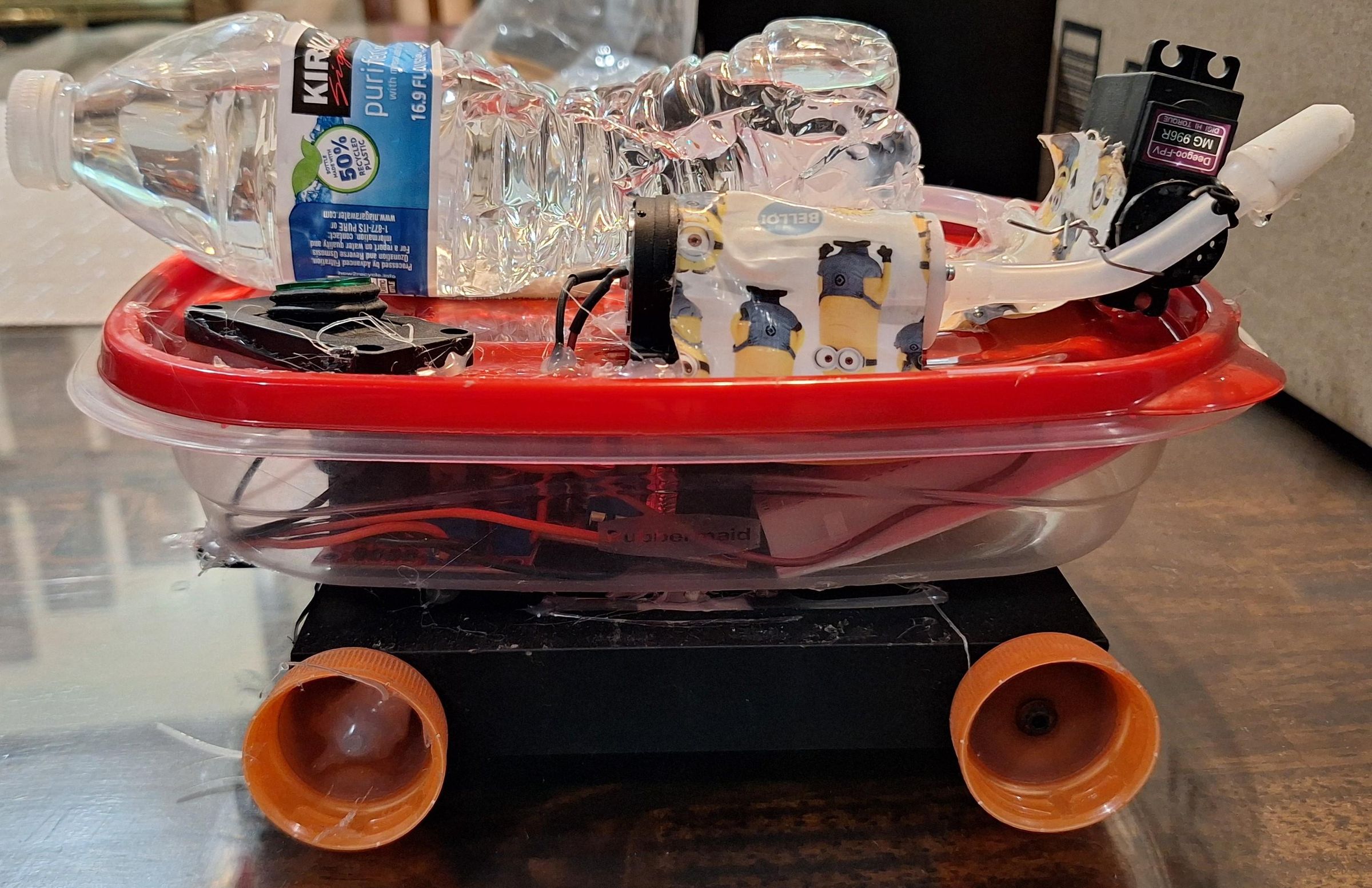
Electronics:
2 Drive Motors Amazon
Servo Amazon
Esp32 Amazon (note: any esp32 should work with minor code modifications)
Water Pump Amazon
Battery Amazon
Buck Converter Amazon
H Bridge Amazon
Waterproof Switch Amazon
Electrical Items:
Breadboard Amazon
Wires Amazon
Electrical Connectors Amazon
Power Distribution Board Amazon
Solder Amazon
Robot Body:
Water Tube Amazon
Hot Glue Gun Amazon
Duct Tape Amazon
Nuts and Bolts Amazon
Food Container (Found in Kitchen) Amazon
Plastic Water Bottle (Found in Kitchen)
3D Printer (Optional, see step 2 for DIY alternatives)
Software
Arduino IDE arduino.cc/en/software/
Connecting the Electronics
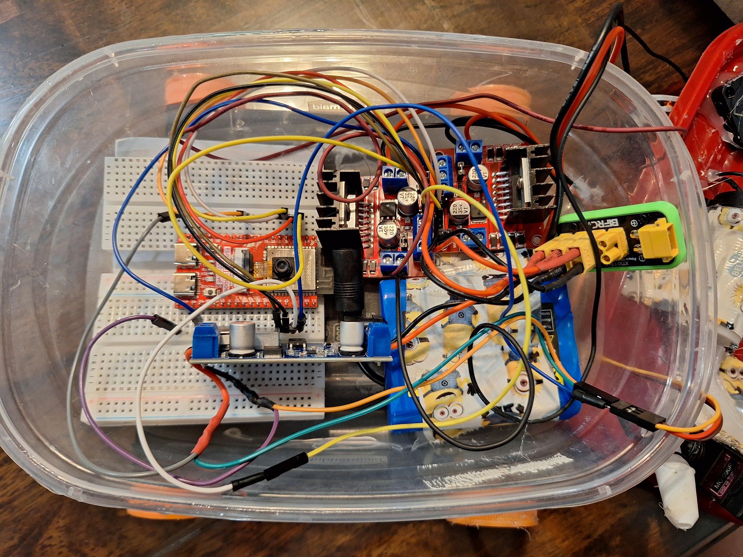
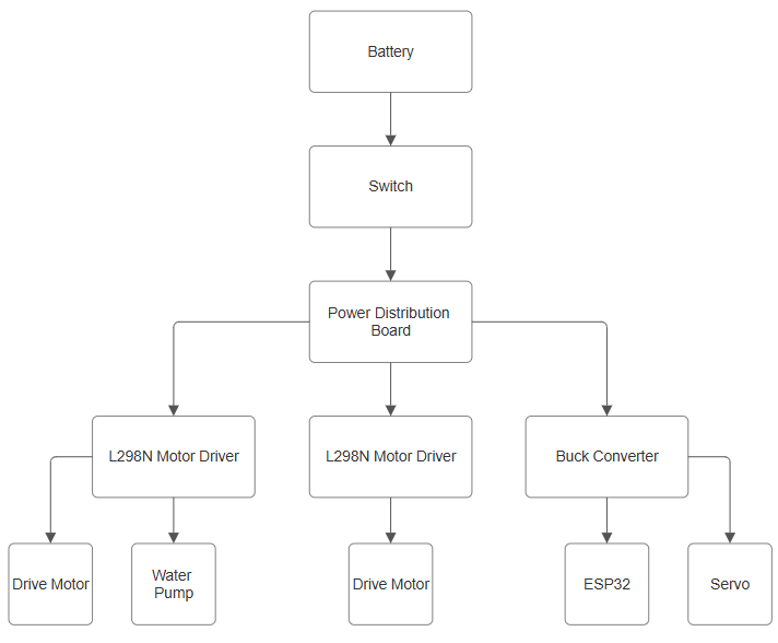
Each electronic does a simple task, such as pumping water or receiving a signal. By integrating all these electronics together, we are able to create a sophisticated robot.
To combine these electronics, we used XT 30 connectors. These provide ease of assembly and secure connections. The connectors can be bought pre-attached to wires, or you can solder them yourself.
Water and electricity obviously don't mix, so we will eventually put these components in a waterproof food container.
Connection 1: Battery to switch
The switch connects the battery with the rest of the electronics. Flipping the switch will turn the robot on or off.
Connection 2: Switch to power distribution board
This board reliably distributes power to the rest of the electronics.
Connection 3: Power distribution board to L298N (x2)
Connect the 12V and GND of the L298N motor drivers to the power distribution board. Then, use the screw terminals to connect the motor drivers to the pump and drive motors.
Connection 4: Power distribution board to buck converter
The ESP32 and servo are rated for 5 volts. Since the battery is around 12 volts, we use a buck converter to efficiently and safely output 5 volts.
Connection 5: Buck converter to servo
Connect the power and ground pins of the servo to the output side of the buck converter.
Connection 6: Buck converter to ESP32
Connect the output of the buck converter to the 5V and GND pins of the ESP32.
Wiring the ESP32
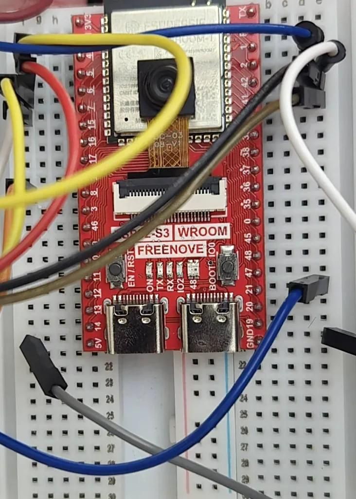
The ESP32 will be sending signals to all of the motors. While there are a lot of pins on the ESP32, some of them have other functionalities, so it is important to check the pinout diagram of your ESP32 board. We placed the ESP32 on a breadboard to make simple electrical connections.
For this step, we will connect the ESP32 pins to the motor drivers and servo. Jumper wires create an easy connection between the breadboard and electrical components.
Making the Platform
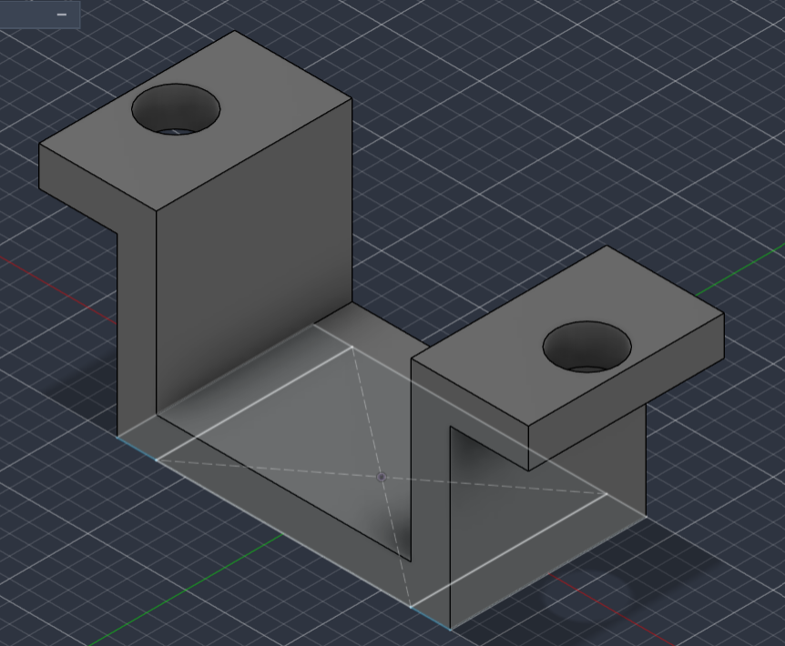
Our 3D printer broke while making this project, so we decided to embrace the indominable Instructables spirit of DIY and used items around the house to replace most of the 3D modeled parts. If you do not have access to a 3D printer, common substitute materials are also listed. Otherwise, the 3D models are attached at the bottom of this step.
Robot Body (1x)
Platform that holds the rest of the robot and provides attachment points to the motor and wheels.
DIY replacement: cardboard box - Find a cardboard box close to the size of the food container and cut holes to match the body model.
Wheels (4x)
Circular parts with a hole to fit a D shaped shaft. There are two cad files of wheels below. One of them is for the wheel connected to the motor and the other is for the driven (no motor) wheel.
DIY replacement: bottle caps - Cut holes in the middle of the holes to fit the shaft. Then, use hot glue to connect the cap with the shaft.
Shaft (2x)
Provides an attachment to the driven wheel while spinning freely.
DIY replacement: nut and bolt - Place a bolt through the driven wheel and body. Then, screw on a nut on the other side.
Motor Holders (2x)
Secures the motor to the body. Includes holes for nuts and bolts.
DIY replacement: zipties and hot glue - Secure a zip tie through the holes around the motor. Then, stabilize the connection with hot glue.
Note: These parts are designed to be friction fit. Some sanding may be required if the parts print too large.
Programming and Controls
3. Programming and Controls
Using the Arduino IDE, we programmed the motor, servo, and pump controls in C++. To use this program on your own, download the code below and replace the WiFi credentials and pin numbers.
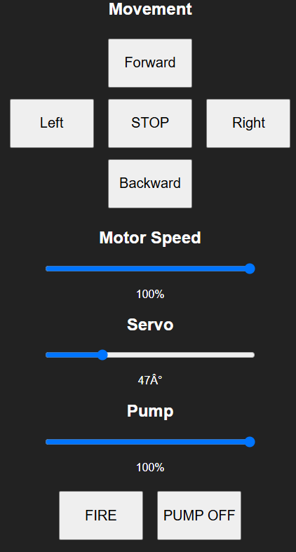
We used a web server to allow the PC to send commands to the ESP, which tells the ESP to move, adjust its water gun, spray, etc. This requires use of the Wifi and WebServer libraries, which in turn require the network information.
NOTE: make sure to replace ssid and password with your own network credentials
After obtaining the pin numbers for the components, we created functions that we wanted the robot to execute (e.g., moveForward, setPumpPower).
Pin numbers as global constants
Examples of functions (see code for all functions):
Create functions to process the commands sent by the computer.
Create an if-else if statement chain to relate each command to a function
Create the control page website
Initialize and set up motors, servo, pump, Wi-Fi connections.
Create the loop that runs the program.
Note: You may need to install the libraries from the Arduino IDE Library Manager.
Downloads
Putting It All Together
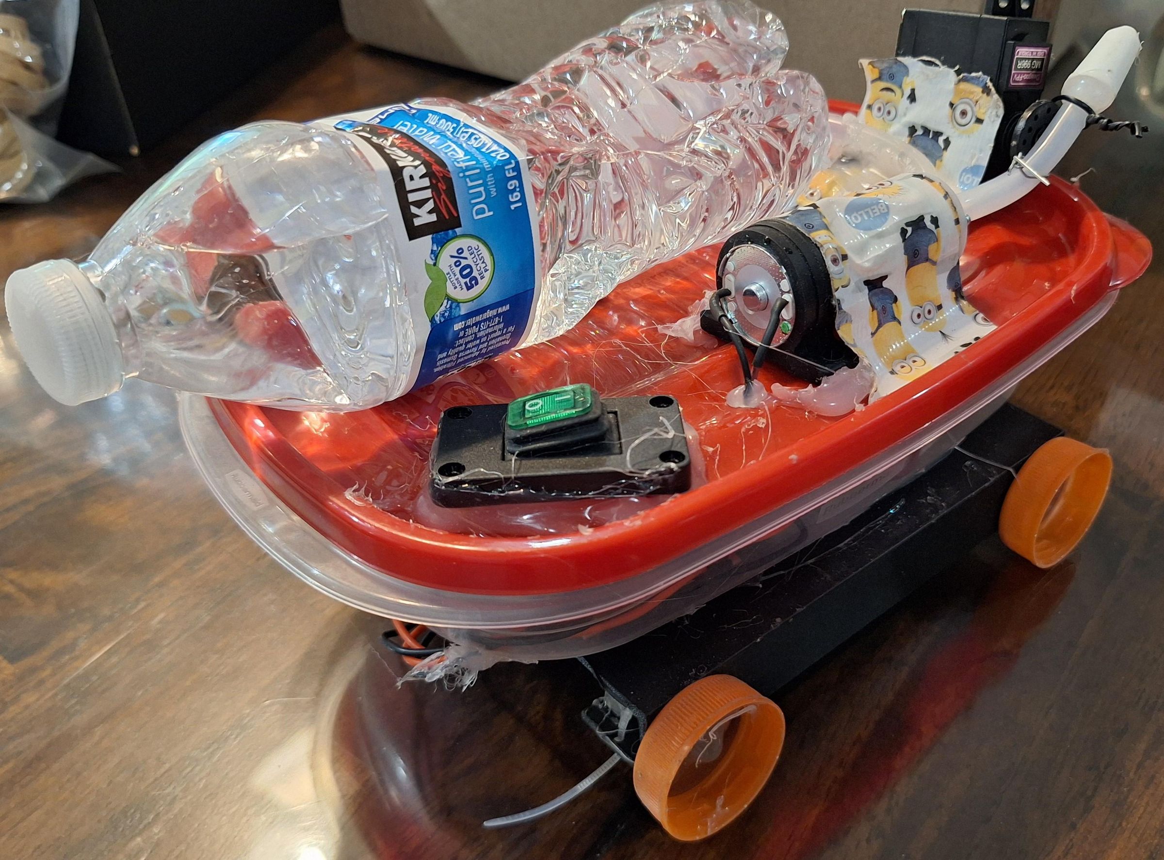
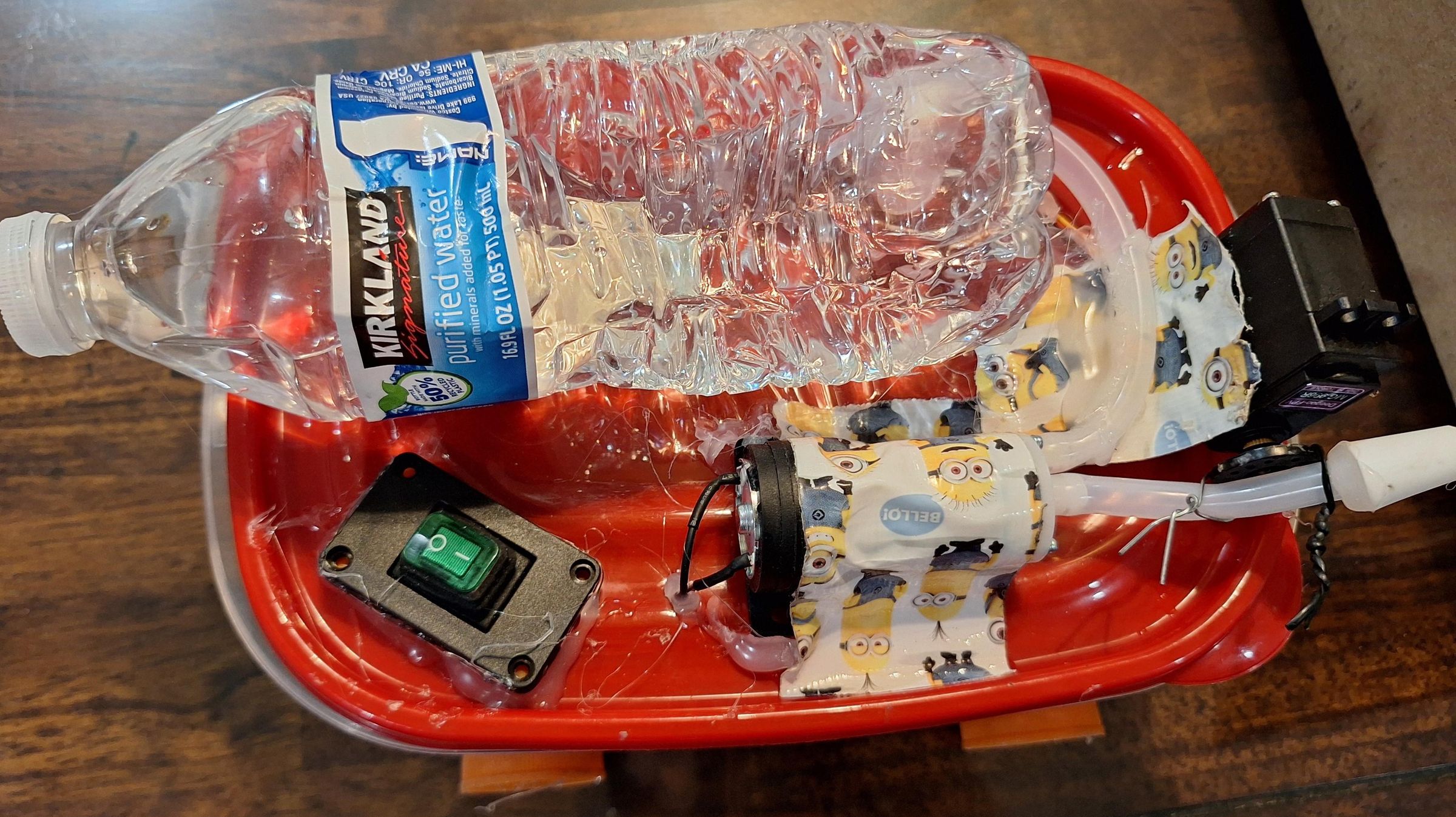
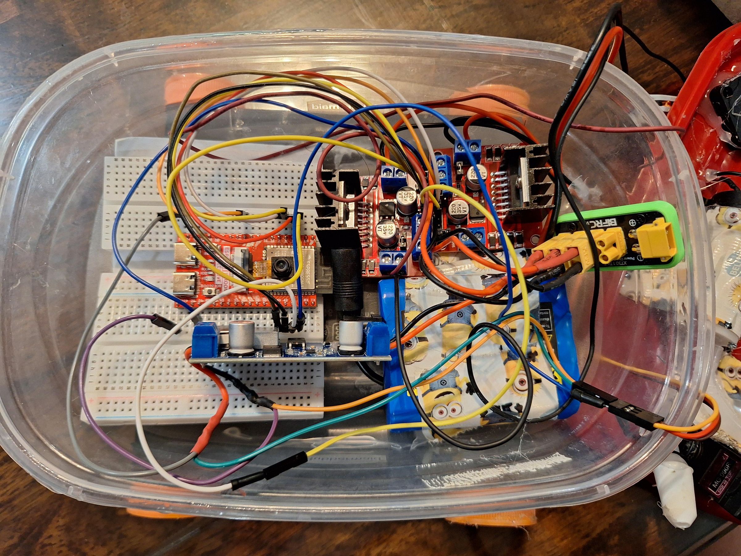
Once you’ve downloaded and modified the ESP32 code, upload the program onto your ESP32 via a USB-C cable. Following this, place the battery, power distribution board, motor drivers, buck converter, and ESP32 inside the waterproof food container. Then, cut a hole for the motors and glue the container onto the 3D-printed body.
Attach the switch, servo, pump, and water bottle onto the container lid, poking holes into the lid to allow the wires to pass through. Fill in these holes with hot glue after inserting the wires to prevent water from leaking in. Then, secure the components with hot glue and duct tape. When you're done, place the lid onto the food container to seal everything up.
Afterwards, cut a hole in the water bottle and connect it to the pump with the water tubes. Glue on or tie the output of the pump to the servo to angle the shot. Finally, attach the drive motors to the robot body and put on the wheels.
Spray Your Friends + Conclusion
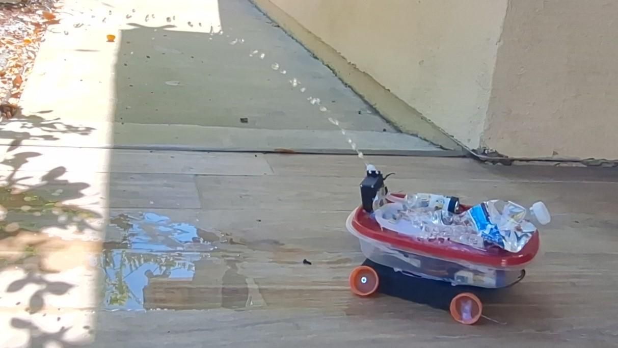
Fill up the water bottle, charge the battery, and send out the water gun robot to spray your friends (or plants)! A couple of these robots can take over any backyard battlefield.
The end of this Instructable is not the end of this project. Try to customize your water gun robot by creating different nozzles and seeing how far it sprays. You can continue to experiment by implementing different drive systems, creating your own programs, or building a fearsome fleet.
One thing this project highlighted was the versatility of engineering. When the 3D printer broke, I thought that this project might have been over. However, through some quick thinking, I was able to find random objects around my house that did the job. As creators, we can find ways to make things work. Nothing can stop us from cooling down our friends and family (with water jets) on a hot summer day.