DIY Sleep Lamp: Track Your Sleep and Vitals
by techiesms in Circuits > Sensors
136 Views, 0 Favorites, 0 Comments
DIY Sleep Lamp: Track Your Sleep and Vitals
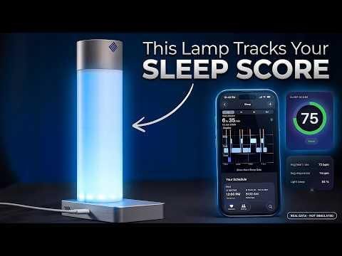
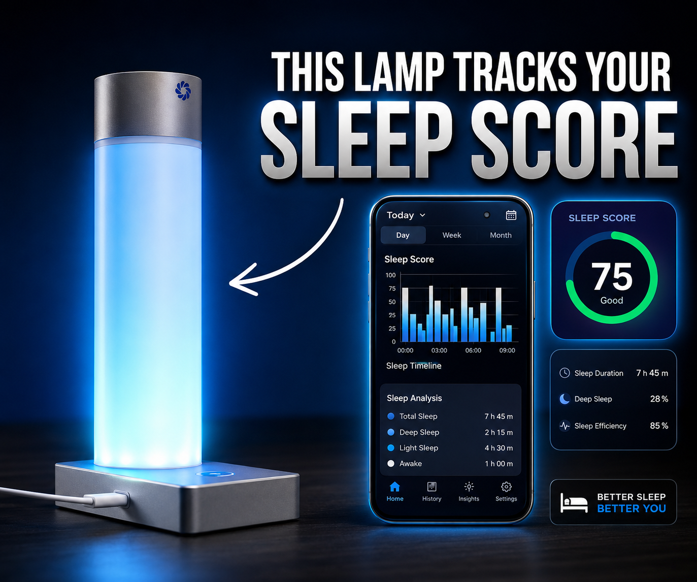
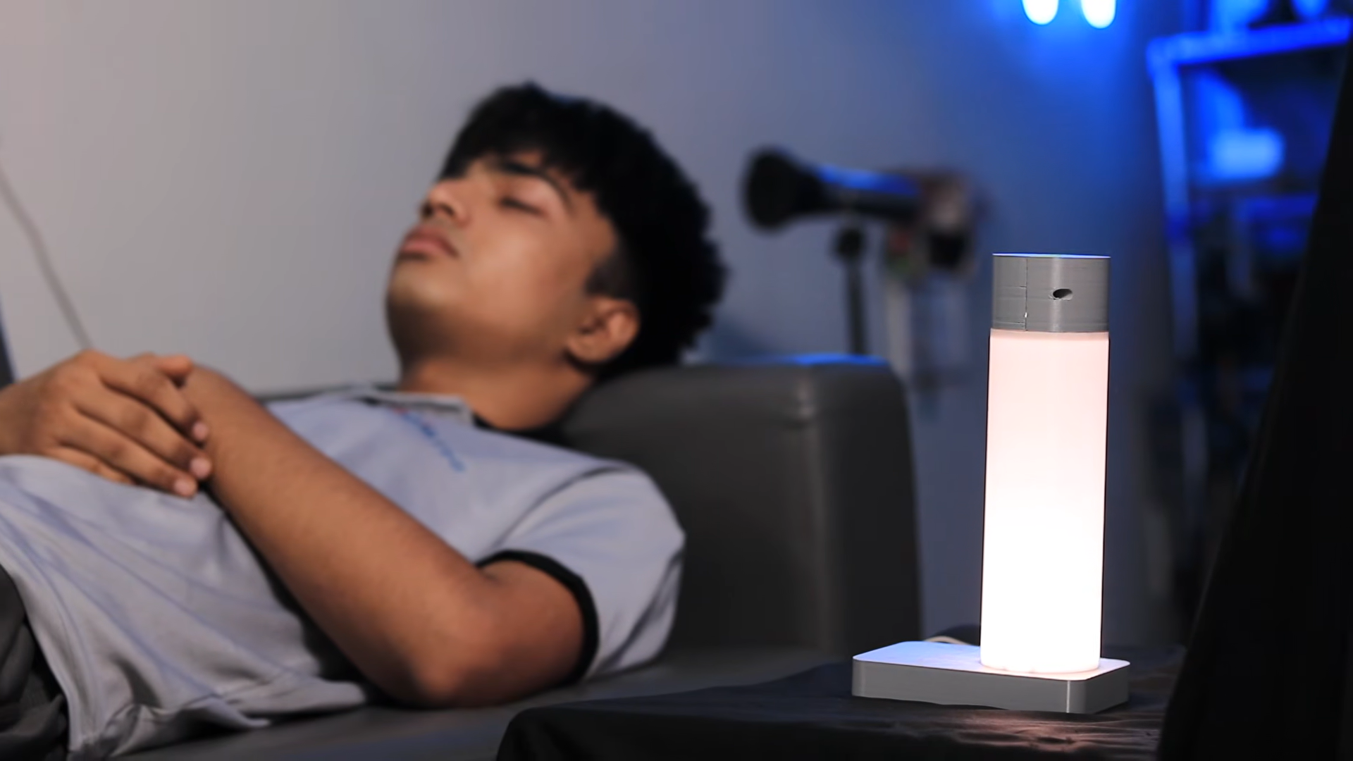
In this project, you will learn how to build your own DIY Contactless Smart Sleep-Tracking Lamp using the ESP32-S3 microcontroller and a mmWave radar sensor. This device sits on your bedside table and measures your complete sleep score, including heart rate, respiration rate, deep/light sleep cycles, and turnovers without touching your body.
Unlike traditional smartwatches and rings that require overnight wearing and constant charging, this lamp operates entirely contactless from up to 1.5 meters away while doubling as a soft, touch-controlled NeoPixel night light.
Supplies
Main Electronics:
- ESP32-S3 (N16R8) — Main microcontroller with Wi-Fi and Bluetooth capabilities
- DFRobot mmWave Radar Sensor (SEN0623 / C1001) — For the true Contactless Tracking
- NeoPixel LED Ring — Bedside night light and heartbeat animation display
- TTP223 Touch Sensor — Capacitive interface for NeoPixel brightness control
- DHT11 Sensor — Ambient room temperature monitoring
- CH340 Programmer IC — USB-to-serial interface for flashing firmware
- USB Type-C Port — 5V power input and programming interface
PCB & Assembly:
- Custom PCB (manufactured via NextPCB)
- GST Connectors — For modular sensor wiring
- Solder paste & stainless steel stencil
- SMD components & RX/TX status LEDs
- 5V-to-3.3V Voltage Regulator
- Hand soldering tools & reflow hot plate
Enclosure & Hardware:
- 3D Printed Enclosure Files - Main body, base, back panel, and 360° swiveling sensor head
- Mounting screws and standoffs
- Double-sided mounting tape
Why We Chose the MmWave Radar Sensor
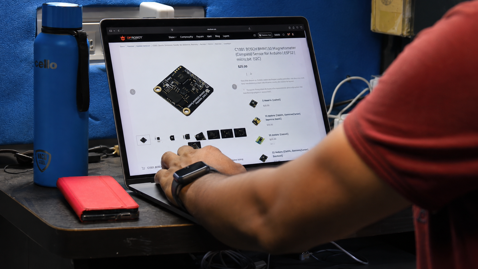
When building a sleep tracker, picking the right sensor comes down to choosing between four main approaches: wearables, cameras, piezoelectric bed pads, and radar. Here is why the DFRobot mmWave radar sensor was the clear winner for this project:
1. True Contactless Tracking (No Wearables Needed):
- Smartwatches, rings, and chest straps give great data, but they break down in real life—you forget to wear them, or they need charging overnight. This 60GHz radar operates from up to 1.5 meters away sitting on a nightstand, requiring zero physical contact.
2. Penetrates Blankets and Clothes:
- Unlike optical sensors or infrared cameras that require direct line-of-sight to skin, mmWave millimeter waves pass right through thick winter blankets, pajamas, and heavy duvets to detect the tiny chest micro-movements caused by breathing and heartbeats.
3. Complete Bedroom Privacy:
- Placing a camera in a bedroom is a major privacy concern for most people. The mmWave sensor collects spatial radar reflection data—meaning it tracks movement, respiration, and heart rate without ever recording or capturing actual images of your bed.
4. Sub-Millimeter Movement Detection:
- Standard PIR motion sensors (like the ones in security lights) can only tell if a whole body is moving. The 60GHz C1001 mmWave radar is sensitive enough to measure tiny chest displacements, allowing it to isolate heartbeats (~1 Hz) and breathing (~0.25 Hz) from simple body turns.
Circuit Design and PCB Assembly

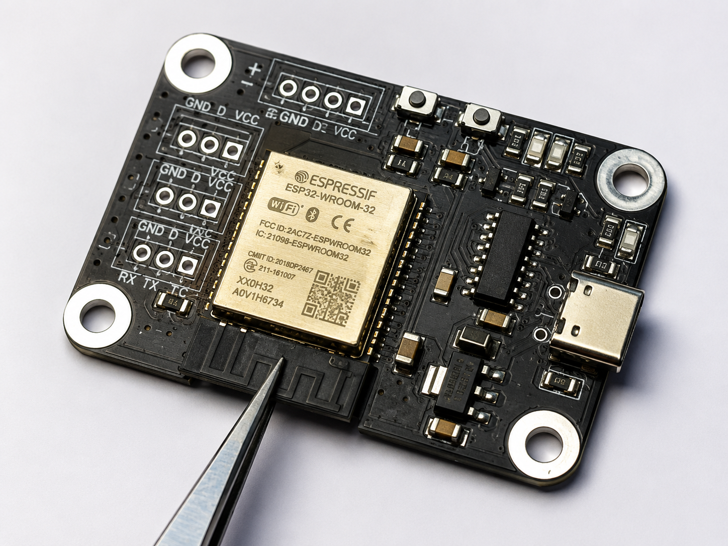
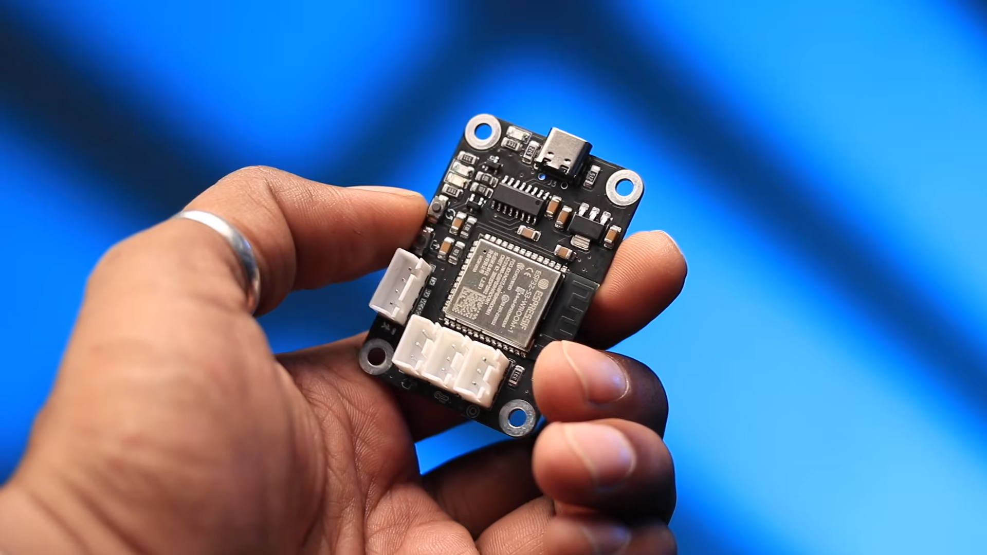
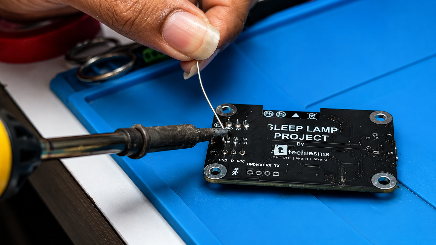
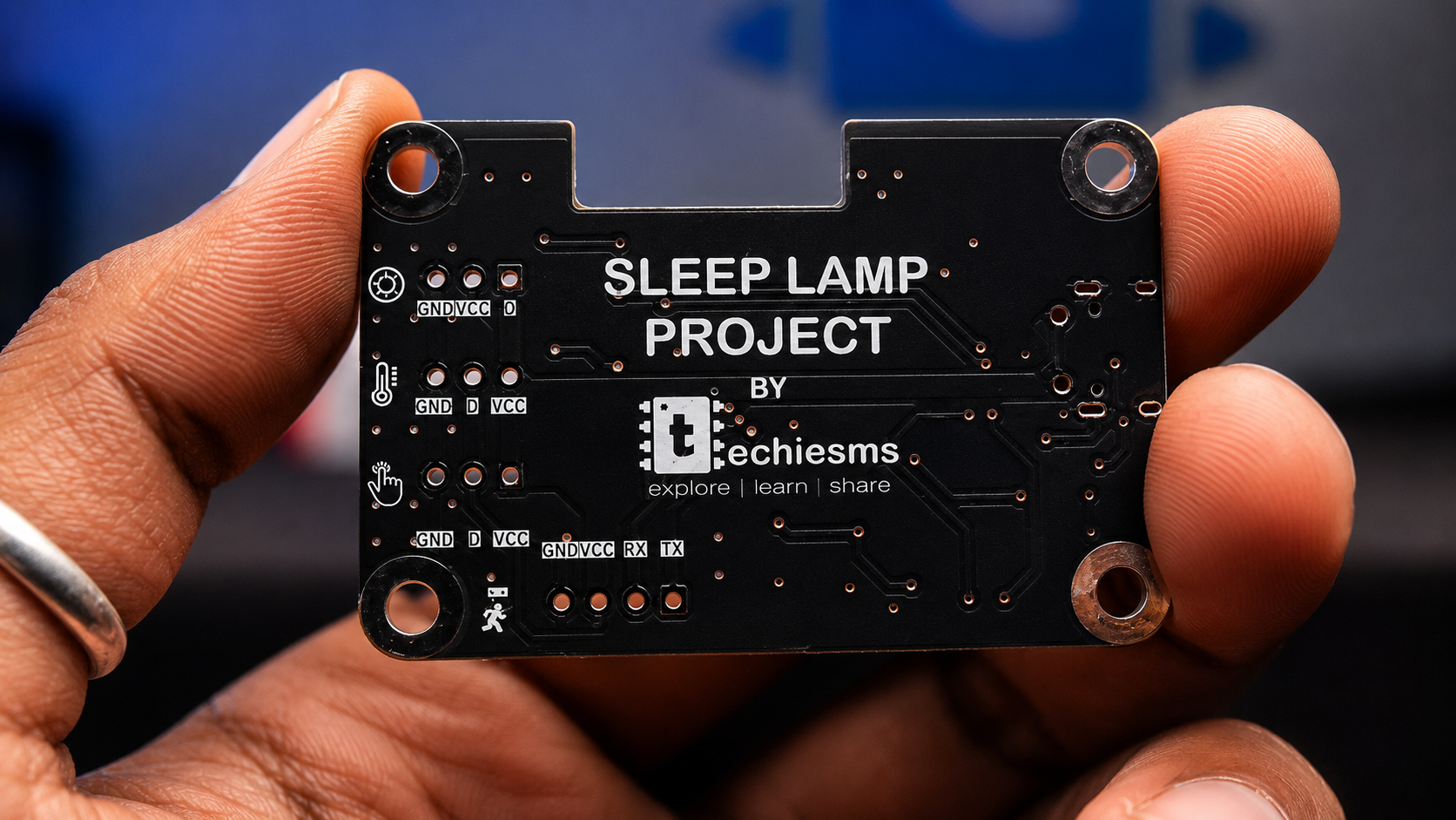
At its core, the system is built around the ESP32-S3 (N16R8) microcontroller. Rather than running bare wires across a breadboard, the system uses modular GST connectors routed to individual GPIO pins to make swapping or servicing sensors straightforward:
- CH340 Programmer IC & Type-C Port: Handles power delivery and serial programming. An onboard voltage regulator steps down the 5V USB line to 3.3V for the ESP32 and logic circuits. An RX/TX status LED gives a visual signal during firmware uploads.
- DFRobot mmWave Radar Sensor: Connects via serial/GPIO as the primary physiological tracking input.
- TTP223 Touch Sensor & NeoPixel Ring: The TTP223 acts as a digital input trigger to step through NeoPixel brightness levels and light modes.
- DHT11 Sensor: Connects via a single digital pin to gather ambient bedroom temperature as a secondary sleep metric.
PCB Layout & Assembly:
To transition from a prototype to a polished product, the circuit was routed into a compact PCB layout.
Sponsored by NextPCB:
The custom PCB used in this project was manufactured by NextPCB featuring a matte black finish and a framed stencil for solder paste application. NextPCB provides PCB prototyping, SMT assembly solutions, multilayer manufacturing, and automated DFM (Design for Manufacturing) analysis to ensure reliable PCB production.
Flashing the Firmware
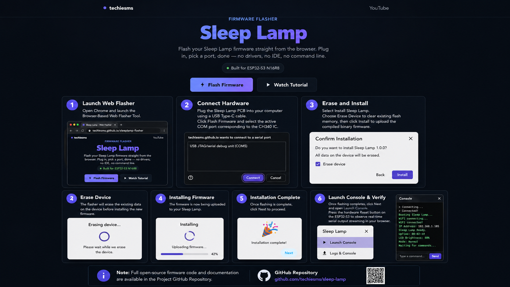
Instead of requiring complex IDE setups, board packages, or manual library installations, the firmware is flashed directly via your browser.
- Launch Web Flasher: Open Chrome and launch the Browser-Based Web Flasher Tool.
- Connect Hardware: Plug the Sleep Lamp PCB into your computer using a USB Type-C cable. Click Flash Firmware and select the active COM port corresponding to the CH340 IC.
- Erase and Install: Select Install Sleep Lamp. Choose Erase Device to clear existing flash memory, then click Install to upload the compiled binary firmware.
- Launch Console & Verify: Once flashing completes, click Next and open Launch Console. Press the hardware Reset button on the ESP32-S3 to observe real-time serial output streaming in your browser.
Note: Full open-source firmware code and documentation are available in the Project GitHub Repository.
Web Dashboard and Calibration Setup
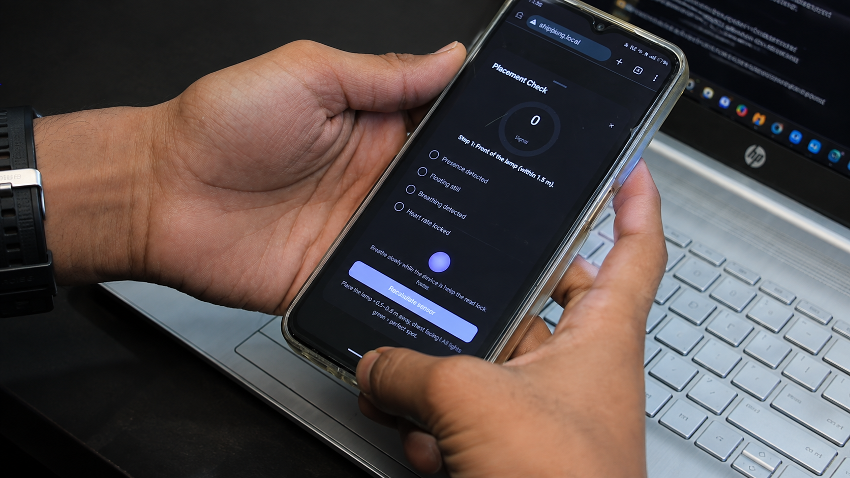
The firmware processes raw high-frequency radar data into actionable sleep metrics and serves a local web dashboard:
- Sleep-Stage Logic: Calculates stage transitions (Awake, Light Sleep, Deep Sleep) derived from heart rate variability and physical movement spikes.
- Ambient Parameters: Displays real-time room temperature data sent from the DHT11 sensor.
- Session Storage: A calendar widget archives historical sleep sessions for easy browsing.
- Heartbeat Pulse Visual: The NeoPixel ring executes a subtle heartbeat animation when the mmWave sensor establishes a reliable target lock, confirming active tracking at a glance.`
Live Sensor Calibration:
Because mmWave sensors require direct chest alignment and operate within a 1.5-meter detection range:
- Place the lamp on your bedside table.
- Access the Calibration Mode page on the web dashboard.
- Adjust the lamp angle until the dashboard and NeoPixel pulse animation confirm a continuous heartbeat and respiration lock on your sleeping position.
3D Printed Enclosure Assembly
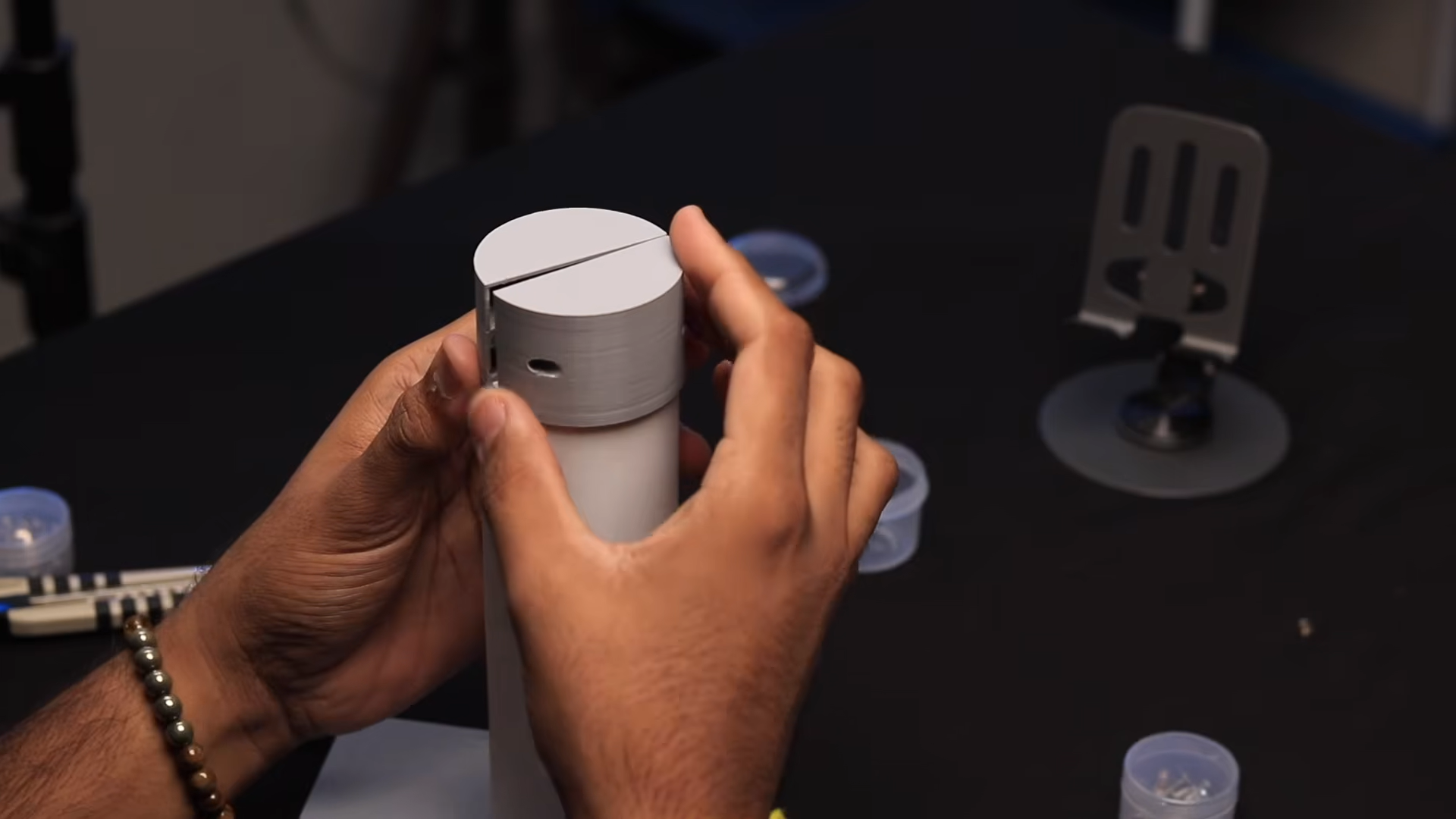
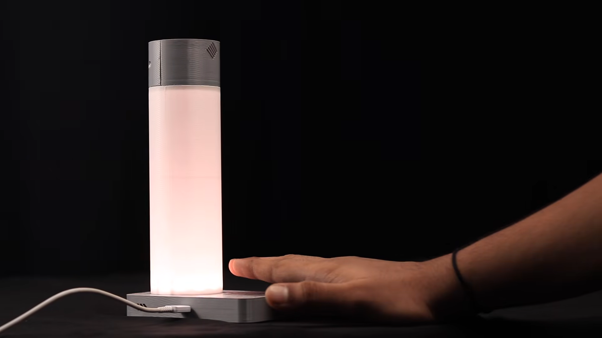
Download the 3D files from the GitHub Repository and assemble the lamp components in the following order:
- Mount Environmental Sensor: Fit the DHT11 sensor into its dedicated cutout in the lower housing wall.
- Secure PCB: Position the main PCB over the internal standoffs and secure it using mounting screws.
- Attach Touch Sensor: Secure the TTP223 capacitive touch pad behind the top housing wall using double-sided tape.
- Wire Connectors: Plug all modular GST wire leads into their matching PCB headers.
- Assemble Swiveling Head: Route the mmWave sensor cable through the swiveling joint, place the sensor into the 360° rotating head shell, and screw the head halves together.
- Mount Lighting Ring: Fit the NeoPixel LED ring into the lower lamp diffusion housing at the base.
- Seal the Enclosure: Fasten the back panel with screws and snap the base plate into position.
Testing and Results
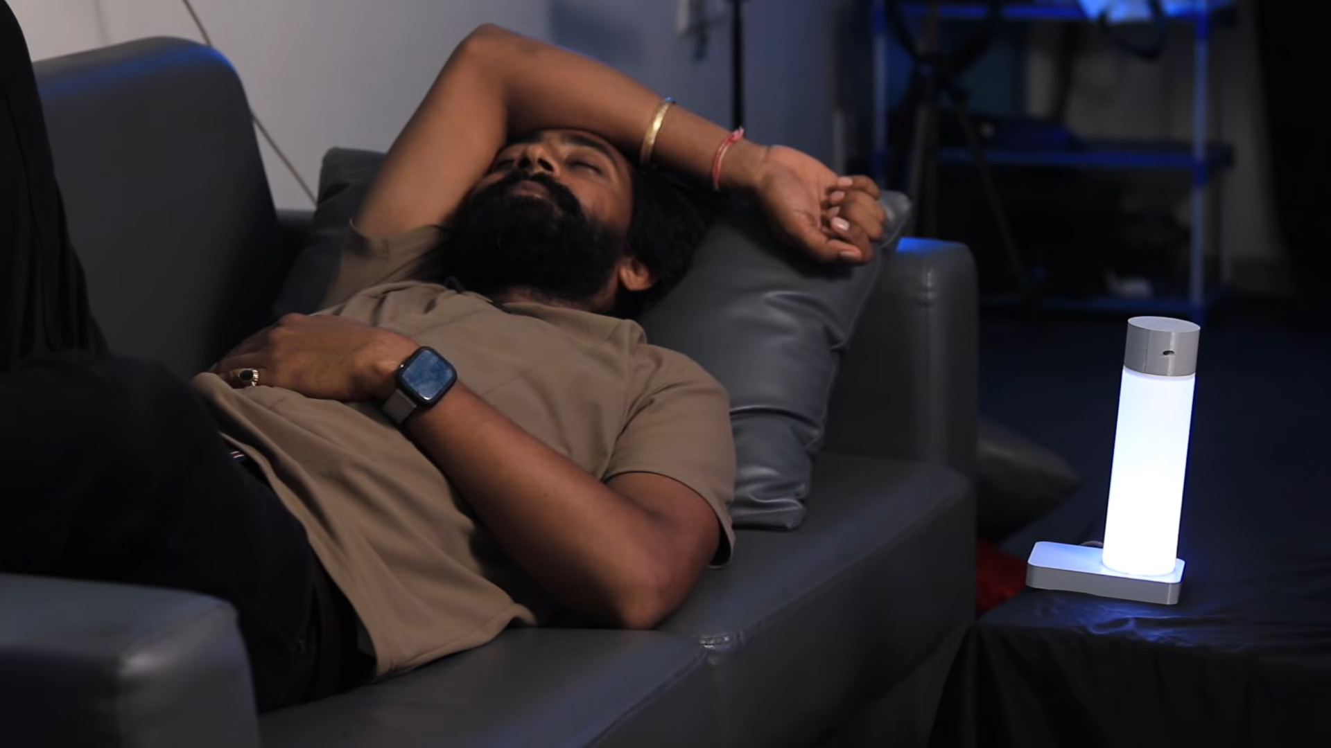
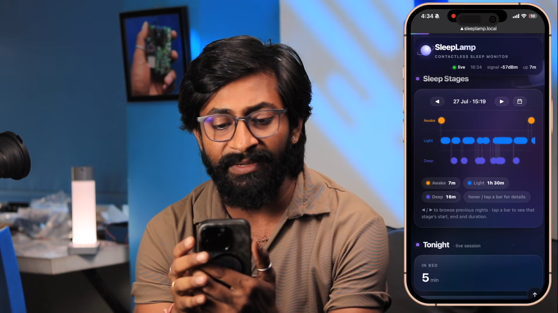
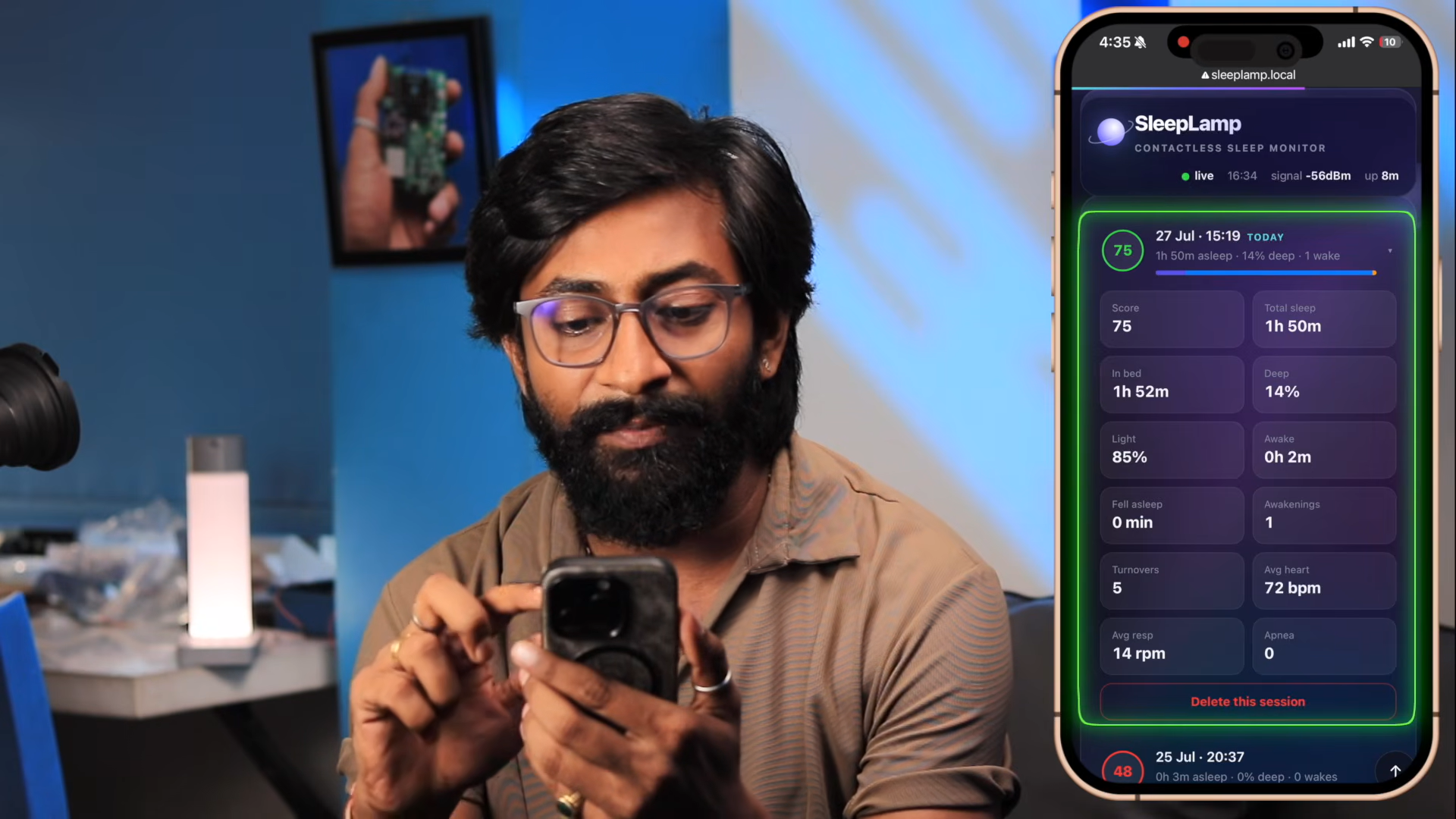
Before setting it up by the bed, I gave the lamp a quick dry run on my desk to make sure the touch controls were working and the radar was picking up movement properly.
For the real test, I took a short afternoon nap on the sofa. I pointed the lamp toward my chest, calibrated it, and let it run. Here’s what the dashboard showed when I woke up:
- Time in bed: 1 hour 52 minutes (112 mins)
- Actual sleep time: 1 hour 50 minutes (110 mins)
- Deep sleep: 14%
- Light sleep: 85%
- Woke up: 1 time
- Turnovers: 5 times
- Average heart rate: 72 bpm
- Average breathing rate: 14 breaths/min
- Overall Sleep Score: 75%
Overall, it tracked through my clothes and blanket without needing any wristbands or rings, which was the whole goal of the build!
Conclusion
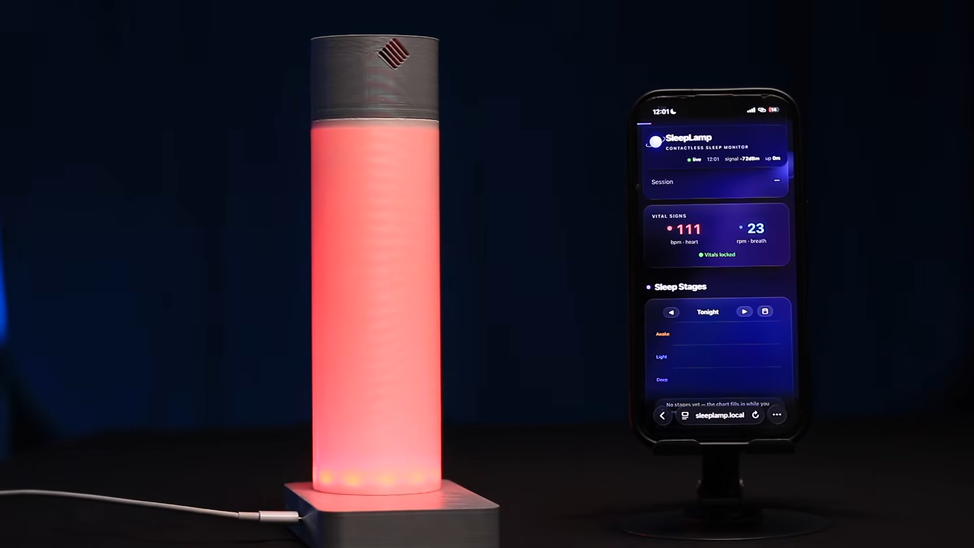
This project successfully demonstrates a fully functional, contactless smart sleep tracker housed inside a bedside lamp. By combining mmWave radar sensing with the ESP32-S3, you can monitor vital sleep metrics—heart rate, respiration, movement, and sleep stages—without wearing smartwatches or rings overnight.
All assets for this project are completely open source....