DIY Spot Like Quadruped Robot (building Log V2)
by steven sturgis in Circuits > Robots
3648 Views, 28 Favorites, 0 Comments
DIY Spot Like Quadruped Robot (building Log V2)


This is a building log with detailed instructions on how to build https://www.instructables.com/DIY-Spot-Like-Quadru...robot dog v2.
Follow Robolab youtube site for more information. https://www.youtube.com/robolab19
This is my first robot and I have some tips to share with beginners like me.
Supplies
12x LX-16A smart servos (3 per leg) https://www.hiwonder.hk/collections/bus-servo/prod...
Serial Bus Servo Controller: https://www.hiwonder.hk/collections/servo-controll... I have not got this to work yet. use debugging board below.
USB Debugging Board https://www.hiwonder.hk/products/hiwonder-ttl-usb-...
Raspberry Pi 4 Model B https://www.amazon.com/gp/product/B07TC2BK1X/ref=p...
CanaKit 3.5A Raspberry Pi 4 Power Supply (USB-C) https://www.amazon.com/CanaKit-Raspberry-Power-Sup...
Samsung (MB-ME32GA/AM) 32GB 95MB/s (U1) microSDHC EVO Select Memory Card with Full-Size
Adapter WHDTS 20A Power Supply Module DC-DC 6V-40V to 1.2V-35V Step Down Buck Converter Adjustable Buck Adapter CVCC Constant Voltage Constant Current Converter LED Driver https://www.amazon.com/Samsung-MicroSDHC-Adapter-M...
Valefod 10 Pack DC to DC High Efficiency Voltage Regulator 3.0-40V to 1.5-35V Buck Converter DIY Power Supply Step Down https://www.amazon.com/gp/product/B076H3XHXP/ref=ppx_yo_dt_b_search_asin_title?ie=UTF8&psc=1
https://www.amazon.com/AmazonBasics-Type-C-USB-Male-Cable/dp/B01GGKYN0A/ref=sr_1_1?crid=15XWS5U537QEA&dchild=1&keywords=usb+to+type-c+cable&qid=1603650739&sprefix=usb+to+type-c+cable%2Caps%2C185&sr=8-1
Noctua fan for raspberry pie cas
Bearings per each leg:
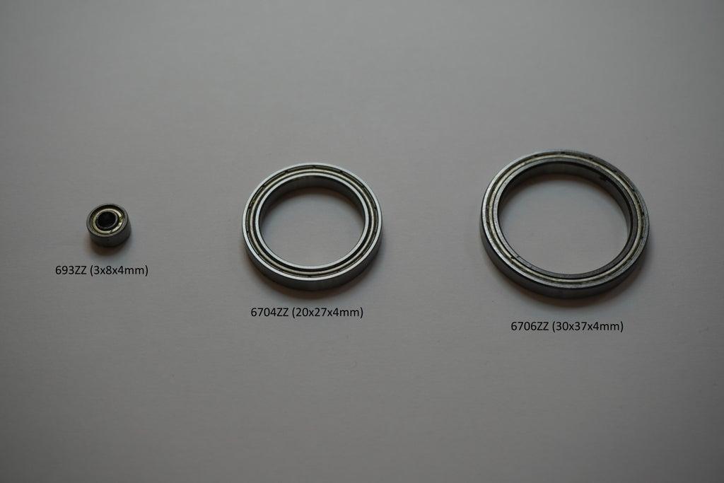
2x 693ZZ (3x8x4mm)
3x 6704ZZ (20x27x4mm)
1x 6705ZZ (25x32x4mm) 4 in all
Bearings per each leg's hip:
2x 693ZZ, 8 in all
2x 6704ZZ 20 in all
Phillips self tapping screws M1.7 x 8mm About 150 pieces
2x M3 x 14mm self tapping screws for leg gears 16 in all
1x M3 x 23mm self tapping screws for hip 4 in all
2x M3 washers per leg, between leg gear and bearings (693ZZ) 12 in all
8 x 3mm x 10mm nuts and bolts. 4 in all
I order a few extra of each screw just in case my count was off.
STL Files for 3D Printing:

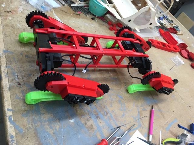
RoboDog v1.0 by robolab19 June 11, 2020 https://www.thingiverse.com/thing:4445119
use these Stl files for printing the body parts only no legs.
Quadruped robot V2.0 by robolab19 July 31, 2020 https://www.thingiverse.com/thing:4557938
use these Stl files for printing the V2 legs.
Raspberry Pi 4B Box (Noctua Fan variable) https://www.prusaprinters.org/prints/4645-raspberr...
Assembly the Lower Leg


When you add the gears to the legs note there are holes in the gears on one side only this is for the bearing caps. Make two sets with the holes face away from each other for right and left legs. Use two 3mm x 18mm screws in each foot to attach gear.
Building the Servo Tray Upper Leg
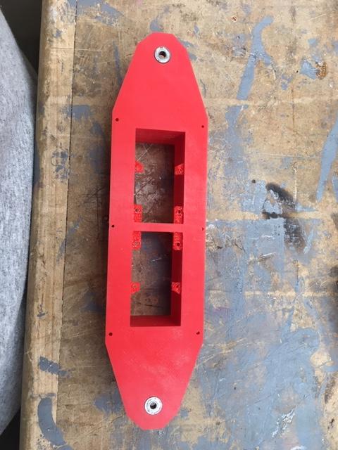


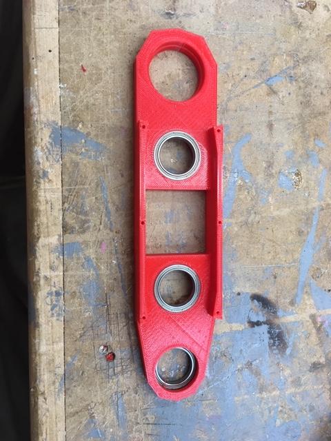




.JPG)


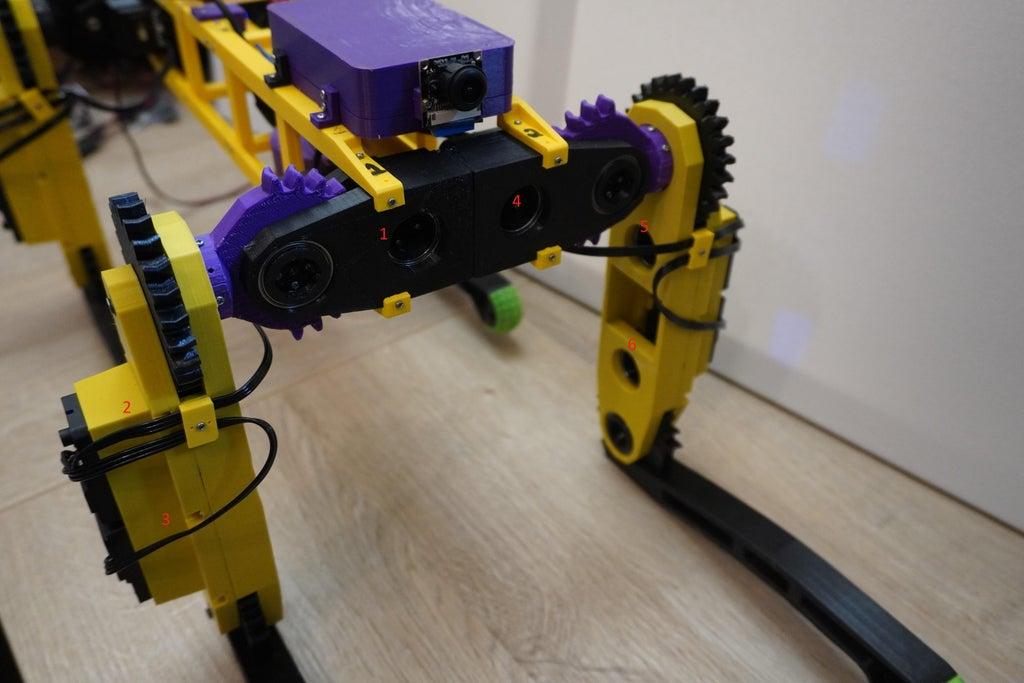

Use two 693ZZ (3x8x4mm) bearings in the upper servo case one at each end and tap them in from the inside
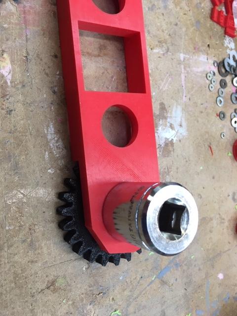
To set the bearings in the servo tray I used a socket of the right size to tap evenly on them.
In the two center holes of the lower servo case set in the two 6704ZZ (20x27x4mm) bearings. The center two bearings are set from the outside.
Next set the 6705ZZ (25x32x4mm) bearing on the lower shoulder gear and then set it in the lower servo case. The end bearing is set from the inside.
Now set the foot gear in position. Place a cap in the middle of the bearing. Add four 1.7mm x 8mm screws thought the holes in the cap while aligning to the existing holes in the gear. There are left and right legs.
Pre set servos to the middle point and assign ID numbers to the servos. https://www.instructables.com/How-to-Configure-and-Use-Smart-Servos-LewanSoul-LX/
Attach the two round servo horns to the servos gears with four 1.7mm x 8mm screws.
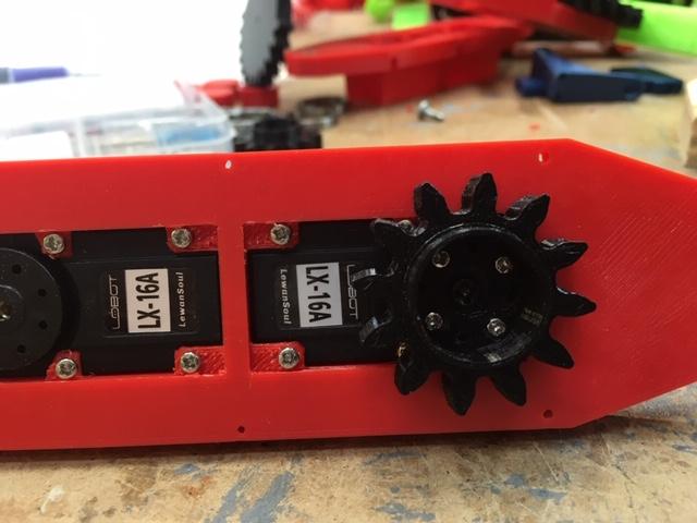
Next place the two servos in the upper servo case and push them down to the tabs. Screw in place with provided screws through the four tabs. Make note of the servo ID numbers they have to match the placements in the photo.
Add two servo horns with gear in to the center holes through the two 6704ZZ (20x27x4mm) bearings of the lower servo case.
Aligning the servo horns with the leg gear at a 90* angle to the lower servo case.
Place the upper servo case on the lower servo case. Rotate the servo gears to line up with servo teeth. Try to move them as little as posable so you don't lose your alignment of 90* on the leg. Screw the top in place with 1.7mm x 8mm screws.
Add a 3mm washer in between the foot gear and the 693ZZ (3x8x4mm) bearing. Secure it with a 3m x 18mm screw through the bearing and into the foot gears center hole. Adjust the tension of the screw so the leg moves freely.
Screw servo horns to servos with provided screws.
*When I did the tuneup gcode the alignment was off a lot on the shoulder. I have not figured out what the best angle is. I would skip this for now and attach when you run the test gcode. When it is in the proper tune up position attach the shoulder gear on the shaft.
Next make sure the bearings and gears are set in all the way.
*(Now place the upper shoulder gear on the shaft of lower servo gear.)
*(Aligning the shoulder gear at a ?* angle to the servo case.)
*(Drill small holes around the upper shoulder gear at the marked points and screw with eight 1.7mm x 8mm screws.)
Add 3mm washer between the bearing and upper servo case. Add screw through bearing into the shoulder gear with 3mm x 23mm screw.
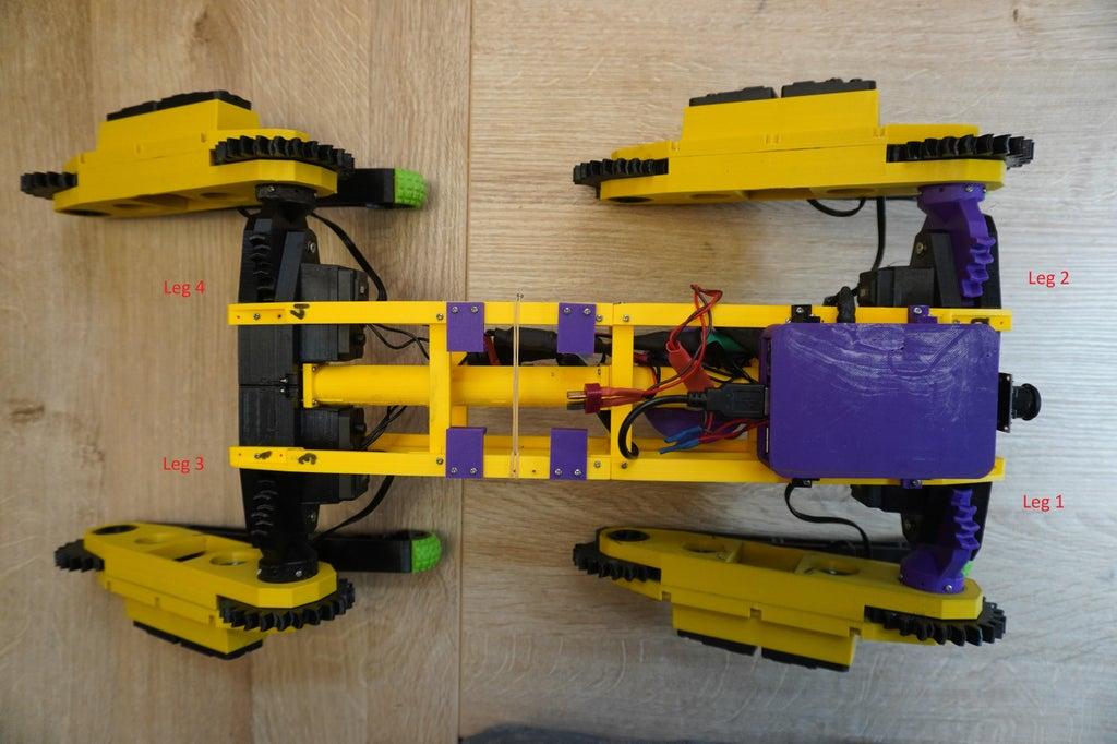
Repeat for the other three legs. Make two left and two right to match the photo orientation.
Building the Shoulder Trays
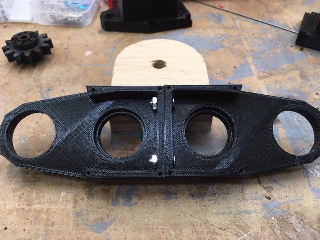

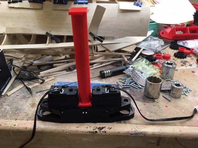
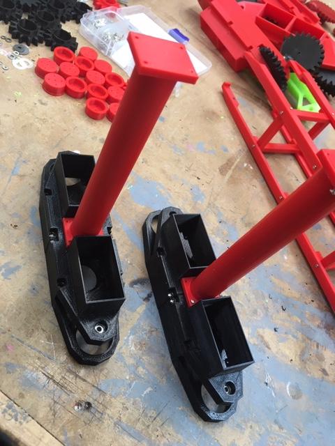
Take the two shoulder bottom cases and bolt them to each other with 3mm x 10mm nuts and bolts.
Use two 693ZZ (3x8x4mm) bearings in the upper servo trays one at each end and tap them in from the inside
Set two 693ZZ bearings, and two 6704ZZ bearings in the lower shoulder case. (as you did in the legs instructions.)
Add two servos to the upper servo cases (as you did in the legs instructions.)
Set the servo horns with gears in to the two center holes through the center bearings.
Screw servo horns to servos with provided screws.
Add the upper cases to the lower case and use 1.7mm x 8mm screws to attach.
Set the center beam on the shoulder cases and drill four holes into the shoulder upper case. Use four 1.7mm x 8mm screws to screw in place.
Building the Body
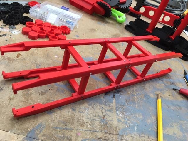
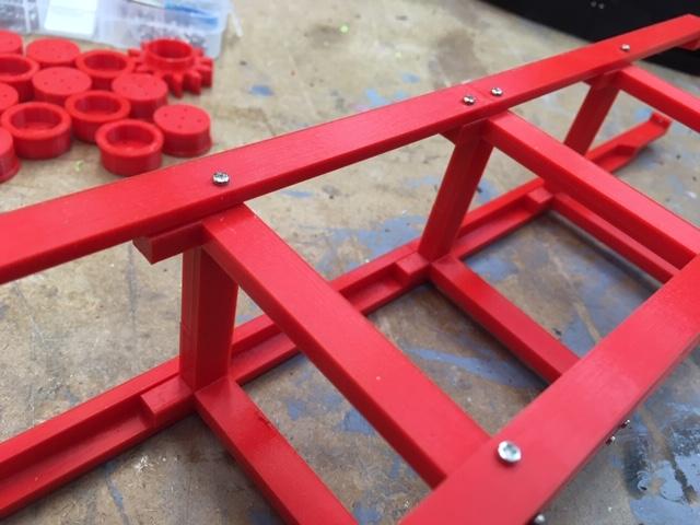

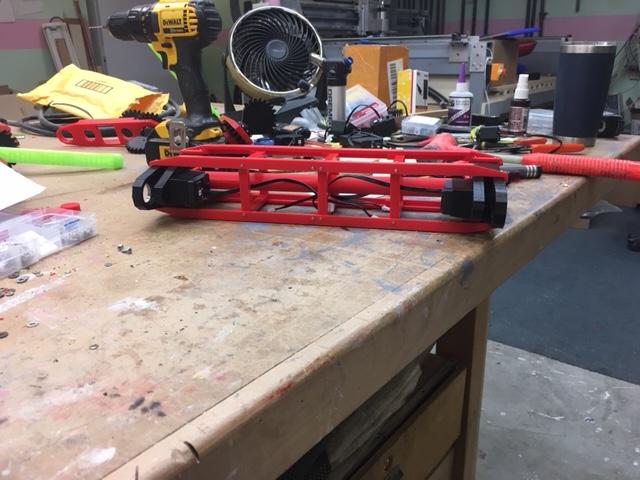
Set the three centers frames in the same direction.
Screw the body rails to the center fames. Using 1.7mm x 8mm screws
Set the shoulder cases in place at each end. servos face in.
Screw center beam ends to each other Using 1.7mm x 8mm screws
Align the tabs to the square edges of the shoulder case and drill holes, using holes in frame rails as guides. Attach Using 1.7mm x 8mm screws
Adding the Legs to Body.
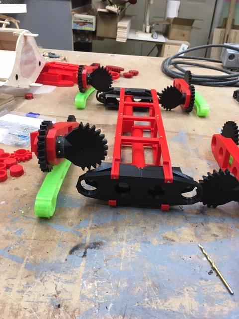
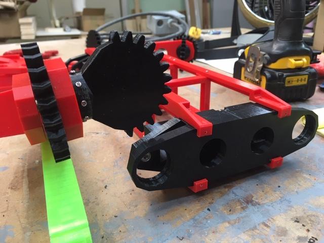

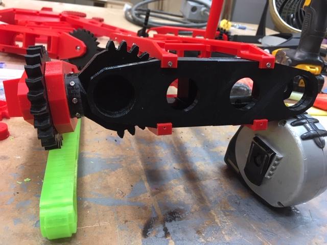
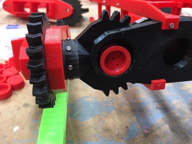
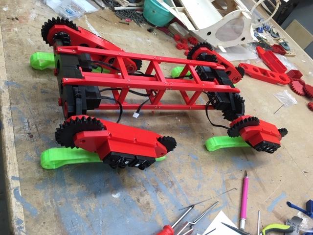
Set out all four legs in there correct positions to see if they all work.
Place the shoulder gear in place while aligning the leg square to the body.
Add 3mm washer between bearing and lower shoulder case. Screw in place with 3mm x 18mm screws through bearings from the back.
Place a cap in the front bearing and drill holes for four 1.7mm x 8mm screws. Screw in place
Repeat four all four legs.
Plug in the servo wires making a chain one to the other.
Run last wire in chain to center of frame.
Add servo wire keepers to legs to hold in place.
Adding the Electronics to Frame
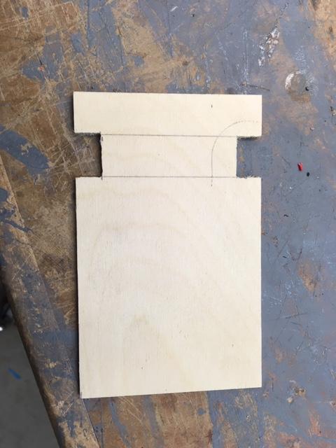

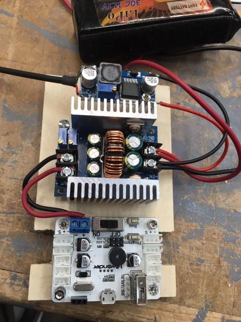

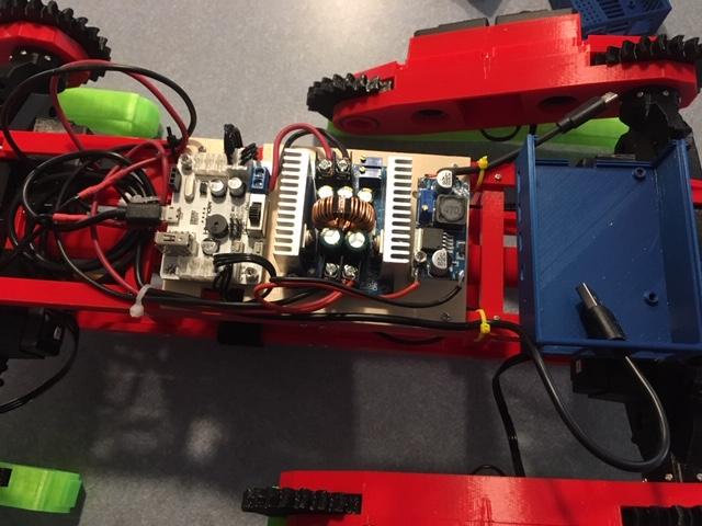
I've cut a piece of 1/8" plywood to make a platform to attach the electronics. The slots are for allowing the servo cables to come from the center of the frame.
I used old standoffs from my computer to get the boards off the plywood.
Make up a set of 14ga wires (red,black) with your batteries connector. I used xt 60 for mine. I added a switch to turn it on and off. I used a 12v lipo battery for my test.
Make up a set of 14ga wires (red,black) for the raspberry pi c-type connector. I used a usb to type-c adapter cable and cut off the large usb end. peel the wires back and use only the red and black wires to the 5v converter.
Attach the wires from the battery to the 20a converters input, at the same point also add a set of wires from the 20a converter input to the 5v converter input. Use the usb type c at the output of the 5v converter. set the volts to 5v for the Pi power needs.
I used the 20A converter to power the servo board from Hiwonder. I used 14ga wire from the converters output to the servo boards inputs. Measure the volts with a volt meter at the output and adjust the volts with the small screw at the outside blue box. set it to 8.4 volts.
use the suppled wire from Hiwonder from the Pi USB to the servo board.
Setting Up the Raspberry Pi With Ubuntu and Ros
I used an image from here https://github.com/RoboLabHub/Tips/tree/master/RoboDog_image with raspberry pi image software https://ubuntu.com/tutorials/how-to-install-ubuntu-on-your-raspberry-pi#1-overview to install them to sd card. Thanks to Robolab19 for the image.
Tune Up and Testing
Plug in the batteries and USB cable. They need to be on for the Pi to see the debug board. I ran the rosrun robodog_v2_hw command and it set its self to the first tune position. I than had to adjust the offsets in the robothw.cpp file code to square the legs. I decided to set all the offsets to 0 and recompile the code. Then I set my own offsets. I did this because the offsets that are in the code are for Robolab19 robot. Make sure the robot is suspended some how because the reset will move the servos alot. Some are in the negative range. You have to save the file and recompile (catkin_make) every time you make a change to the offsets. Then comment the first Ctrl line and uncomment the second Ctrl line (second tune position) and set the offsets again to square the legs. Then comment the second Ctrl line and uncomment the test gcode line. The robot will go through some set commands and then stop. You can make a new line by copying the last test gcode line and replacing the end with some of the other gcodes in the github files. I like the ik_demo.gcode the best. It will go through a lot of the capabilities of the robot. I pared the PS4 controller with the bluetooth of the Pi4.
That's as far as i've got to at this point. I can't get the robot to move with the remote. I just don't know how, remember i'm a beginner. I hope some one can help.