DIY Temperature Controller Using KYT84 & TRIAC
by LongTechnical in Circuits > Electronics
304 Views, 1 Favorites, 0 Comments
DIY Temperature Controller Using KYT84 & TRIAC

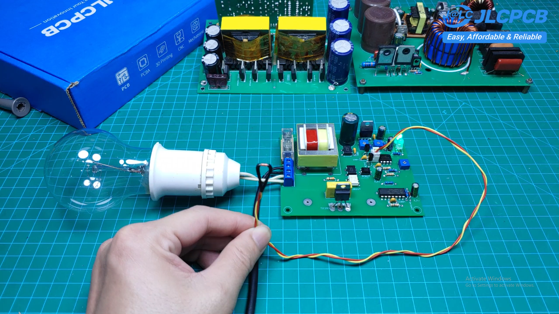
In this project, I built a simple and practical AC temperature controller using the KYT84 temperature sensor.
The circuit is designed to control heating devices such as an electric iron, hot plate, food warmer, or other AC heating elements. It uses temperature feedback to automatically control the heater and maintain the desired temperature. The PCB from JLCPCB
The circuit also provides 0–100 percent power control, making it possible to adjust the heating power according to different applications.
The main components used in this project are the KYT84 temperature sensor, LM358 op-amp, CD4093, MOC3021 optocoupler, and TRIAC.
Supplies
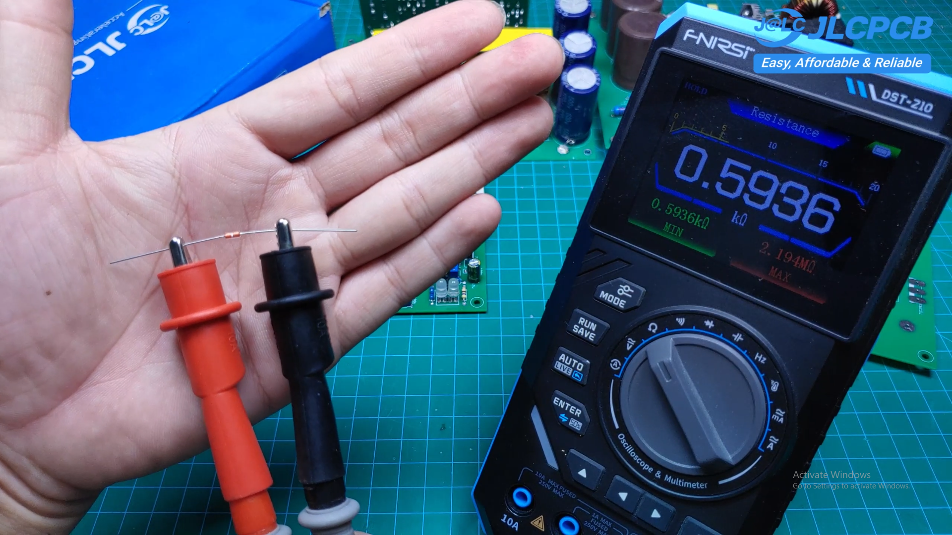
KYT84 Temperature Sensor
LM358 Dual Op-Amp
CD4093 CMOS Schmitt Trigger IC
MOC3021 Optocoupler
PC817 Optocoupler
TRIAC
Resistors
Capacitors
Diodes
Transistors
Potentiometers
5V Voltage Regulator
Bridge Rectifier
Fuse and Fuse Holder
Screw Terminal Blocks
PCB Board
Connecting Wires
AC Power Cable
Electric Iron for Testing
Light Bulb for Testing
Multimeter
Oscilloscope
Soldering Iron
Solder Wire
How It Works
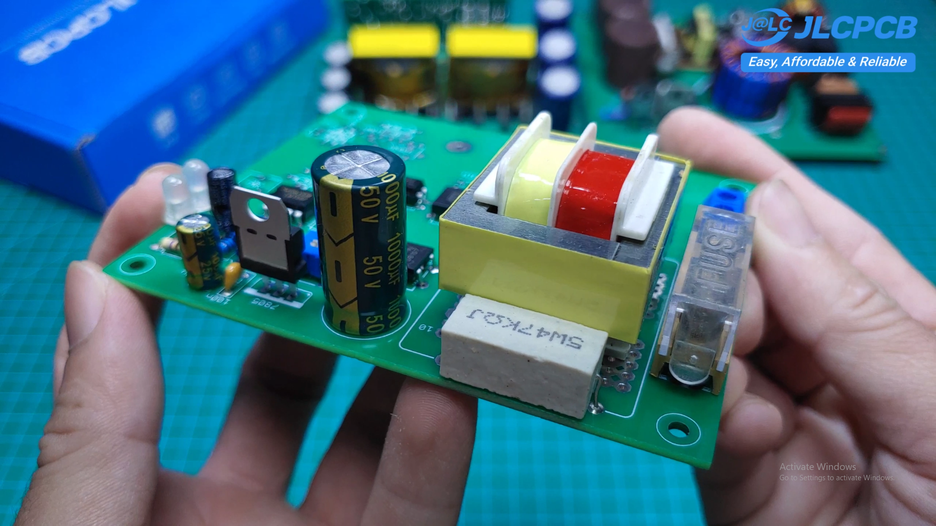
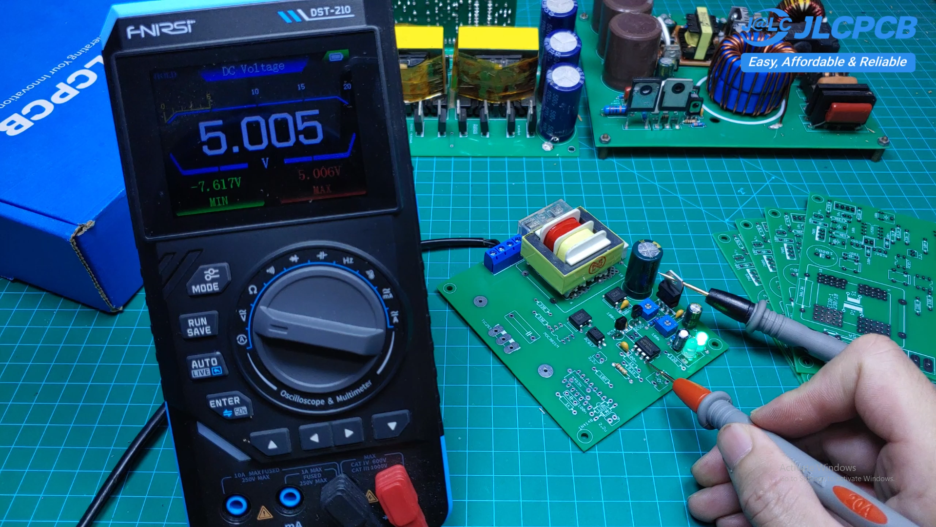
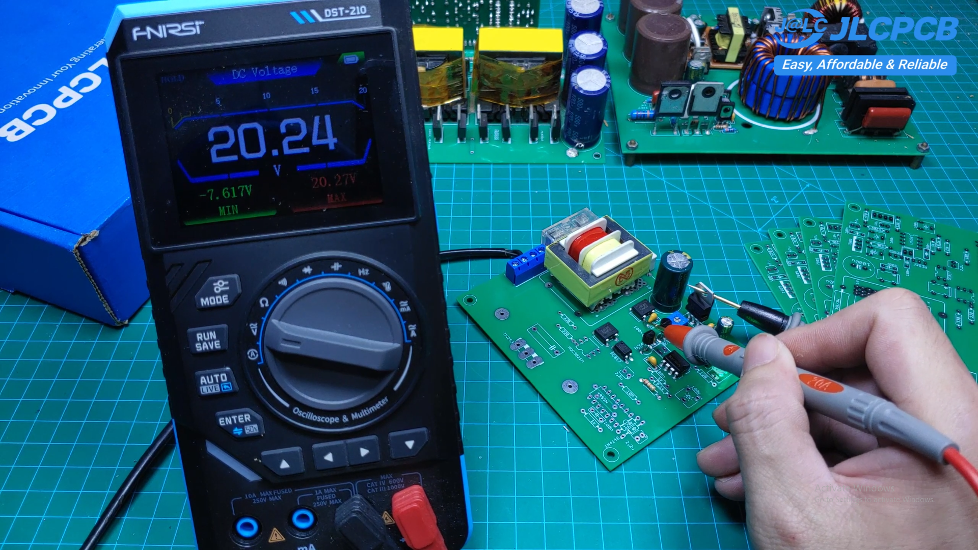
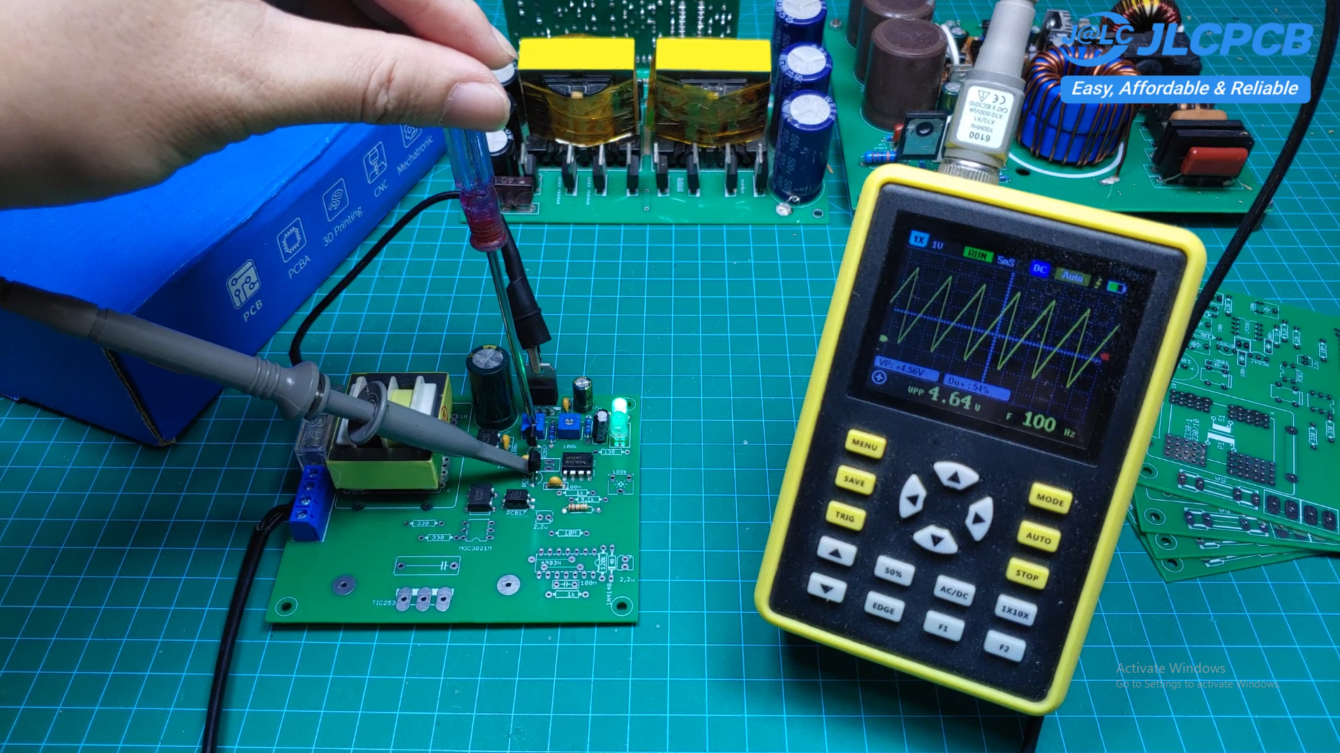
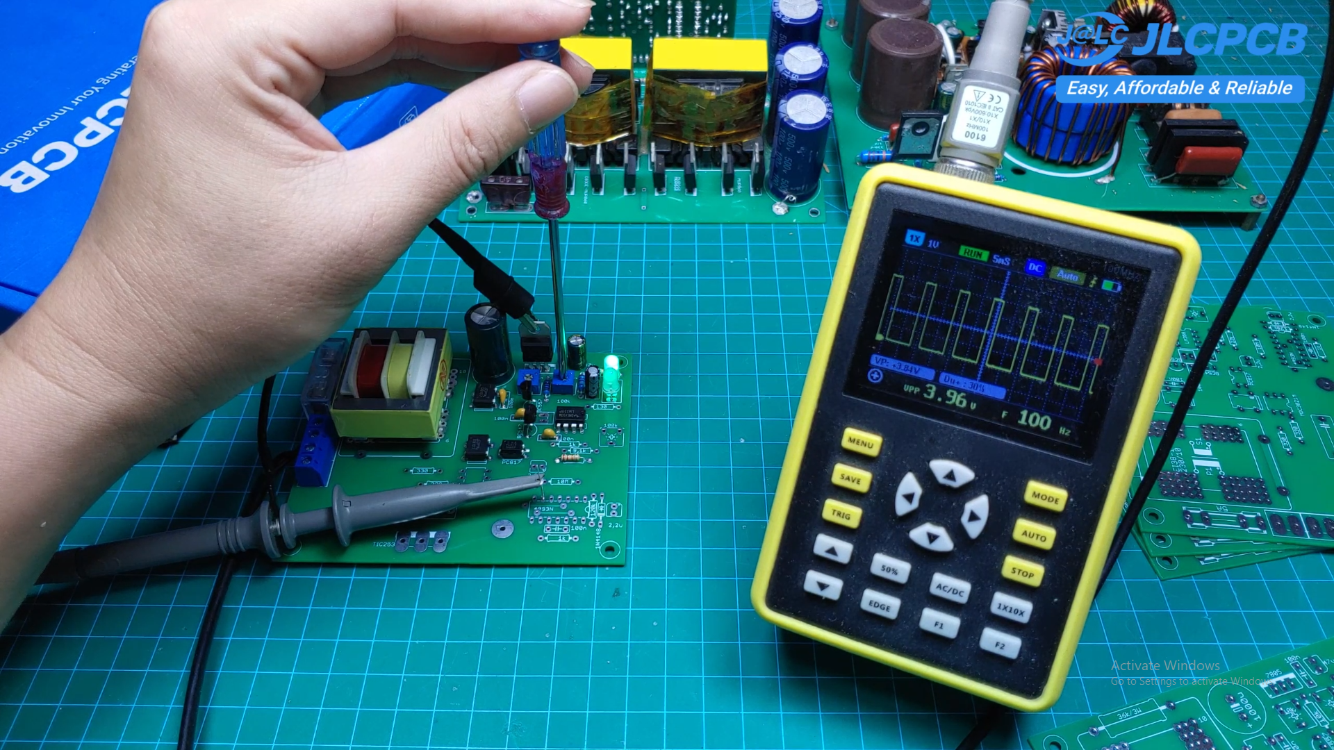
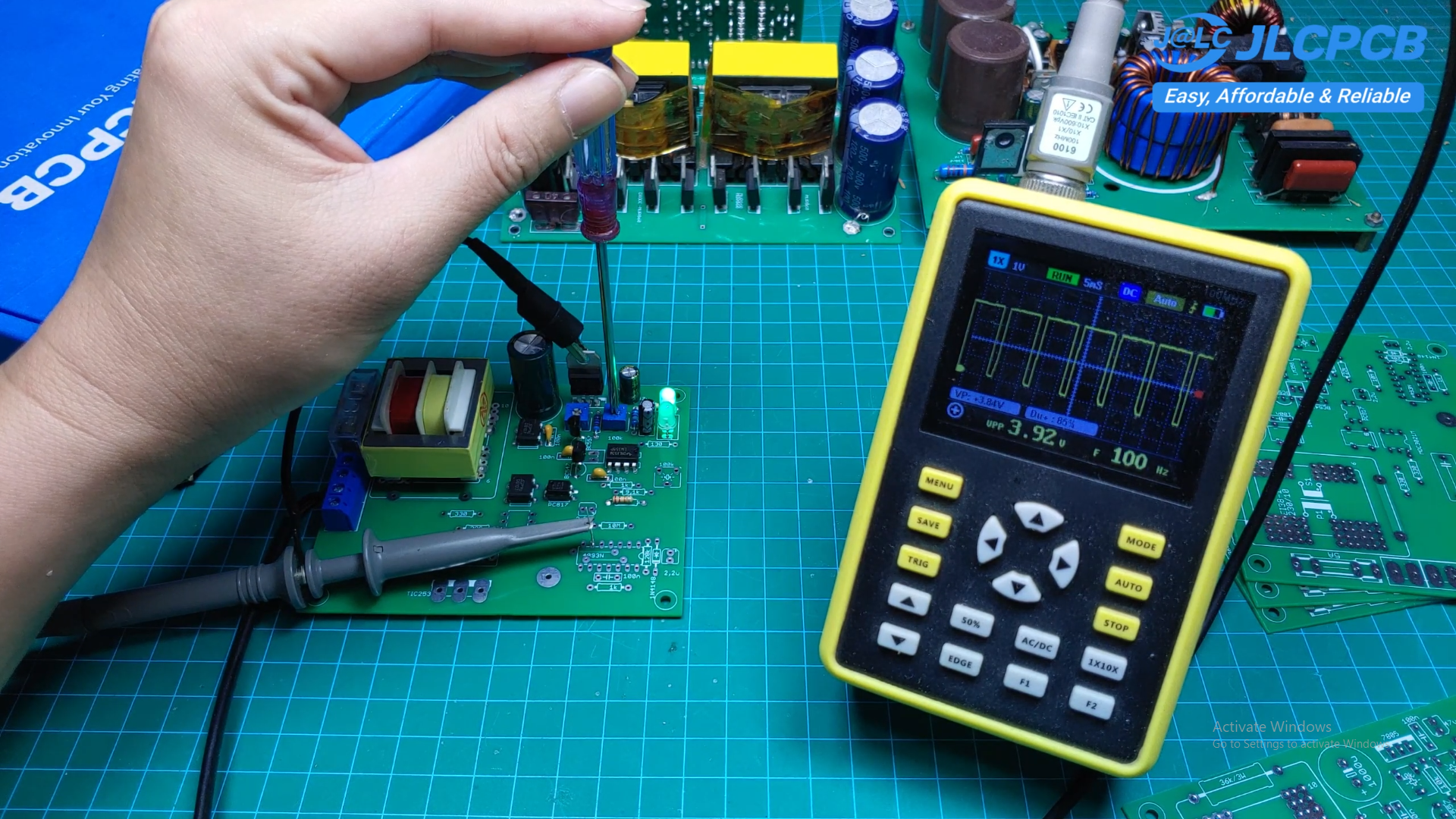
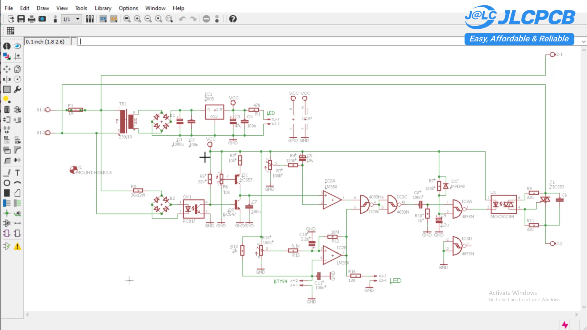
The circuit is divided into several main sections:
- 5 volt power supply
- AC zero-cross detection
- Duty-cycle control
- KYT84 temperature sensing
- LM358 comparator
- CD4093 pulse control
- MOC3021 optocoupler
- TRIAC heater control
The AC input is monitored by the zero-cross detection circuit using a PC817 optocoupler.
After rectification, the signal has a frequency of 100 hertz and is processed by the comparator section.
The LM358 processes the temperature feedback from the KYT84 sensor. The CD4093 then generates the control pulses used to drive the MOC3021 and TRIAC.
By changing the duty cycle, the output power can be adjusted from 0 to 100 percent.
KYT84 Temperature Sensor
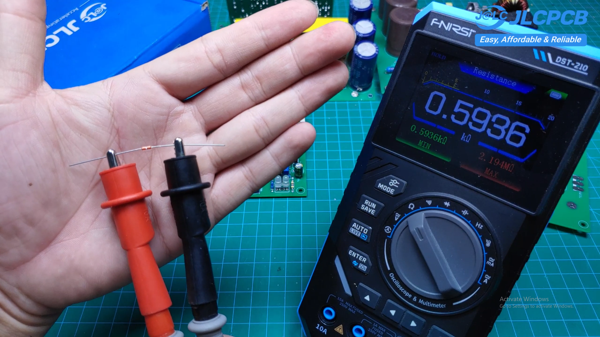
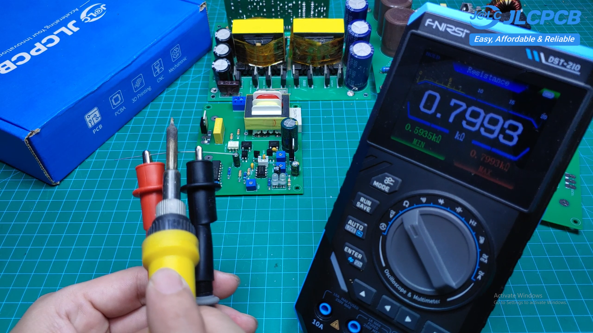
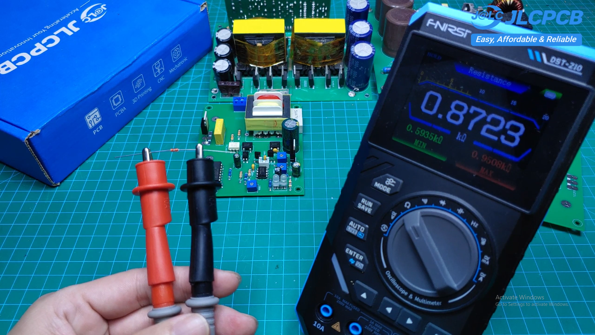
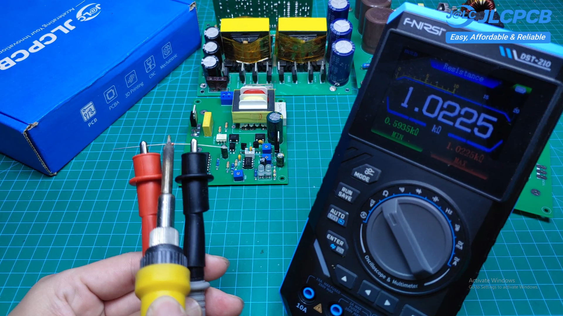
The KYT84 is used as the temperature sensing element in this project.
Its resistance changes according to temperature. When the sensor is heated, its resistance increases. When the temperature decreases, the resistance also decreases.
This resistance change is converted into a voltage signal and processed by the LM358.
The circuit compares the measured temperature with the preset temperature and automatically controls the heater.
Temperature Control
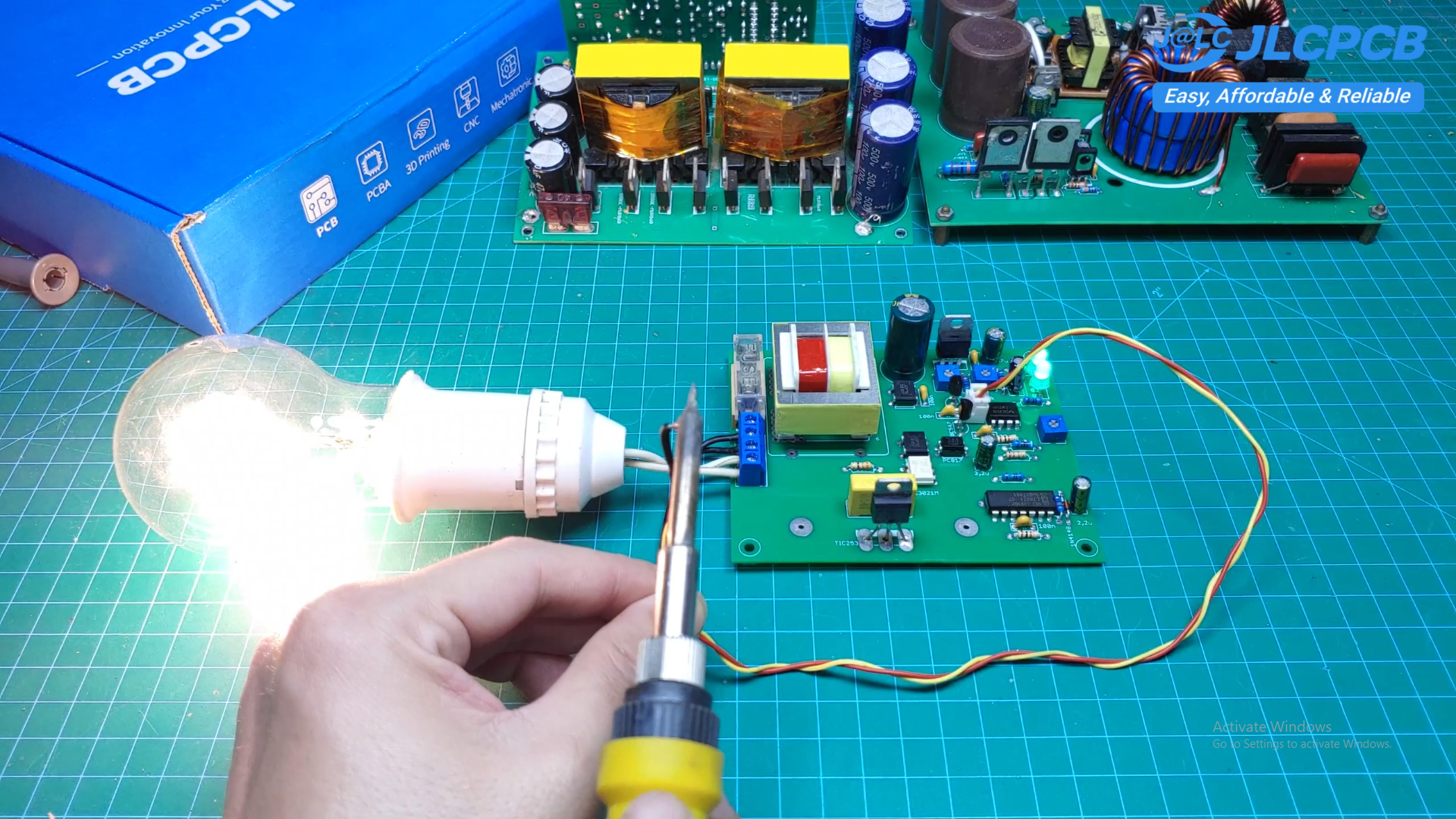
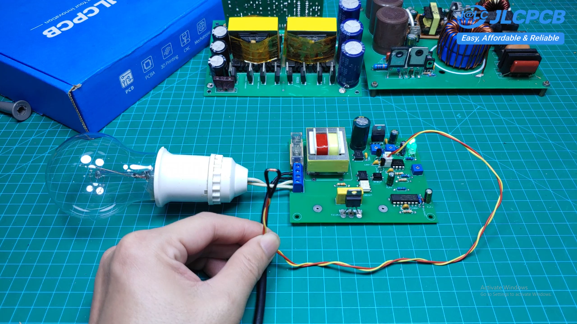
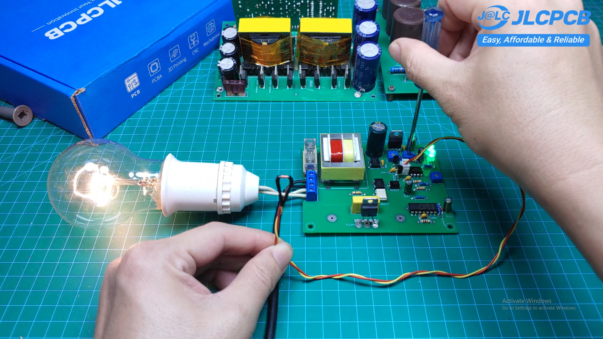
When the temperature is below the set value, the circuit supplies power to the heater.
As the temperature increases and reaches the preset value, the control circuit reduces or turns off the heater power.
When the temperature falls below the set point again, the heater is powered on again.
This allows the circuit to maintain the temperature automatically.
Testing With an Electric Iron
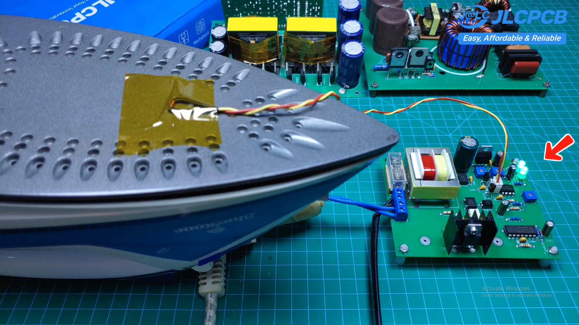
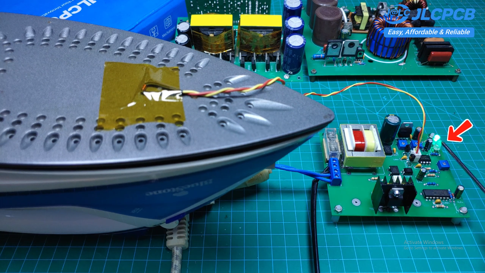
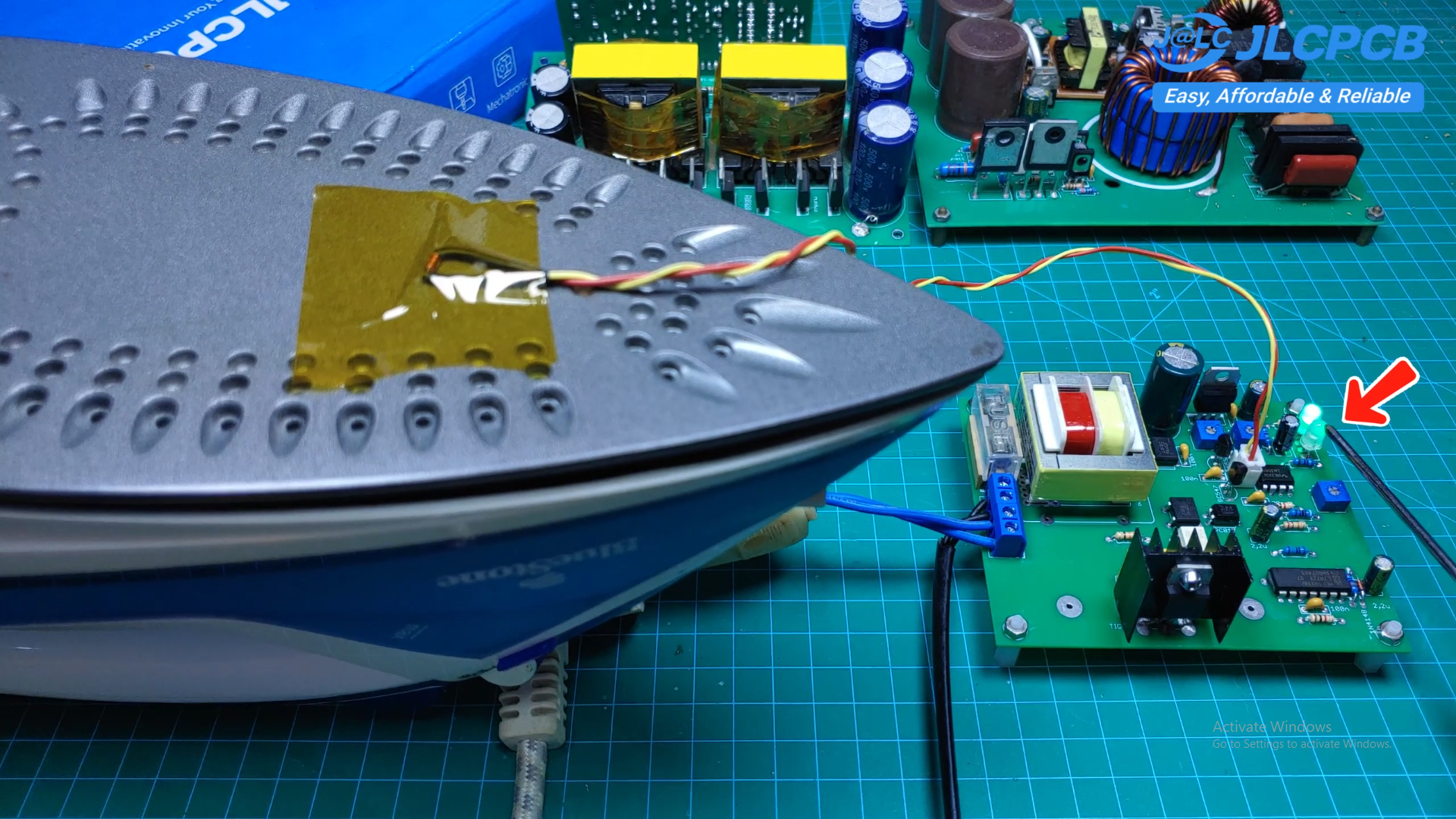
For the practical test, I used an electric iron as the heating load.
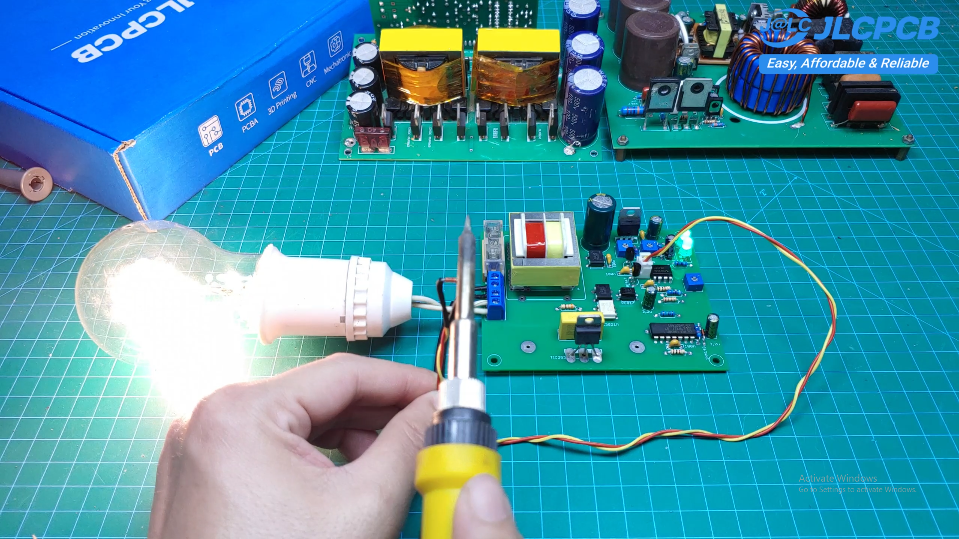
To make the operation easier to see, I also used a light bulb as an indicator.
When I heat the KYT84 sensor, the sensor temperature increases and the circuit turns off the heater.
When I remove the heat source, the sensor gradually cools down. Once the temperature falls below the set value, the circuit turns the heater back on.
This demonstrates the basic operation of the temperature feedback system.
0–100% Power Control
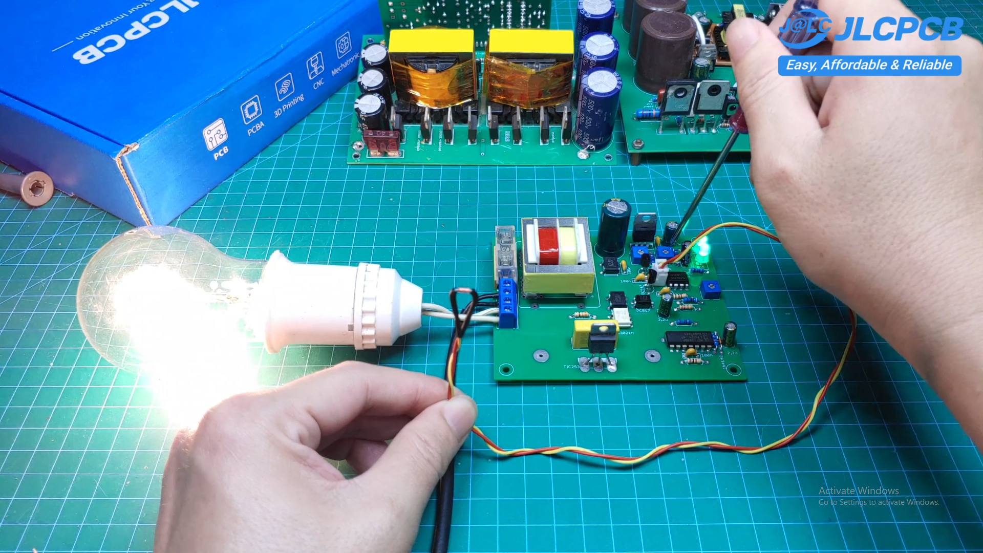
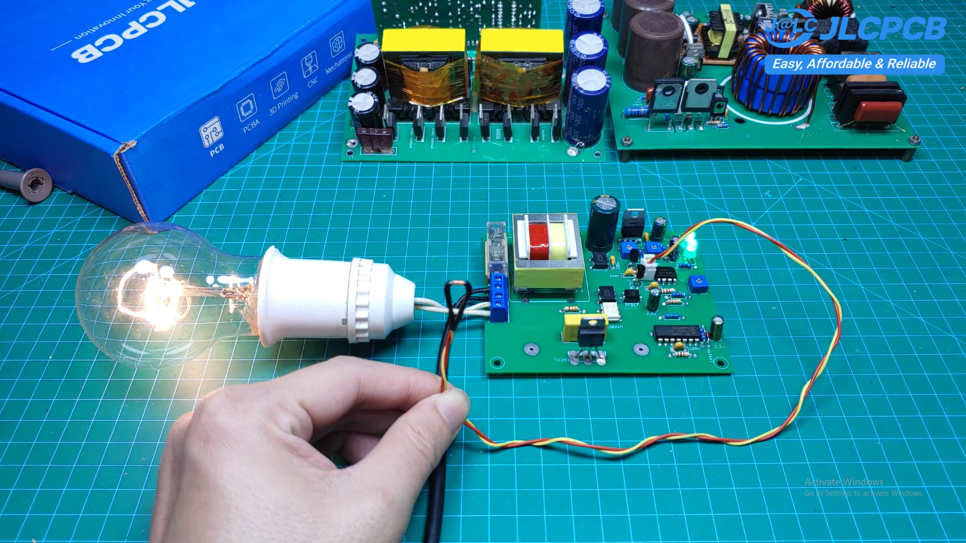
One of the useful features of this circuit is the adjustable output power.
The power delivered to the heater can be adjusted from 0 to 100 percent, making the circuit suitable for many different heating applications.
This can be useful for:
- Electric irons
- Hot plates
- Food warmers
- Heating elements
- DIY reflow or heating plates
- Temperature-controlled heaters
- Other AC heating devices
In the future, I plan to develop this circuit into a dedicated heating plate for soldering surface-mount components.
PCB
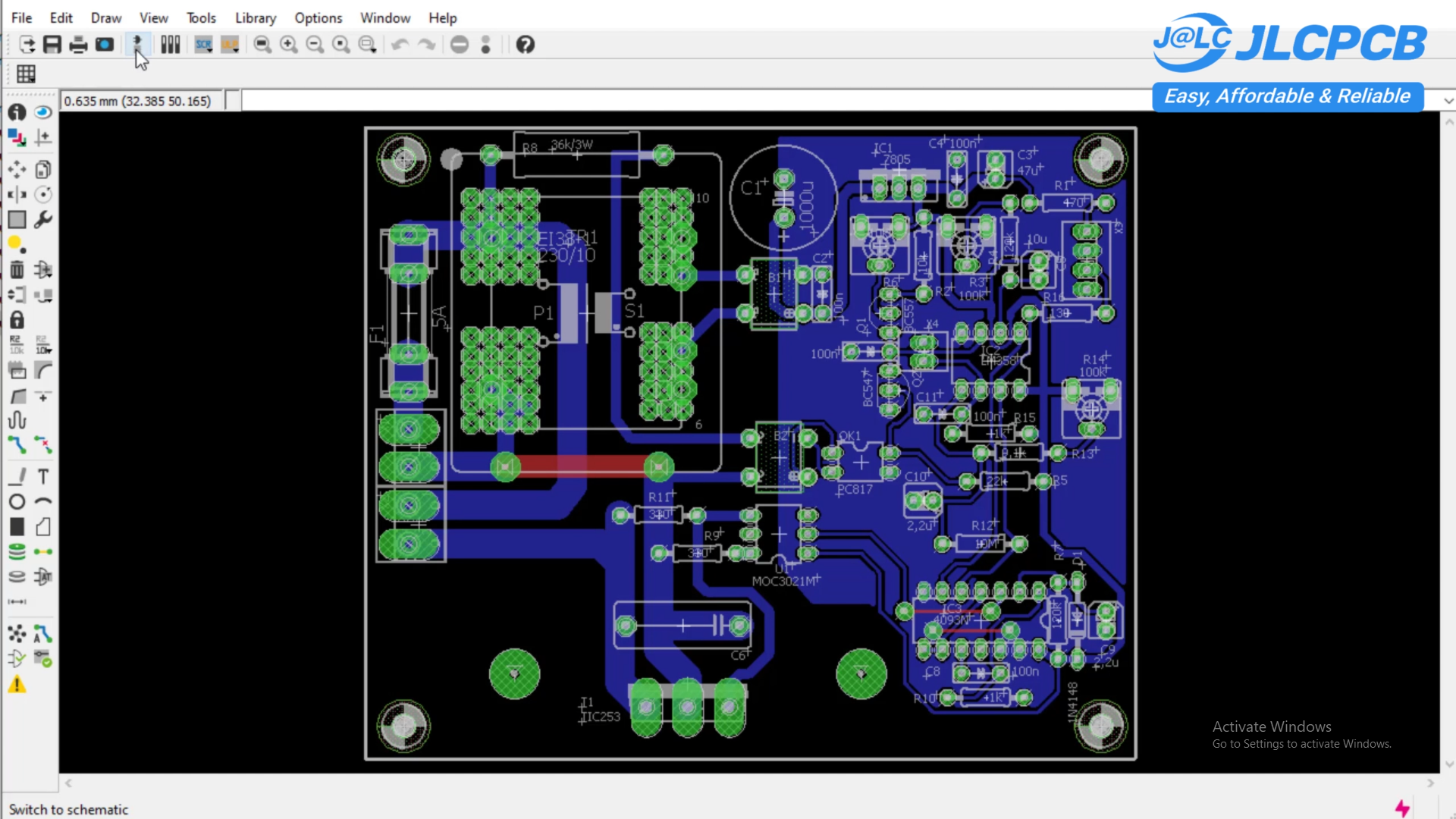
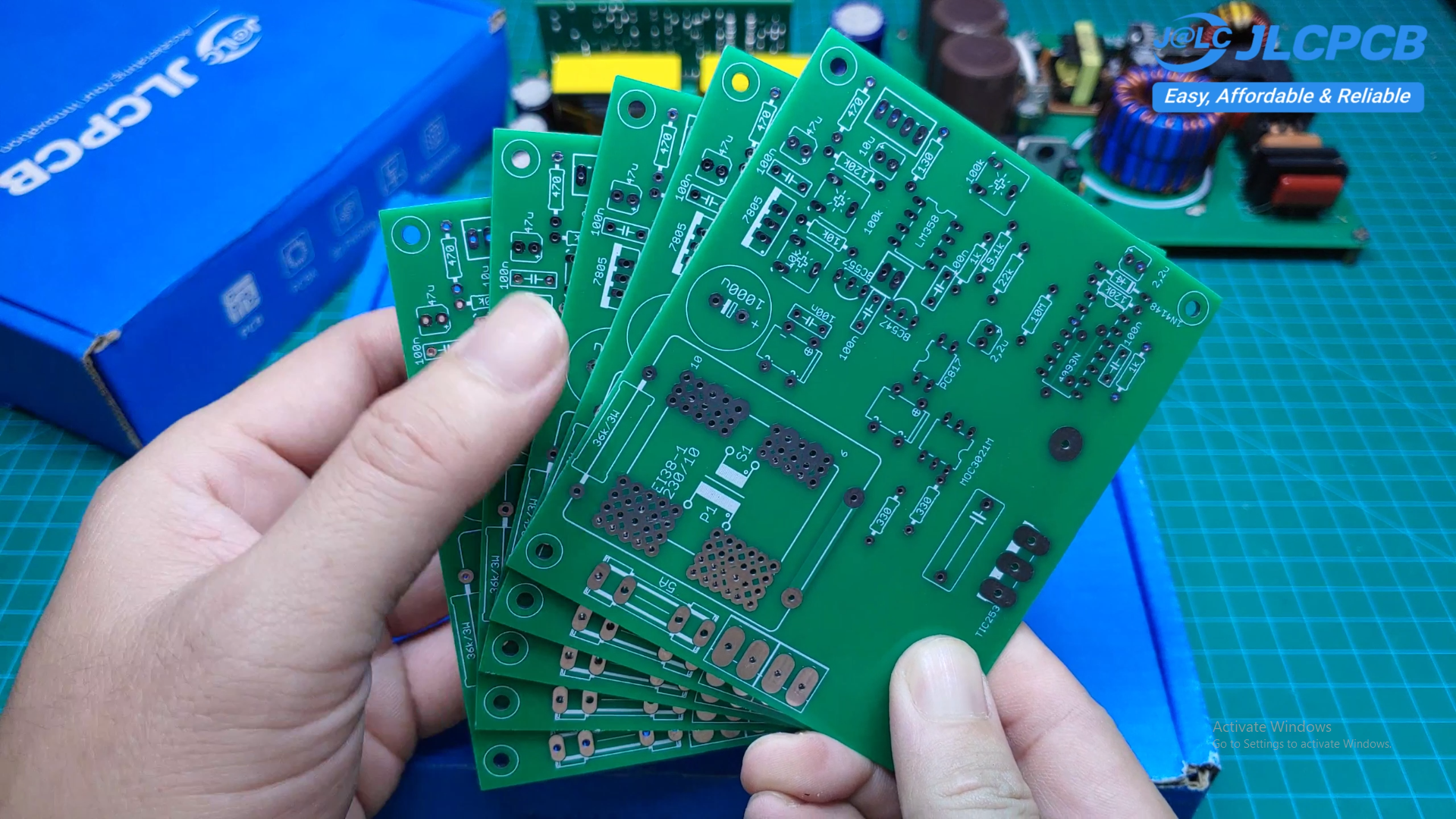
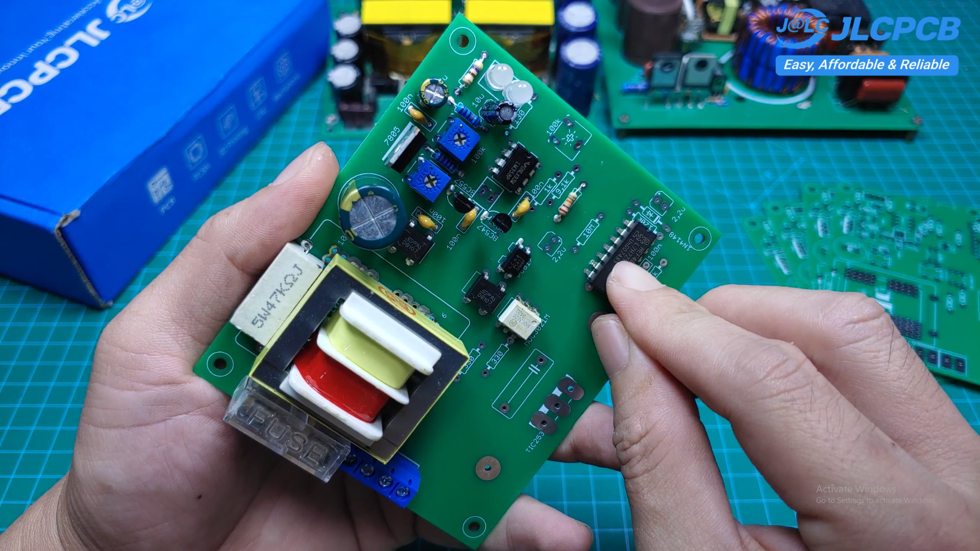
I designed a dedicated PCB for the project to make the circuit compact and easier to assemble.
The PCB was manufactured by JLCPCB, and I was very impressed with the quality of the finished board.
The components are arranged into separate functional sections, making the circuit easier to assemble, test, and troubleshoot.
Project Files
I have also shared the project files, including the schematic and Gerber files.
You can download the files and build your own version of this temperature controller.
This project demonstrates how a relatively simple analog circuit can be used to create an automatic temperature controller without using a microcontroller.
The combination of the KYT84, LM358, CD4093, MOC3021, and TRIAC provides a practical solution for controlling AC heating devices.
There are still many possibilities for improving and developing this circuit, and I hope this project gives you some ideas for your own electronics projects.
Thanks for reading, and I hope you enjoyed this project!
⚠️ Safety Warning: This circuit works with AC mains voltage. Always use proper isolation, insulation, fuses, and safety precautions when testing or building the circuit. Do not touch the circuit while it is connected to mains power.