DIY Transparent LED Matrix
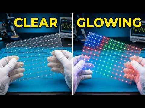
Tired of standard opaque LED matrices? In this project, I'll show you how I designed and built a fully transparent 15x10 LED matrix using 150 WS2812B addressable RGB LEDs on a flexible transparent PCB. The PCB has no ground plane, making it see-through with visible copper traces. I mounted it on a 3D-printed stand and programmed it with colorful animations like rainbow wave, cylon scanner, and fireworks effects.
Supplies
Electronics:
- 150x WS2812B addressable RGB LEDs
- Custom transparent flexible PCB (designed in Altium)
- Arduino Uno or compatible board (data pin to pin 9)
- 5V power supply (2-3A minimum)
Tools & Software:
- Altium Designer (or Altium Developer for online access)
- JLCPCB (for PCB fabrication with SMT assembly)
- Arduino IDE (with Adafruit_NeoPixel or FastLED library)
- 3D printer (PLA filament for stand)
3D Printed Parts:
- Stand (STL link below)
Design the Schematic & PCB
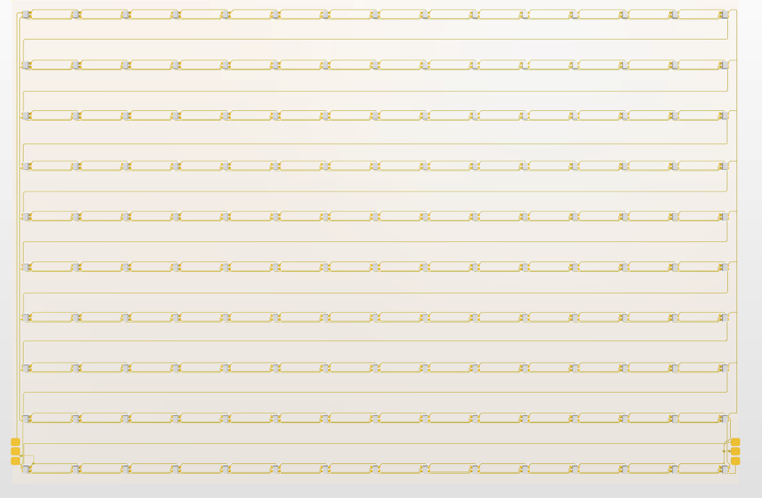
I started in Altium Designer by creating a straightforward schematic. The circuit consists of 150 WS2812B LEDs arranged in a 15x10 matrix. I connected the Data Output of one LED to the Data Input of the next, chaining them together, and tied all VCC pins together and all Ground pins together. I annotated the pixels from 1 to 150 to help with PCB layout.
For the PCB layout, I measured a 20cm x 13cm outline. I used Altium's PCB arrangement tools to distribute the pixels evenly across the board. I gave access to the first and last pixel's data pins, VCC, and GND so I could control and power the matrix.
Important: I did not use a ground plane to keep the circuit transparent.
You can access the Altium design files online here: Altium Project Link
Downloads
Order the Transparent PCB
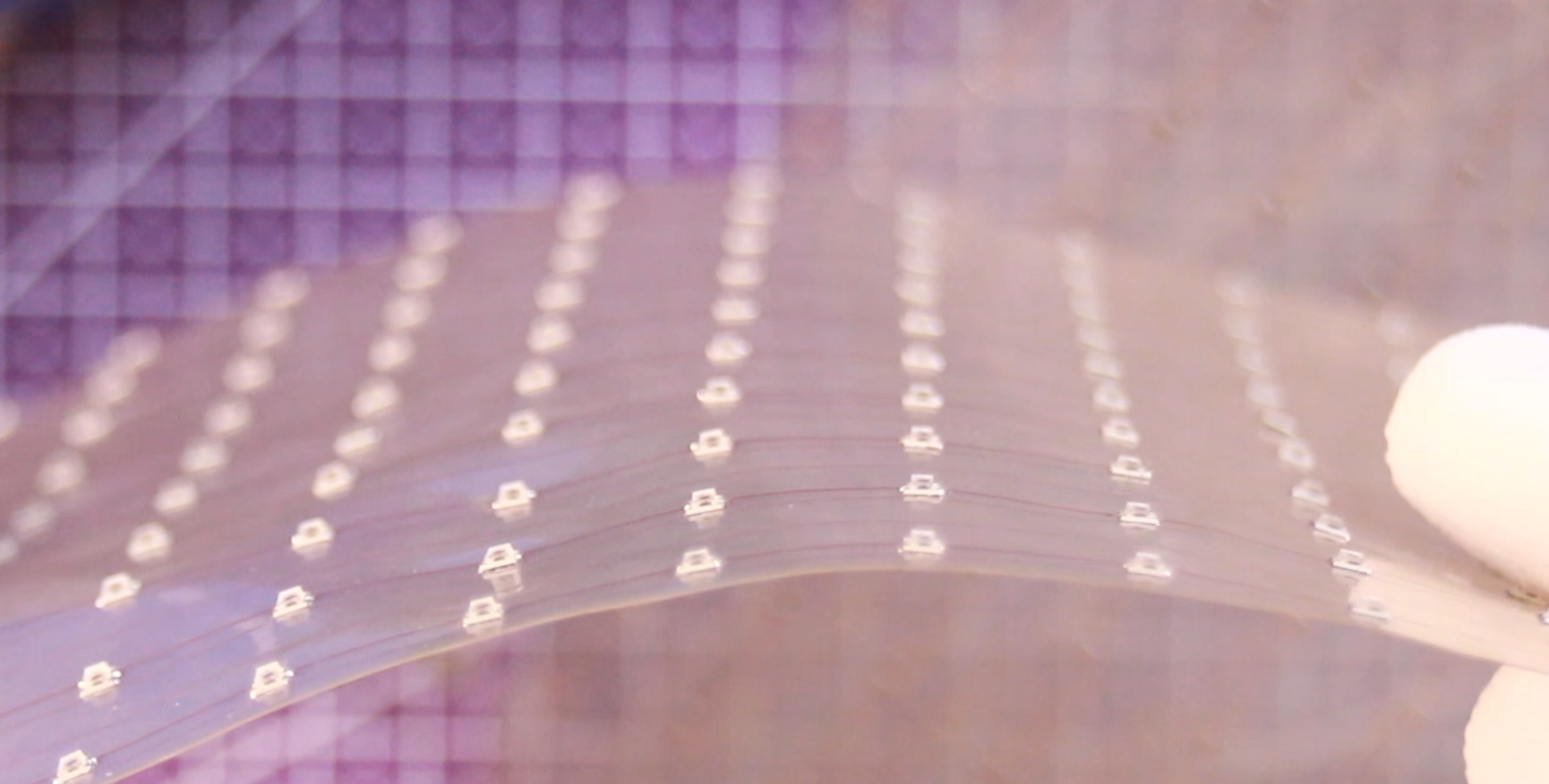
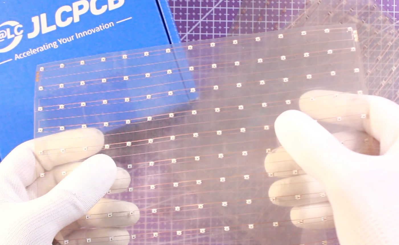
For ordering, I moved over to JLCPCB. I uploaded the Gerber files, selected Flex material, set the substrate type to Transparent, and left the other parameters at default. I also selected the SMT assembly feature to have the matrix assembled by them.
A few days later, I received the circuit very well produced and neatly assembled, with no residual assembly material. The PCB has a clean, transparent look—you can even see through to the copper traces.
Test the Matrix
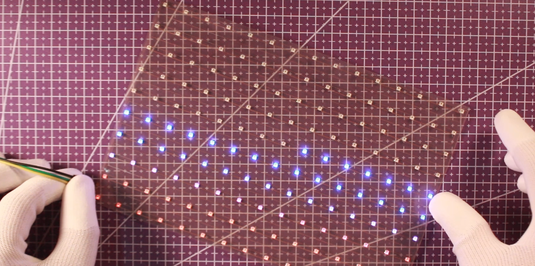
Since I gave access to the first and last connected pixels, I could quickly test the matrix using my Arduino Uno board running a FastLED sketch. The LED matrix started displaying cool animations, and the pixels looked amazing in this transparent layout.
Required Library: Install Adafruit_NeoPixel or FastLED library in Arduino IDE.
Mount the Matrix & Final Assembly
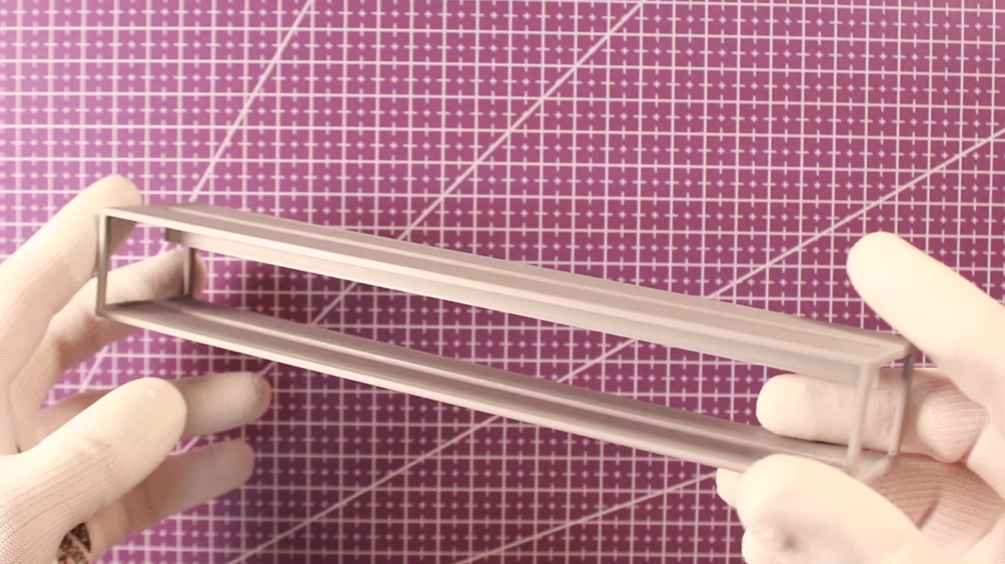
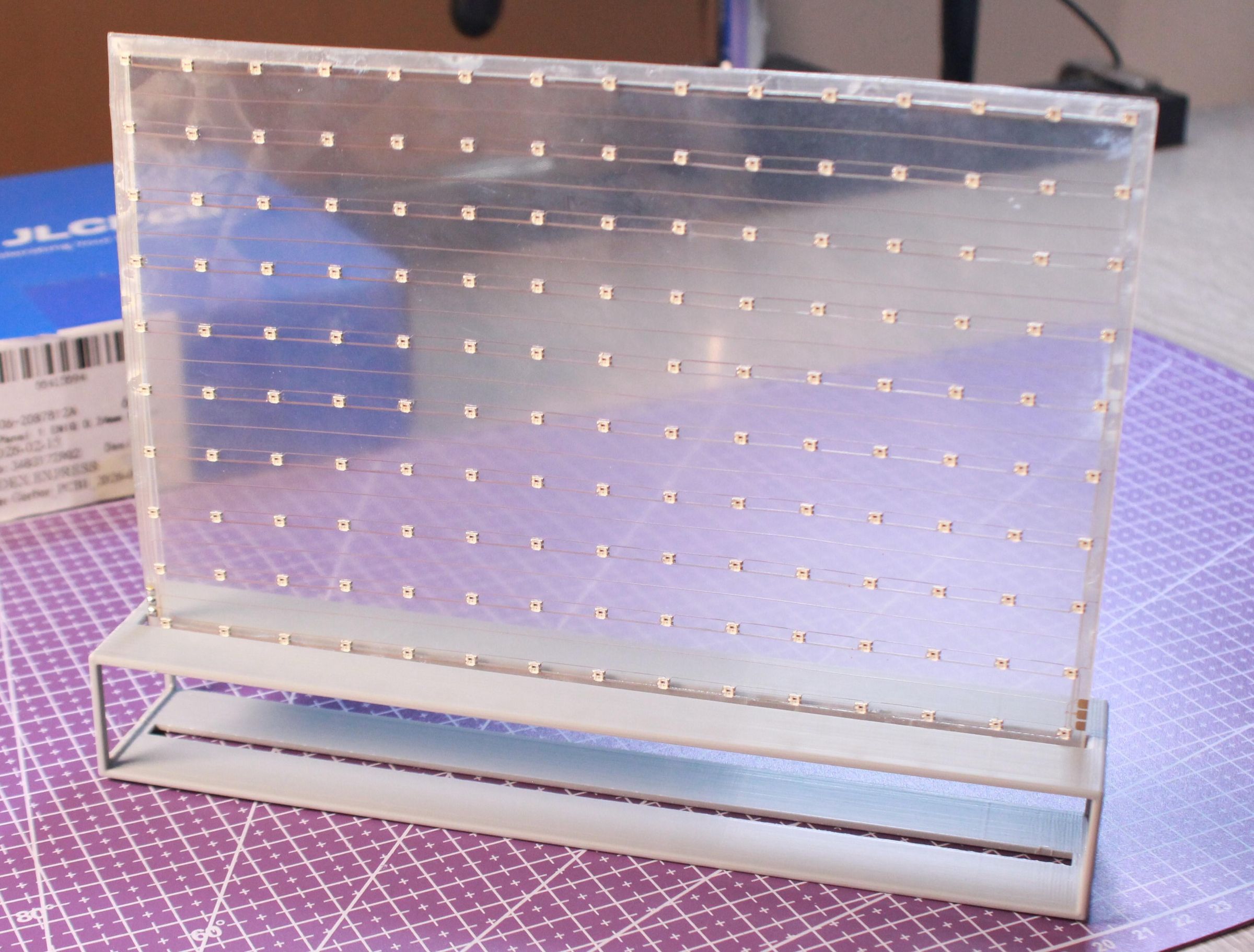
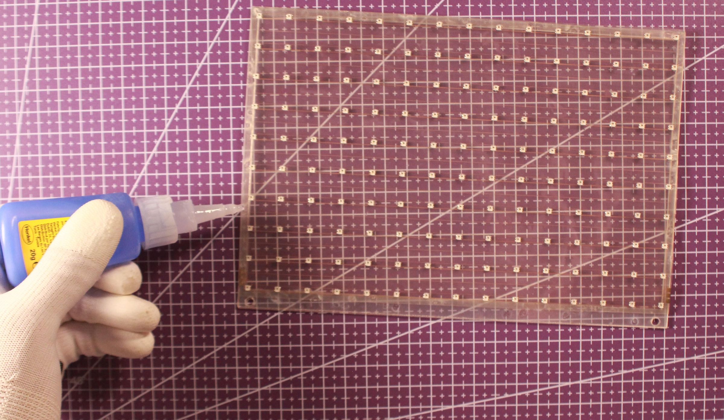
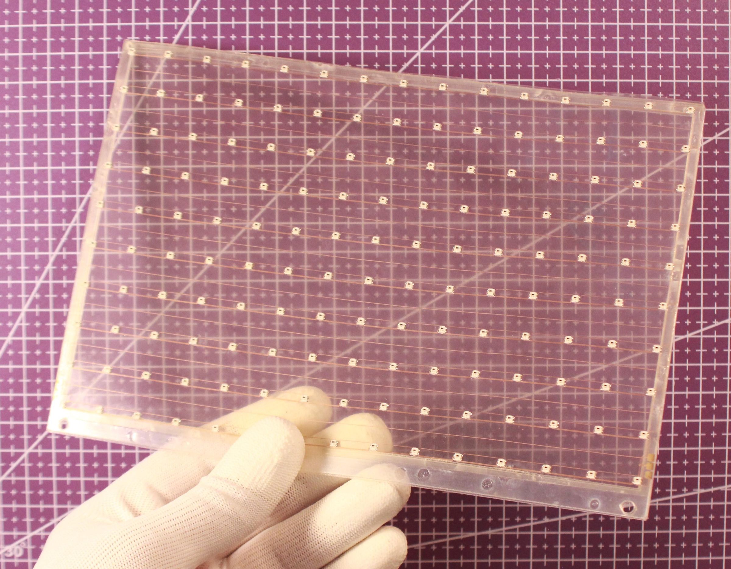
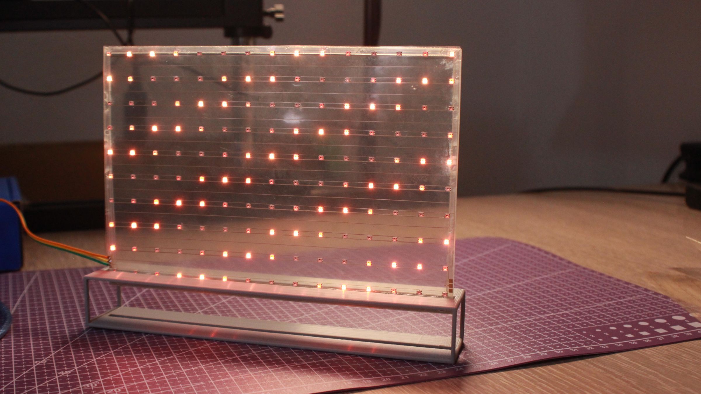
I designed a stand to stick the matrix to it and 3D printed it in PLA filament. Then I used a transparent flex frame to give the matrix more rigidity. I glued the frame to the matrix using super glue, and then glued the frame to the stand.
I can power the circuit and control it from the access port I designed. The matrix runs smoothly, and this design concept could lead to more ideas—it could stick to surfaces thanks to the circuit's flexible material.
Download STL for Stand: Stand.STL