DIY Ultrasonic Pest Repeller
by GreenPAK™ in Circuits > Electronics
21 Views, 0 Favorites, 0 Comments
DIY Ultrasonic Pest Repeller

This Instructable describes the implementation of motion trigger-able ultrasonic repeller. The design uses an SLG46140V GreenPAK™ IC. The input from a PIR (Passive Infra-Red) will be connected to a digital input pin and the output of an Oscillator will be from a digital output pin. The pulse input from the PIR will be delayed and the output from an Oscillator running at 2000 kHz will be scaled down to 21 kHz and 24 kHz producing 2 alternating tones that are irritating to pests.
Below we described steps needed to understand how the solution has been programmed to create a pest repeller. However, if you just want to get the result of programming, download GreenPAK Designer software to view the already completed GreenPAK Design File. Plug the GreenPAK Development Kit to your computer and hit the program to create the amplifier.
Ultrasonic Transducer Background


Animals respond to ultrasound and avoid its presence. Small mammals like dogs and cats respond to 22-25 kHz, rats to 60-72 kHz, insects like mosquitoes & Flies to 38-44 kHz. Ultrasound is biologically safe to human beings according to scientific information. But Ultrasound frequency close to 30kHz can be sensed by children to a certain level. So it is recommended not to use such devices continuously near children below 5 years (Kumar, n.d.).
The Piezoelectric ultrasonic transducer design features a piezo ceramic disc that is resonant at a nominal frequency of 20–60 KHz and radiates or receives ultrasonic energy.
They are distinguished from the piezo ceramic audio transducer in that they produce sound waves above 20 KHz that are inaudible to humans and the ultrasonic energy is radiated or received in a relatively narrow beam.
The “open” type ultrasonic transducer design exposes the piezo bonded with a metal conical cone behind a protective screen. The “enclosed” type transducer design has the piezo mounted directly on the underside of the top of the case which is then machined to resonate at the desired frequency. (Corp, 2005).
When an electrical potential is placed across the Piezo material, the geometry changes thereby disturbing the acoustic surface. When an oscillating electrical potential is placed across the Piezo material, the acoustic surface generates an acoustic signal. When receiving an ultrasonic signal, the ultrasonic waves strike the acoustic surface thereby compressing the Piezo material.
Piezoelectric materials vibrate in response to alternating voltages of certain frequencies applied across the material. Piezoelectric elements are similar to common analog capacitors in that piezo elements generally include two electrodes separated by a piezoelectric material that functions as a dielectric, shown in Figure 1 and the sensitivity with respect to frequency is described in Figure 2 (Corporation, 2006).
PIR Detector
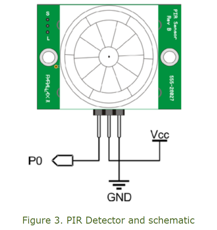
The PIR (Passive Infra-Red) sensor is a pyroelectric device that detects motion by sensing changes in the infrared (radiant heat) levels emitted by surrounding objects. This motion can be detected by checking for a sudden change in the surrounding IR pattern. When motion is detected the PIR sensor outputs a high signal on its output pin. This logic signal can be read by a microcontroller or used to drive an external load (inc, 2014). Refer to PIR Sensor part number: 555-28027 datasheet for complete technical specifications. Figure 3 shows a typical circuit to interface this PIR detector, where Vcc can be in the range of 3.0 V to 6.0 V DC and P0 is the output. The PIR Sensor requires warm-up time which can be up to 40 seconds.
Implementation of Triggered Ultrasonic Transmitter Using GreenPAK Designer Software


Figure 4 shows the Green PAK Designer schematic and its external connections to the PIR detector and piezo buzzer (ultrasonic transmitter).
Figure 5 shows the configuration setting for the 2000 kHz oscillator and 108 Hz oscillator. The pulse output from PIR detector is connected to digital input pin 6 of the GreenPAK device.
In this Instructable, two counters are used to divide clock output from RC OSC which is 2000 kHz to produce 21 kHz and 24 kHz.
The CNT0/DLY0 is a 14-bit counter and it divides the clock by 45, resulting in 43 kHz clock which is further divided by a DFF 4 to produce ~21 kHz. Similarly CNT1/DLY1 8-bit counter is configured to divide the clock by 40, which is further divided by DFF5 to produce 24 kHz. The 108 Hz output from LF OSC is also divided by CNT3 to generate a 2Hz clock which is further divided by a DFF latch to generate 1Hz that is used to toggle select input of the Mux 3-L2. The Mux inputs are connected to 21 kHz and 24 kHz sources. The delayed PIR trigger is ANDed with Mux output. The configuration settings of the Oscillators and Counters are shown in Figure 5 and Figure 6.
Whenever PIR detects a pest’s movement in front of its region of sensing, the GreenPAK device will produce annoying 24 kHz and 21 kHz alternating sounds which has proved to be irritating to both cats and dogs.
SLG46140V Oscillators
The SLG46140V has two internal RC oscillators (25 kHz or 2 MHz, user selectable), as well as one Low-Frequency oscillator (1.9 kHz) and one Ring oscillator (25 MHz). In this application only two oscillators will be used: RC OSC whose clock frequency of 2 MHz will be divided down and used to drive the transducer, and clock frequency of 1.743 kHz output from LF OSC will be used as reference clock to create delay in the 8-bit CNT1/DLY1 as shown in Figure 5.
Both of these Oscillators RC OSC and LF OSC can be turned on by:
- Register control (force power on);
- Delay mode, when delay requires OSC;
- ADC;
- PWM/DCMP.
Counters/Delay Generators (CNT/DLY)

There are two configurable counters/delay generators in the SLG46140V. One of the counter/delay generators (CNT/DLY0) is 14-bit,and the other counter/delay generator (CNT/DLY1) is 8-bit. In this application CNT/DLY1counter/delay is used which has one input from the connection matrix, which has a shared function of either a Delay Input or an external clock input. As shown in Figure 7, if a DLYOUT is required which is delayed output of the falling edge of DLYIN, Delay Time can be set as shown in Figure 5 configuration. This delay time is increased or decreased using Counter data. For this application it is set to 50 which creates a delay time of 29.8 ms.
Testing Ultrasonic Repeller


Figure 8 shows the testing setup for this application. The PIR detector has been connected to work at +5.0 V as shown in Figure 4. The Oscilloscope channel 2 is connected to the PIR output whereas channel 1 is connected to PIN 9 of the GreenPAK device. The GreenPAK emulator is turned on to observe the output. Figure 9 shows the Proto-board wiring of PIR supply.
Figure 10 shows the Oscilloscope screenshot of the PIR pulse output.
Figure 12 shows the output when PIR detects movement multiple times. Notice the response is only on the positive edge of the PIR pulse.
Refer to pin labelled “1st_Freq” in Figure 4 Schematic.
Further Improvements and Modifications
This application can modified to include more than two frequencies that can ward off other pests like Deer and also repel insects. The settings for effective Ultrasound is as follows: 38 kHz -44 kHz for Mosquitoes, Fleas, House Fly, Spiders, Cockroaches. 52-60 kHz for Lizards. 60-72 kHz for Rats (Kumar, n.d.). To make this application more effective, additional ultrasonic emitters and PIR sensors can be designed in, as can be laser perimeter detectors. Power efficiency for outdoor versions can be achieved by recharging the batteries of a small unit with solar cells.
Conclusion
The small size and low power consumption of GreenPAK SLG46140V makes it ideal for a small size module that can be installed more easily, and be less visually obvious. The usage advantage of GreenPAK is flexibility to tune, modify, enhance the circuit, and zero coding for a robust design.
References
1. Corp, P.-W. E. (2005). Selection and use of Ultrasonic Transducers. AN050830, 8.
2. Corporation, P. W. (2006). Air Ultrasonic Ceramic Transducers. 250ST/R160.
3. inc, P. (2014, 3 27). Parallax inc. Retrieved from PIR Sensor: www.parallax.com
4. Kumar, D. M. (n.d.). Electro Schematics. Retrieved from Ultrasound and Insects: www.parallax.com
5. Dialog Semiconductor. Official website