DIY Wave Projector
by maximiliandeweese in Circuits > Raspberry Pi
1649 Views, 3 Favorites, 0 Comments
DIY Wave Projector
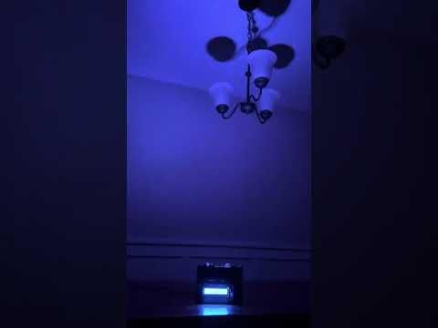
Bring vibrant colors to life with this DIY Programmable LED Wave Projector! Using a Raspberry Pi and a rotating RGB LED ring, it creates mesmerizing rainbow-inspired lighting effects while giving you complete control to customize and program your own animations.
Supplies
Materials:
- Black PLA filament
- Raspberry Pi 4 Model B
- Small 5v DC Motor
- TB6612FNG Motor Driver
- KY-023 Dual Axis XY Joystick Module
- 1602A LCD Display Module with I2C Backpack
- Freenove ADS7830 ADC
- 5.1V 3A DC Raspberry Pi compatible power source
- 1/8th inch wave acrylic
- 9 608RS bearings
- Jumper Wires
- 16 bit WS2812 LED ring
- Zip ties or Electrical Tape
- Small Distribution Board
Tools:
- 3D Printer
- VS Code with SSH to Raspberry Pi enabled
- Screw driver
- Scissors
- Soldering Setup
Project Overview


Create your own programmable LED Wave Projector using a Raspberry Pi, rotating acrylic, a WS2812 LED ring, and a custom 3D-printed enclosure. The projector casts colorful, moving light patterns that resemble flowing ocean waves, making it perfect for ambient lighting.
The effect is created by shining individually addressable RGB LEDs through a textured diffuser that slowly rotates. As the LEDs change color and the diffuser spins, the light is scattered into smooth, flowing patterns that can be fully customized in Python.
This guide covers everything from 3D printing and assembly to wiring and programming. Once complete, you can choose from multiple built-in animations or create your own custom lighting effects in Python.
Print the Parts

Print all of the provided STL files using black PLA filament. I recommend a 0.4 mm layer height with 10–20% infill.
Once all of the parts have been printed, remove any support material and test-fit the components. The bearings, motor, LED ring, and acrylic diffuser should fit snugly without requiring excessive force.
The CAD files can be found here:
https://drive.google.com/drive/folders/1Y9RpRu_eRS8P4QHu-o5bUtnApUR7X-Ge?usp=sharing
Assembling the Acrylic Casing


You should have the inner rail with the large bevel gear, a sheet of 1/8th inch wave acrylic, and the thin top ring. Cut the 1/8th inch wave acrylic carefully with scissors until you have a circle with a diameter between 5.2 and 5.6 cm.
Now that the acrylic is cut, it's time to permanently set it into the inner rail. Place the wave acrylic circle into the inner rail. Next, heat the thin top ring until it's slightly soft - you can use the heat bed of your printer - and finally twist/ push it in until the top of the inner rail is smooth. Once the top ring cools, it should be permanently joined with the inner rail, embedding the acrylic flatly inside.
Assembling the Acrylic Diffuser Turret

Begin by pressing the 9 608RS bearings onto their pegs. Next, place the inner rail with the acrylic inside between the bearings. The axis of rotation of the inner rail should be 45 degrees to the axis of rotation of each bearing. Once the bearings and inner rail are seated, screw in a washer on top to keep them from falling out.
Additionally, it's time to press fit the small bevel gear onto the motor. Heat the inner hole of the bevel gear until it's soft and slightly expanded, then press the motor shaft inside with a decent amount of force. After the small bevel gear cools, it should be firmly attached to the motor's shaft.
An image is attached of what your wave projector should look like at this point; additionally, the motor is placed inside to show the large and small bevel gears connecting at a 90-degree angle. They should produce a 4.72:1 gear reduction from the motor.
Soldering the Electronics

It's now time to solder the electronics. Pins or wires should be soldered onto each component so they can be connected to the rest of the circuitry. It is highly recommended to watch a tutorial online if this is your first time soldering. You may need to solder fewer or more items depending on what you buy, but here's a checklist of items you might need to solder:
- Soldering Pins onto the TB6612FNG
- Soldering female ends of jumper wires onto the 5vDC motor's wires
- Soldering female ends of jumper wires onto the 5vDC, GND, and DI pads of the WS2812 LED ring
A picture of properly soldered pins on the TB6612FNG is attached. Before the end of this step, ensure that each electronic component's ports have pins, male or female jumper connections at the end for ease of wiring later.
Mounting the Electronics


Congrats! Now it's time to mount the electronics.
Mounting the Motor:
Place the motor within its mount and secure it via a zip tie around the flexible rim. Next, attach the motor mount to the lower frame with 2 screws. An image of this is provided below.
Mounting the LED:
Attach the circular LED to its mounting tray. Now attach the circular LED's mounting tray to the lower frame with 3 screws, placing a spacer between them.
Mounting the Raspberry Pi 4:
The Raspberry Pi 4 will be mounted to the bottom plate. Be careful not to bend the chip when attaching. Later, we will screw the bottom plate onto the lower frame after connecting the electronics.
Mounting the 1602A LCD and Joystick:
The 1602A LCD and the Joystick have their own mounting plate separate from the lower frame. After screwing these components into their mounting plate, attach the mounting plate to the lower frame through a screw at the edge.
Completing the Wiring


Now it's time to connect all of the electrical components together! It's recommended to follow a consistent color coding for the wires throughout the project. We handle 5v, 3.3v, GND, SCL, SDA, and other info wires throughout the project, and a color was assigned to each: red for 5v, orange for 3.3v, black for GND, purple for SDA1, and brown for SCL1.
Because multiple components need to connect to the Pi's 3.3v, 5v, GND, SDA, and SCL pins, I would use a small distribution board to make the wiring cleaner. I made my own by soldering pins and jumper wires onto some perfboard.
Wiring the GUI:
Circuit diagrams from Feeenove are provided.
For the 1602A LCD, connect the 5v wire to the Pi's 5V power source and your GND to the Pi's GND through the Pi's pins. Then connect the display's SDA and SCL pins to the Pi's SCL and SDA pins.
For the KY-023 Dual Axis XY Joystick, connect the 5v wire to the Pi's 5v power source and the GND to the Pi's shared GND. You can ignore the SW wire, as button presses from the joystick are ignored. Connect the VRX and VRY wires to the A0 and A1 pins on the Freenove ADS7830 ADC, respectively. The ADC converts from Analog to digital, so the Pi can read the joystick's vertical and horizontal position. Connect the SDA and SCL pins on the ADC to the Pi, respectively, and provide the ADC with power through 3.3v in VCC, and connect GND to GND. You can ignore the wiring with the resistor and the SW pin in the circuit diagram, as joystick button presses are not read.
Wiring the LED Ring and Motor:
Connecting the 16-bit WS2812 LED ring with the rest of the circuitry is easy. Provide it with power by connecting GND and 5v. Then connect DI to your desired GPIO pin on the raspberry Pi. I chose GPIO 13 (Pin 33). The official GPIO pinout diagram from the Raspberry Pi is attached.
Connect the DC motor to the AO1 and AO2 terminals on the TB6612FNG motor driver. Then, connect the TB6612FNG motor driver's VM pin to the 5V rail, VCC and STBY to the Raspberry Pi's 3.3V rail, and GND to the common ground. Finally, connect the control pins from the motor driver to the Raspberry Pi's GPIO pins. I chose PWMA > GPIO12 (Pin 32), AIN1 > GPIO23 (Pin 16), and AIN2 > GPIO25 (Pin 22). These GPIO pins allow the Raspberry Pi to control the motor's speed and direction through the TB6612FNG.
Install Raspberry Pi OS
Flash Raspberry Pi OS onto a microSD card using Raspberry Pi Imager and complete the initial setup. Enable SSH during setup so the Raspberry Pi can be accessed remotely from your computer.
Install Required Software and Configure Project
Connect to the Raspberry Pi using VS Code over SSH. Install Python and the required libraries, then download or clone the project files to the Raspberry Pi.
Open the project in VS Code and verify that the GPIO pin assignments match your wiring. If you changed any connections during assembly, update the corresponding values in the source code before running the program. Also ensure that the I2C ports are set up correctly.
Python Code
Step 9: Python Code
The projector is controlled by several Python files, with each file handling a different part of the system. This keeps the code organized and makes it easier to modify individual components.
The main files are:
- main.py starts the projector and connects all of the other programs together.
- LED_controller.py contains the different LED animations.
- motor_controller.py controls the motor’s speed and direction.
- GUI_controller.py reads the joystick and displays the selected animation on the LCD.
- ADC.py reads the joystick’s analog VRX and VRY signals through the ADS7830.
Open the project folder in VS Code using the Remote SSH connection to the Raspberry Pi. Copy the provided Python files into the same folder and check that the GPIO assignments match the wiring used earlier in the guide.
The LED ring is configured as a 16-pixel NeoPixel ring connected to GPIO13. Each animation changes the red, green, and blue values of the individual LEDs to create effects such as Ocean, Aurora, Nebula, Lava, Rainbow, and Sparkle.
The motor controller uses GPIO12 for PWM speed control, while GPIO23 and GPIO25 control the motor direction. When the program starts, the motor briefly receives additional power to begin moving before slowing to its normal operating speed.
The LCD and joystick provide the user interface. Moving the joystick scrolls through the available lighting modes, and the selected mode is displayed on the LCD. The program then stops the previous animation and starts the newly selected one.
Run the program from the project directory with sudo python3 main.py
Running with sudo may be required for the Raspberry Pi to control the WS2812 LED ring. To safely stop the program, press Control + C inside the terminal. This allows the shutdown code to turn off the LEDs and stop the motor.
Before closing the terminal or disconnecting power, always make sure the program has stopped and the motor is no longer spinning.