Decibel Meter With Circuit Playground
by aea1368 in Circuits > Arduino
951 Views, 8 Favorites, 0 Comments
Decibel Meter With Circuit Playground

I made a decibel meter! Decibels are units of measurement for sound, and I wanted to make a light indicator to show how loud it is in the room.
It has an on switch, and the noise or loudness sensor is the main input. My three outputs are a green light indicating if the meter is on, the light ring from the circuit playground graphing green, yellow, and red lights based off of the decibel input, and blue light indicating if you should be wearing protective ear plugs based on the loudness of the room.
I am a student at Utah State University! At the college, I am in the Aggie Pep Band that plays at the school’s basketball games. Generally there are over 9,000 people in the Spectrum (the indoor basketball stadium) at the games at a time, and as you can expect, it can get very loud there. I've often wondered how loud it gets in there and how dangerous it is to be exposed to the high decibels for long periods of time. As a musician and music lover, I don’t want to lose my hearing, so I wanted to create a portable decibel reader that tells you if you to be wearing earplugs to protect your hearing.
Supplies

Supplies:
- Arduino Circuit Playground Express
- Attachable battery pack
- 3x AAA batteries
- 2 small LED lights (1 green + 1 blue)
- 4in x 6in cardboard
- Conductive thread
Tools:
- Circuit Playground Data Cable (comes with the basic pack)
- Pencil or Pen
- Scissors
- Craft knife
- Needle
- Clear Tape
Plan Your Design


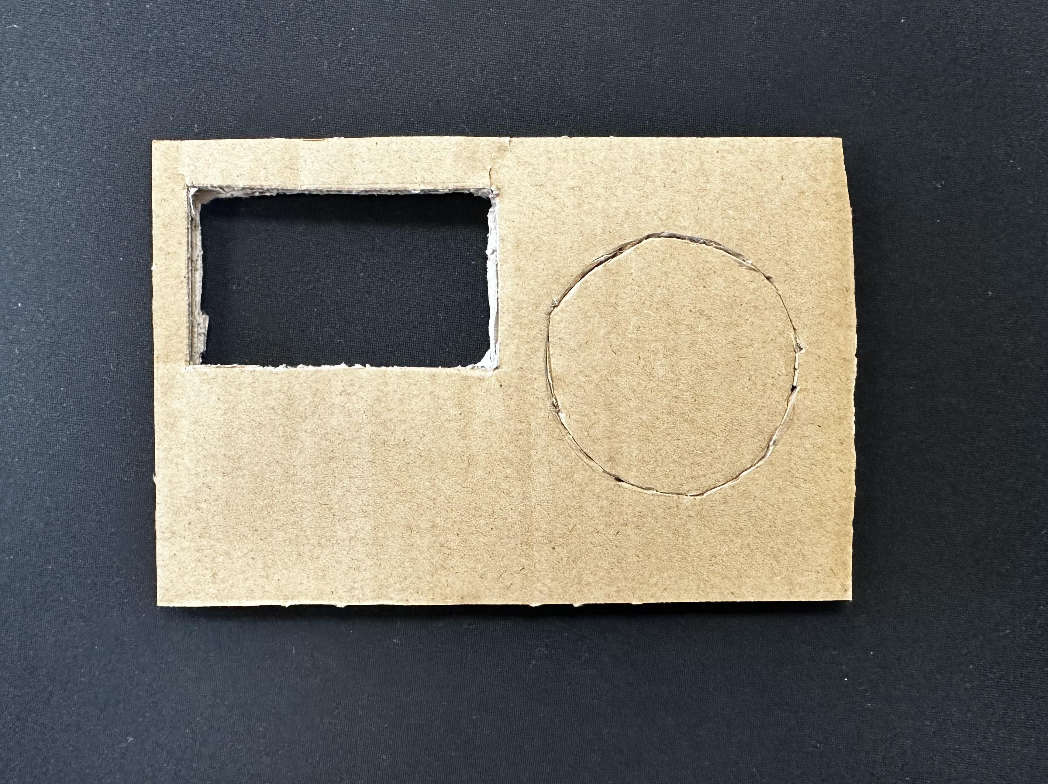
First, you need to see how you want to situate your battery pack and Circuit Playground on the cardboard. For my project, I decided to have the on switch by the corner of the board, but you can put it in any orientation you'd like.
After deciding this, I outlined where I wanted each of the parts to be with my pencil.
Cut Out Battery Pack Outline


From the outline you made last step, use your craft knife (I used a pocket knife) to cut it out so that the battery pack can fit in the hole you make.
It should be a pretty tight fit so try to follow the lines as closely as possible.
Securing the Arduino Onto the Board


.jpg)
Next, get out your conductive thread, needle, and scissors. We are going to secure the circuit board to the cardboard.
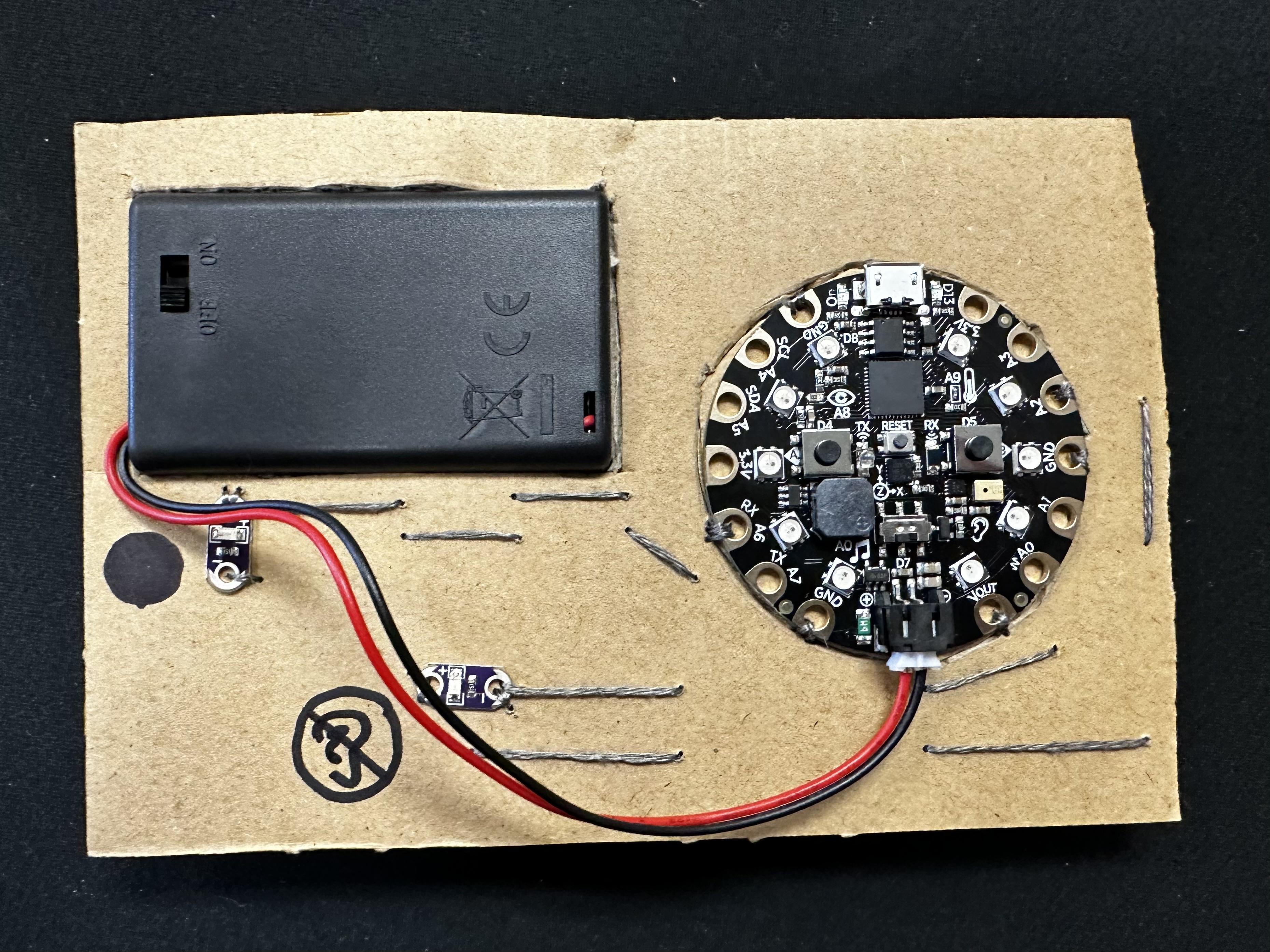
After threading your needle, tie a knot at the end of the thread. We are going to make a couple whip stitches through two unused holes on the Circuit Playground. (As seen in the picture, I used the GND at the top of the board and the VOUT at the bottom of the board)
Tip: Make sure to not connect these two parts of the circuit board together! After making whip stitches in one, tie off the thread and cut it before starting your second set of whip stitches.
Downloading the Code


Here is the download for the code. Once you click on the link, attach the circuit playground to your computer, download the code, and follow the pictured instructions on the website to put the file on the board!
Attaching the First LED (positive Side)


After positioning the green LED where you want it to be (this will be the on-off indicator), use the connective thread to whip stitch a couple of times in the A6 hole. Then about every half an inch, poke your needle to the other side like you're hand sewing fabric.
When you get to the LED light, whip stitch the thread into the positive side.
Attaching the First LED (Negative Side)


Same as with the positive side, we are going to attach connective thread from the board to the negative side of the green LED.
Whip stitch into the GND on the bottom of the circuit playground, hand sew to the LED, and whip stitch into the negative side to secure it into place! Lastly, test the circuit to make sure it was connected properly. If so, it will be on when the switch is set to on.
IMPORTANT: Don't let the positive and negative connective thread touch! If this happens the board will short circuit and it may electrocute you.
Attaching the Second LED


Follow the same process of hand sewing to attach the blue LED (loud sound indicator) to the circuit playground:
A2 -> Positive side
GND (on right side of the board) -> Negative side
Don't forget to test everything was connected properly by turning it on! This blue light will only turn on in loud rooms. You can test this by blowing on the circuit playground to simulate a loud room.
Covering Circuits With Tape


To avoid starting small fires like the one in the first picture, taping down your conductive thread circuits so that positive and negative do not touch might be helpful.
Optional Markings

To make sure people understand what the indicator lights are for, you can choose to label them.
This is only if you are not planning on covering the circuits. I chose to create two different types of coverings: felt and 3D printed material.
Optional Covering: Felt


Materials:
- Felt (any color, but I think grey or black works best)
- Adhesive (pictured is Elmer's glue and Tacky glue, but sewing, tape, or hot glue would also work)
Step 1: First line up where you want the felt to attach to on the back and temporarily tape it in place. I recommend attaching it somewhere around the midpoint so that it overlap stays on the back.
Step 2: Flip the meter to the other side. While feeling with your fingers through the felt, outline holes for the circuit playground, the on/off switch, and the two LED lights.
Step 3: Next, remove the tape from the back and carefully cut out the outlines. Check that the holes match up with your decibel meter.
Step 4: Use your preferred type of adhesive to close up the felt like a present. (I found that Tacky Glue worked best)
Step 5: Complete!
Optional Covering: 3D Printing


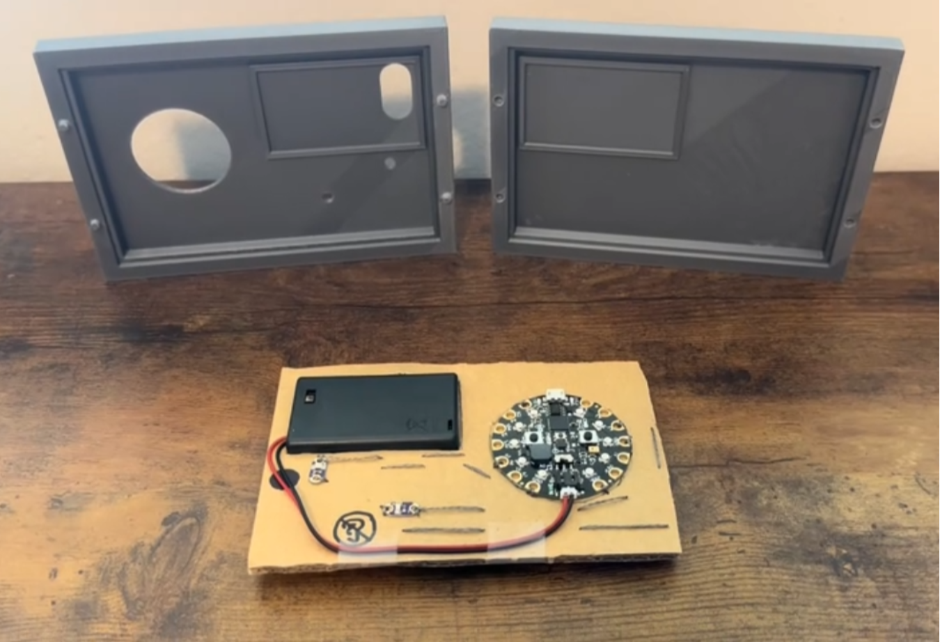
I have an advanced knowledge of 3D modeling. Through a software I am proficient in, Solidworks, I was able to take calipers to make measurements in order to model a case for the decibel meter.
As everyone's project will be slightly different in sizing, the case I made won't work for everyone. But, you can create your own by taking measurements if wanted.
To keep the case closed, I added 4 pegs (2 on the left side and 2 on the right side) and matching peg holes on the other side of the case. Because they had such a low tolerance, friction was enough to keep it together.
I used PLA type filament and it worked just fine for these purposes.