Design and Build a Zener Voltage Stabilizer
by DidierKabelu in Circuits > Electronics
137 Views, 0 Favorites, 0 Comments
Design and Build a Zener Voltage Stabilizer


Imagine that you have a 15 V DC source and need to power a small electronic circuit that requires approximately 5 V.
Simply placing a resistor in series with the load would reduce the voltage, but the output voltage would change as the load current changes.
I wanted a simple solution that could maintain the output voltage around 5 V without using a microcontroller or a complex voltage regulator.
The solution is a simple Zener shunt regulator.
In this project, we will design, build and test a small Zener voltage stabilizer capable of providing approximately 5 V from a 15 V DC source.
Objective
The goal of this tutorial is not only to build a simple Zener diode voltage regulator with the values presented here, but also to learn how to design one according to your own requirements.
By following the steps in this tutorial, you will learn how to:
- Define the required input voltage, output voltage, and maximum load current.
- Select an appropriate Zener diode.
- Calculate the required series resistor value.
- Determine the required power ratings of both the series resistor and the Zener diode.
- Choose standard component values that are suitable for the design.
- Understand how the circuit behaves under minimum and maximum input voltage conditions.
By the end of the tutorial, you should be able to design and build a Zener diode voltage regulator for your own application, rather than simply reproducing the example presented in this project.
Supplies
Components
- 1 × 5.1 V Zener diode
- 1 × 330 Ω / 0.5 W resistor
- Load suitable for the test
- DC power supply
- Veroboard /Breadboard
- Jumper wires (if you are using the breadboard)
- Optional output capacitor
Tools
- Digital multimeter
- Soldering iron, if building on a permanent board
- Wire cutters/strippers
Understand the Circuit
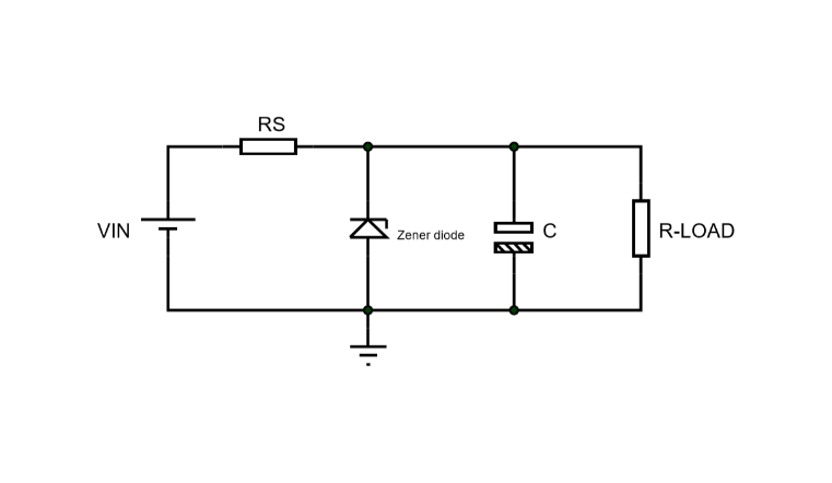
How It Works
The circuit is based on three main elements:
Series resistor(RS) → Zener diode → Load
- The series resistor limits the current flowing through the circuit.
- The Zener diode is connected in reverse bias and in parallel with the load. When it operates in its breakdown region, it maintains a relatively constant voltage across the load.
- The load therefore receives a voltage approximately equal to the Zener voltage:
Vout ≈ VZ
The series resistor absorbs the voltage difference between the input voltage and the Zener voltage while limiting the current flowing through the circuit.
Define the Electrical Characteristics of Your Power Supply
There are three important electrical characteristics to define:
- Input voltage (Vin) and its allowable variation
- Output voltage (Vout)
- Maximum output current (Iout max): it must be higher than the maximum current required by the load.
For example, if the circuit to be powered consumes 20 mA, the maximum current rating of the power supply should be, for example, 20 to 30% higher than the maximum current required by the load.
For this project, the electrical characteristics of our power supply are:
- Vin: 15 V with a ±10% variation
Therefore:
10% of 15 V = 0.1 × 15 = 1.5 V
The minimum and maximum input voltages are:
Vin(min) = 15 − 1.5 = 13.5 V
Vin(max) = 15 + 1.5 = 16.5 V
- Vout: +5 V
- Iout max: 30 mA
Choose the Zener Diode
The choice of the Zener diode will be based on three important parameters:
- Zener voltage (Vz): Choose a Zener diode whose voltage is very close to the output voltage defined in the previous step.
- Minimum Zener current (Izmin): For the calculations, we will use a small value by default, such as 2 mA.
- Maximum Zener power (Pzmax)
For our design, we have chosen:
- Vz = 5.1 V: a standard Zener voltage close to our target output voltage of 5 V.
- Izmin = 2 mA: the minimum Zener current assumed for our calculations.
The maximum Zener power will be determined later, after calculating the series resistor and considering the maximum input voltage.
Calculate the Series Resistor RS
Two important characteristics must be determined:
- Its nominal resistance value
- Its power rating
These two characteristics will be determined under two worst-case conditions: minimum input voltage for the resistance value and maximum input voltage for the power rating.
Why do we consider these two worst-case conditions?
The goal is to choose a resistor that allows sufficient current to flow through the circuit even when the input voltage is at its minimum. At the minimum input voltage, the total current in the circuit decreases, but the load must still receive enough current to operate properly.
1. Calculate the nominal resistance value (at Vin(min))
The resistance is determined from the voltage-loop equation:
Vin − RS × IT − VZ = 0 (1)
where IT is the total current flowing through the circuit:
IT = IZ + Iout(max)
Therefore:
RS = (Vin − VZ) / IT
At Vin(min):
- IZ = Izmin = 2 mA
- Iout(max) = 30 mA
- Therefore, IT(min) = Izmin + Iout(max)
So:
IT(min) = 2 mA + 30 mA = 32 mA
Using:
- Vin(min) = 13.5 V
- VZ = 5.1 V
- IT(min) = 32 mA
We obtain:
RS = (13.5 − 5.1) / 0.032 = 262.5 Ω
The calculated value is therefore approximately 262.5 Ω.
We must choose a standard resistor value that is equal to or lower than the calculated value. This ensures that the current remains sufficient at the minimum input voltage.
A suitable standard value is:
RS = 240 Ω
2. Calculate the power rating (at Vin(max))
The power dissipated by the series resistor is:
PR = RS × IT²
Remember that the total current in the circuit varies with the input voltage. At Vin(max), the current through the resistor is at its maximum:
IT(max) = (Vin(max) − VZ) / RS
Using:
- Vin(max) = 16.5 V
- VZ = 5.1 V
- RS = 240 Ω
We obtain:
IT(max) = (16.5 − 5.1) / 240 ≈ 0.0475 A
Therefore:
IT(max) ≈ 47.5 mA
The maximum power dissipated by the resistor is:
PR(max) = 240 × (0.0475)² ≈ 0.54 W
The resistor must therefore have a power rating higher than the calculated maximum dissipation.
We will choose a standard value of:
PR = 1 W
So our final choice is:
RS = 240 Ω / 1 W
Calculate the Maximum Zener Power
Just like the power rating of the series resistor, the maximum power dissipation of the Zener diode must be calculated at Vin(max), where the total current is at its maximum.
This is particularly important when the load is disconnected: the Zener diode must be able to handle the entire current flowing through the series resistor.
The maximum Zener power can therefore be calculated as:
PZ(max) = VZ × IT(max)
From the previous step:
- VZ = 5.1 V
- IT(max) ≈ 47.5 mA
Therefore:
PZ(max) = 5.1 × 0.0475 ≈ 0.242 W
The Zener diode's power rating must be higher than the calculated maximum power dissipation.
Although the next standard rating is 0.25 W (¼ W), it leaves almost no safety margin. For a more robust design, we will therefore choose a 0.5 W Zener diode.
Final component ratings
Component Calculated maximum power Selected rating
Zener diode ≈ 0.242 W 0.5 W (½ W)
Series resistor RS ≈ 0.54 W 1 W
Build the Circuit
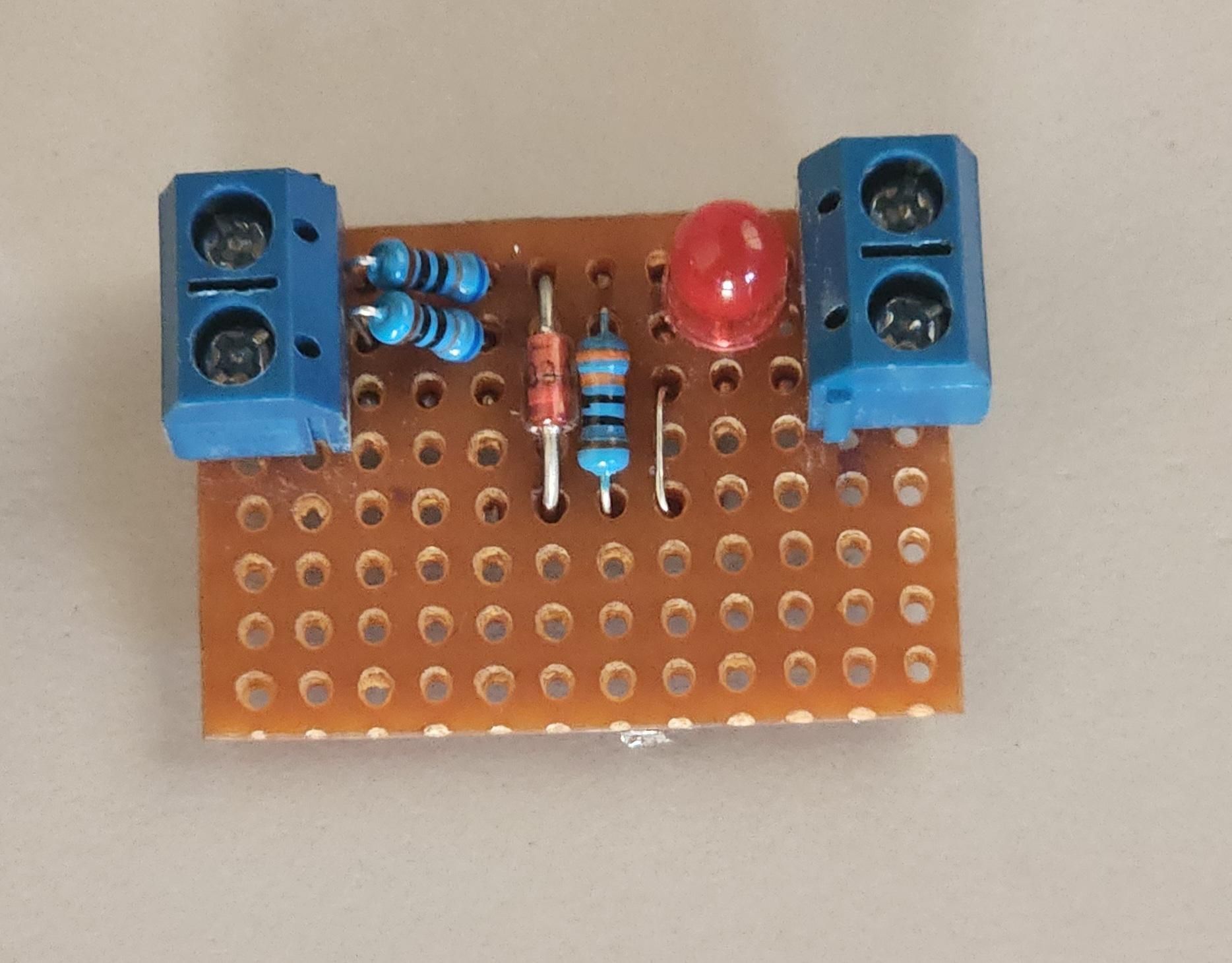
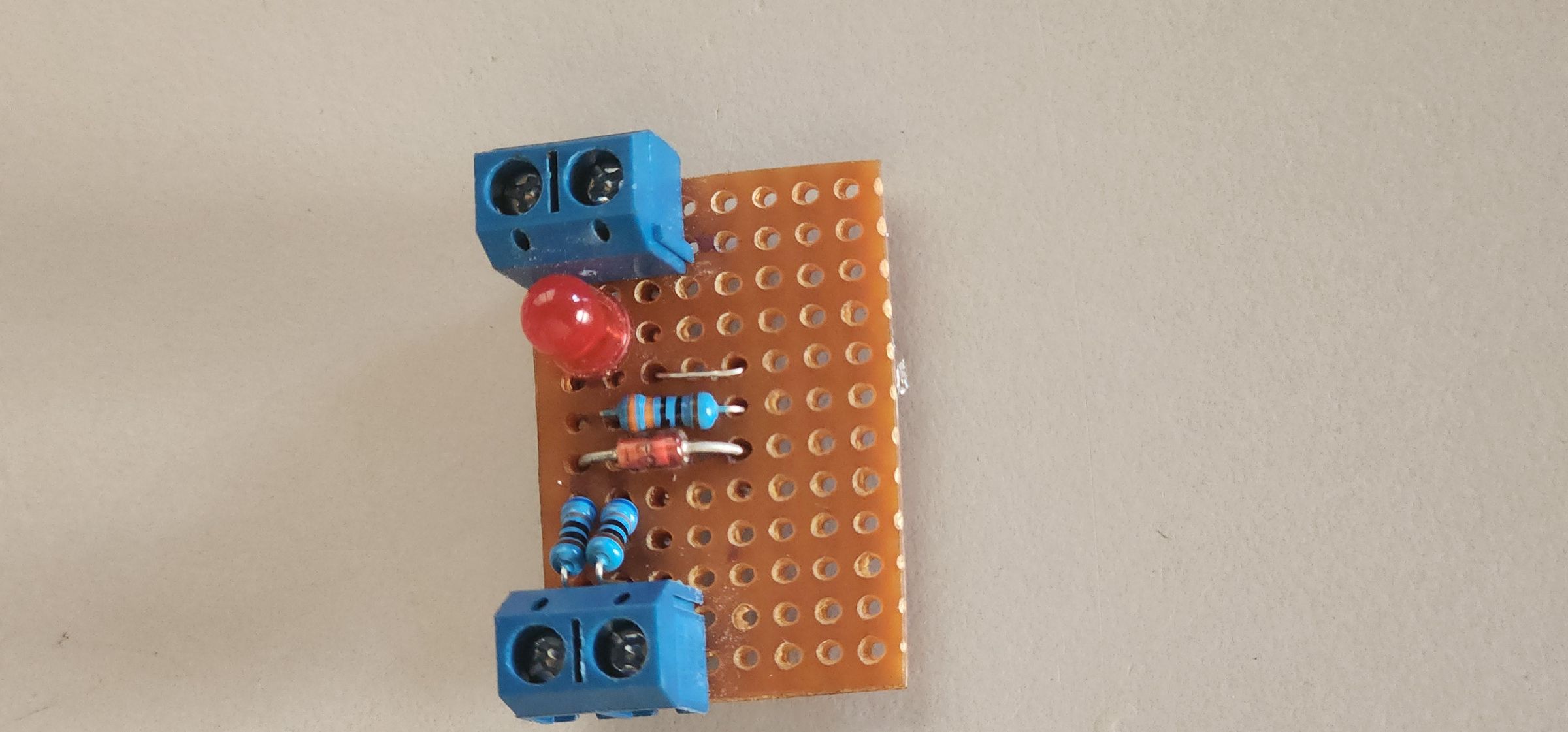
Now that we have completed the design and selected the components, let's build the Zener voltage stabilizer.
The final circuit uses:
- 15 V DC input source
- 330 Ω / 0.5 W series resistor
- 5.1 V / 0.25 W Zener diode
- Load drawing up to 20 mA
- Optional output capacitor
Test the Stabilizer
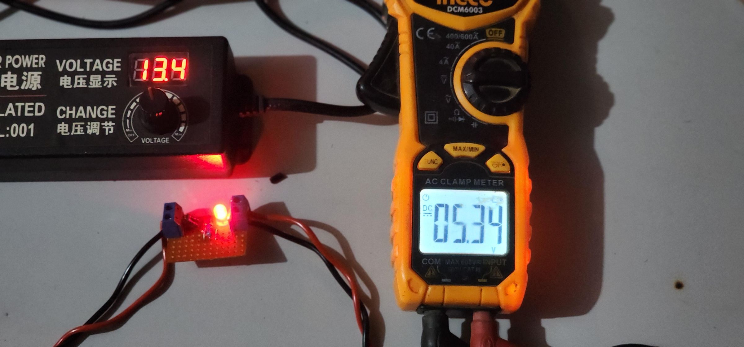
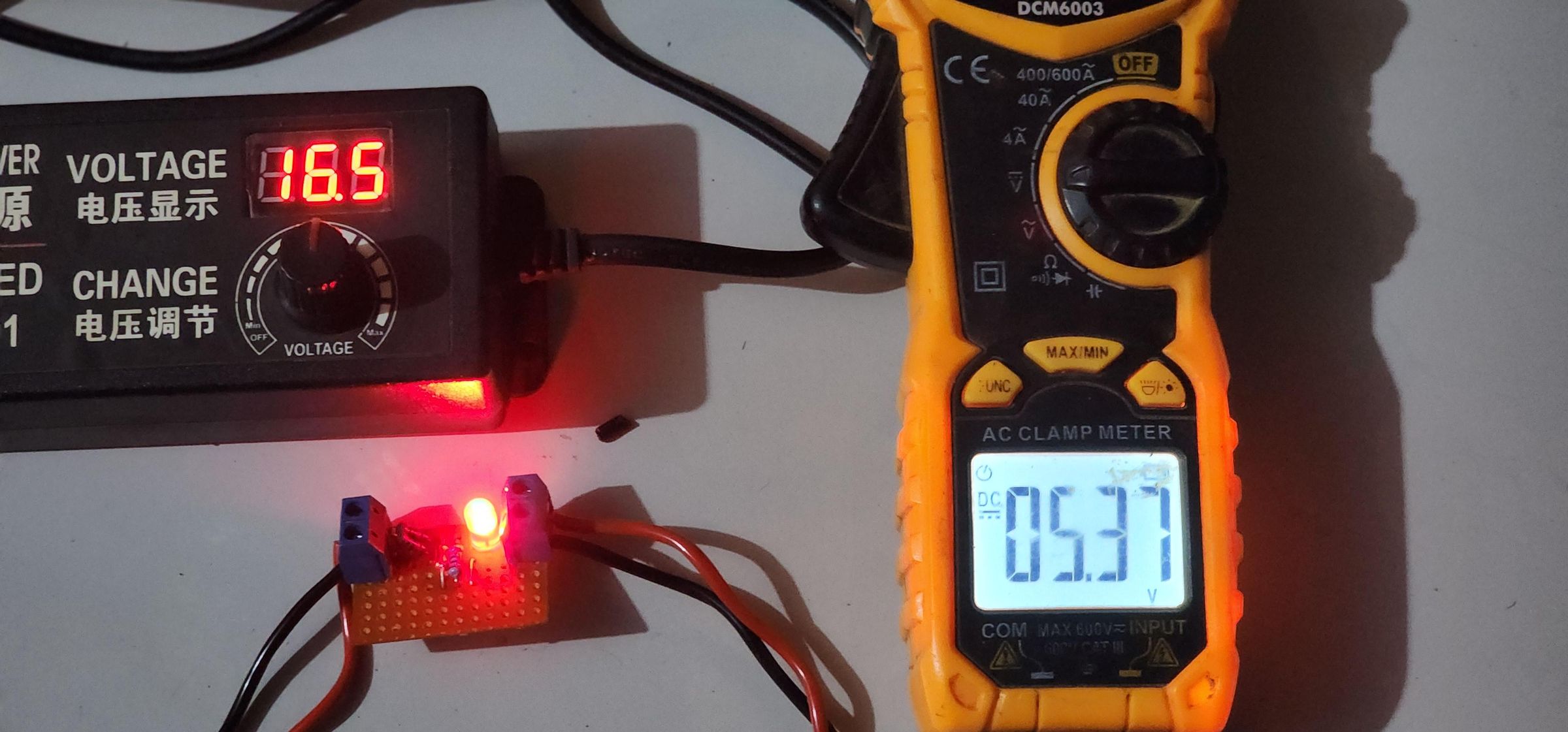
The circuit is now assembled. It's time to verify whether the Zener voltage regulator behaves as expected.
The purpose of this test is to compare the theoretical design with the actual behavior of the circuit.
Test 1: At Minimum Input Voltage (13.5 V)
For this test, our test load is a red LED that consumes approximately 10 mA.
We set the input voltage to Vin(min) = 13.5 V.
The output voltage remains very close to the expected 5 V.
Test 2: At Maximum Input Voltage (16.5 V)
We gradually increase the input voltage up to Vin(max) = 16.5 V.
The output voltage increases slightly. This is expected because the Zener voltage is not perfectly constant and varies slightly with the current flowing through the diode. This behavior is related to the Zener diode's dynamic resistance and its voltage-current characteristics.
Nevertheless, Vout remains very close to 5 V, confirming that the circuit provides the expected voltage stabilization over the specified input voltage range.