Desktop Calendar

This project is a simple recreation of cardboard-flip desktop calendars. The project is added with a real time clock and a daily task note. Users can log up to 3 task with 25 characters each. The project uses the gen4-uLCD-70DCT-CLB display which perfect for large text input/output projects.
How It Works

The day and time of the calendar is automatically run by the system, you can also add task in the calendar.
Components

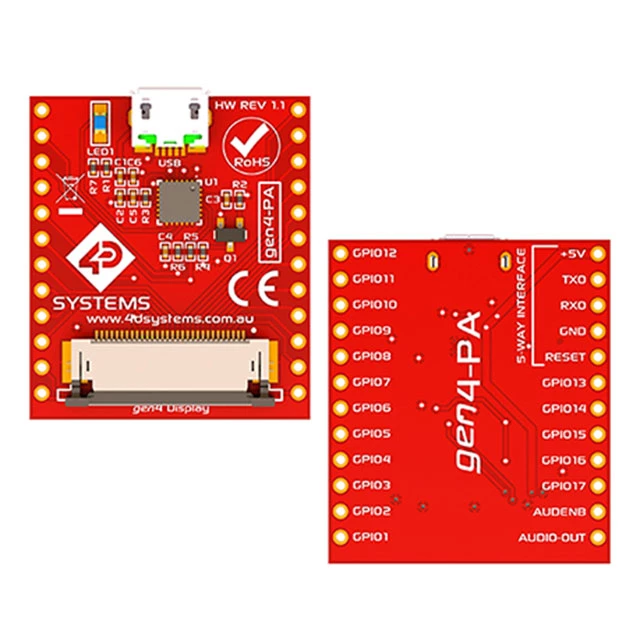


- gen4-uLCD70DCT-CLB
- gen4-PA
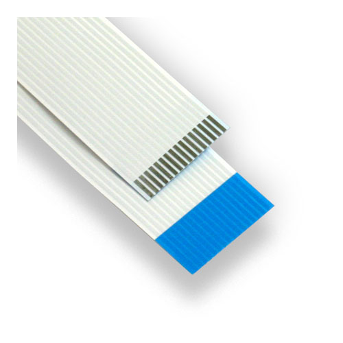
- FFC Cable
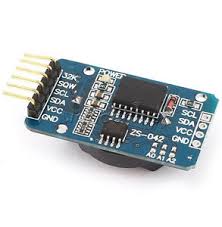
- ZS-042 Real Time Clock
- microSD Card
- microUSB Cable
Build


Build the circuit as shown in the diagram.
Download the project file here.
Open the project using Workshop 4. This project uses the Visi Environment.You can modify the properties of each widget. Download the project file here.You can download Workshop 4 IDE and the complete code for this project from our website.Open the project using Workshop 4. This project uses the ViSi Environment.You can modify the properties of each widget. (See Image 2)
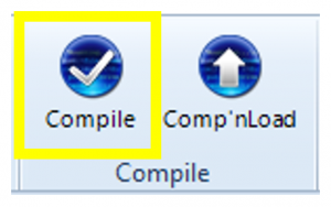
Click on the Compile button. (This step could be skipped. However, compiling is essential for debugging purposes.) (Shown in Image 3)
Connect the display to the PC using μUSB-PA5 and a mini USB cable. Make sure that you are connected to the right port. Red Button indicates that the device is not connected, Blue Button indicates that the device is connected to the right port. (See Image 4)
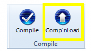
Now click on the “Comp’nLoad” button. (Shown in Image 5)
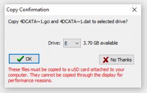
Workshop 4 will prompt you to select a drive to copy the image files to a μSD Card. After selecting the correct drive, click OK. (Shown in Image 6)
Demonstration


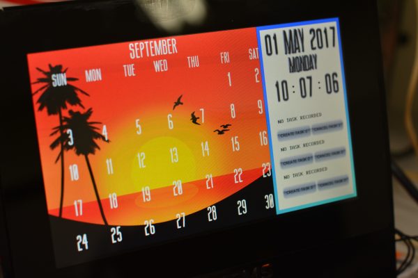

The module will prompt you to insert the μSD card. (Shown in Image 1)
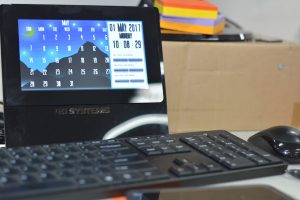
Properly unmount the μSD Card from the PC and insert it to the μSD Card slot of the display module. The image below must appear on your display after completing the steps above.