Differential Swerve Drive
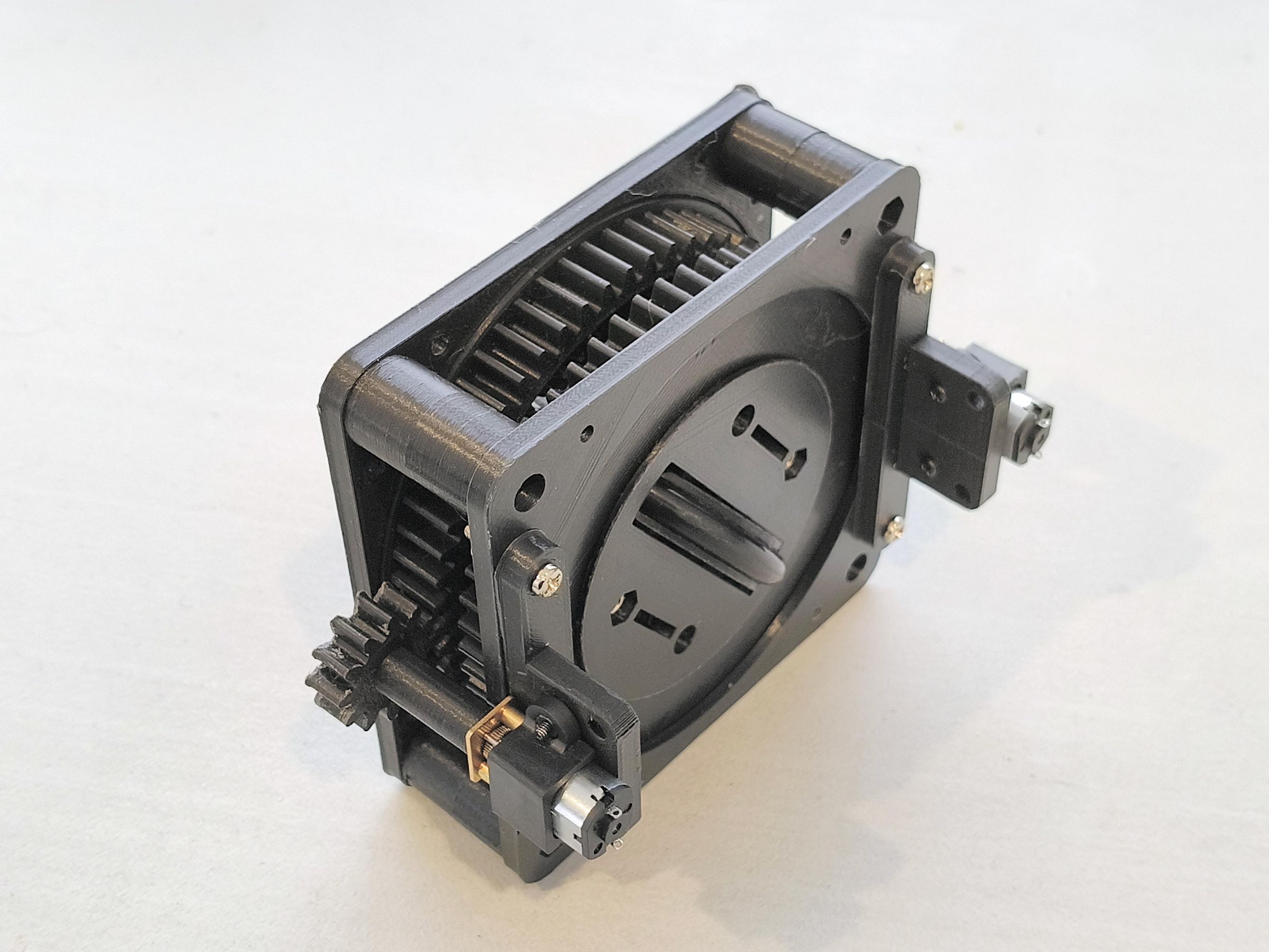
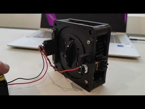
Imagine a car that can move sideways when parallel parking.
This instructable explains how to make a differential swerve drive which makes this possible.
All gears and wheels are 3D printed. The design is such that metal bearings are not required for light loads such as a model car or plotter.
The only components you need for each swerve drive are:
- a rubber O-ring for the tyre
- two 6 volt N20 geared motors for drive and steering and
- two N20 micro motor mounting kits
- a few nuts and bolts
A feature of this drive is that both motors are fixed to the chassis which means there are no wires to tangle if the wheels are rotated beyond 360 degrees.
The estimated cost per drive is less than $20
Supplies
The following components were purchased from https://www.aliexpress.com/
For each swerve drive you need:
- 2 only 6 volt 60 RPM N20 geared motors with encoders [1]
- 2 only N20 Micro Mounting Kits.
- 1 only OD56 mm diameter O-ring.
The following components were purchased locally:
For each swerve drive you need:
- 9 only M3 x 25mm bolts.
- 1 only M3 x 20mm bolt.
- 10 only M3 nuts.
For testing you will need:
- Four only 1.5 volt AA batteries.
- 1 only four-cell battery holder.
- Some hookup wire and clips for testing.
Notes
[1]
The encoders are optional if you only want coarse control such as switches.
If you plan on using a microcontroller you will also need the following items for each drive:
- 1 only TB6612FNG motor controller.
- 1 only 6mm diameter x 3mm neodymium magnet for auto-centering.
- 1 only A3144 Hall effect transistor.
Theory
Drives that allow (robot) movement in any direction while maintaining body orientation have always fascinated me. There are several types:
- Mecanum
- Omni Wheel
- Swerve
- Differential Swerve
Mecanum and Omni wheels spin on a single, fixed axis. Instead of turning the whole wheel, you change the speed of individual motors. The robot moves, on angled rollers attached to the wheel rims, in the direction of the combined forces (vector sum).
Swerve drives, unlike Mecanum or Omni wheels, use standard wheels that can rotate 360 degrees to face any direction. Each wheel has two independent motors: one to spin the wheel for power, and one to steer the wheel's orientation. The final direction is achieved by physically pointing all wheels towardswhere you want to go.
The chassis orientaion remains fixed if all wheels point the same way and move in unison. The chassis can be made to rotate if all wheels are angled to form a circle.
A differential swerve drive achieves the same 360-degree steering as a standard swerve, but it uses a completely different motor setup to maximize power.
Instead of using one motor for driving and one for steering, a differential swerve uses two motors linked to the wheel through a differential gear system. When both motors spin in the same direction, the wheel module steers. When they spin in opposite directions, the wheel drives forward / reverse.
By blending the motor outputs, a differential swerve can channel 100% of the power from both motors into driving when moving in a straight line whereas standard swerve drives can only ever use their single drive motor for pushing power.
STL Files
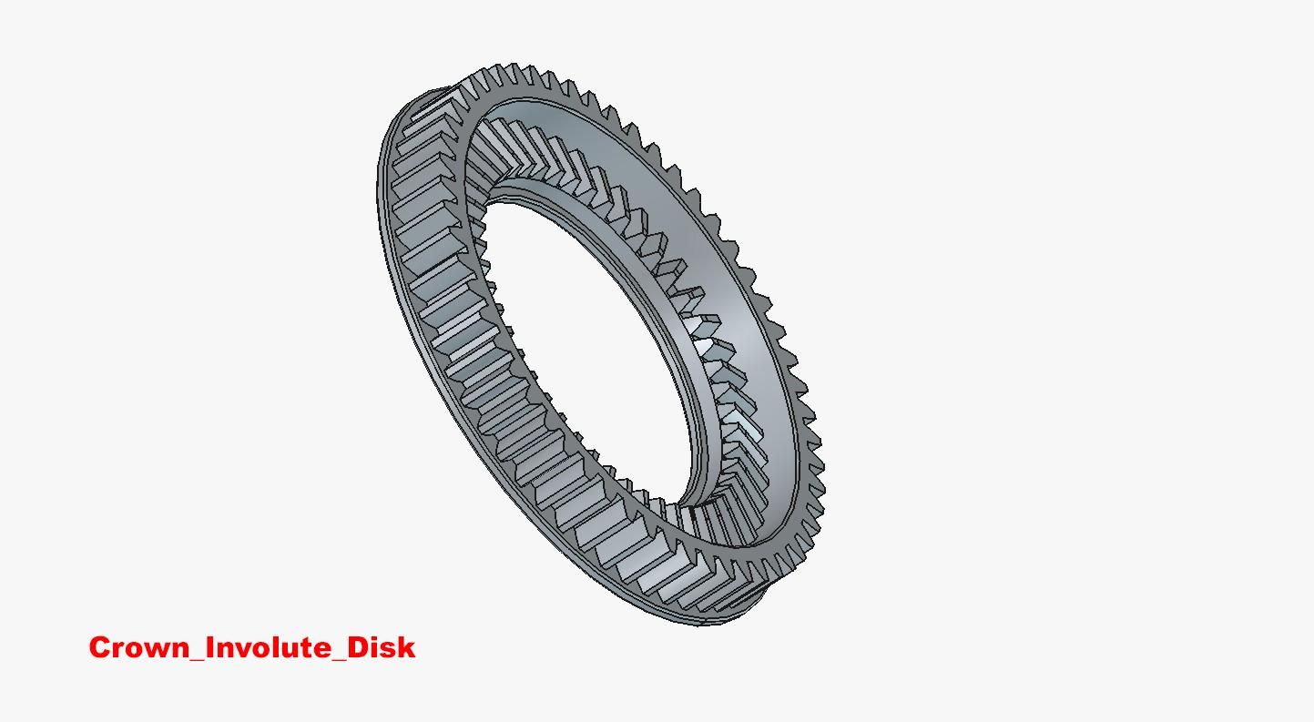
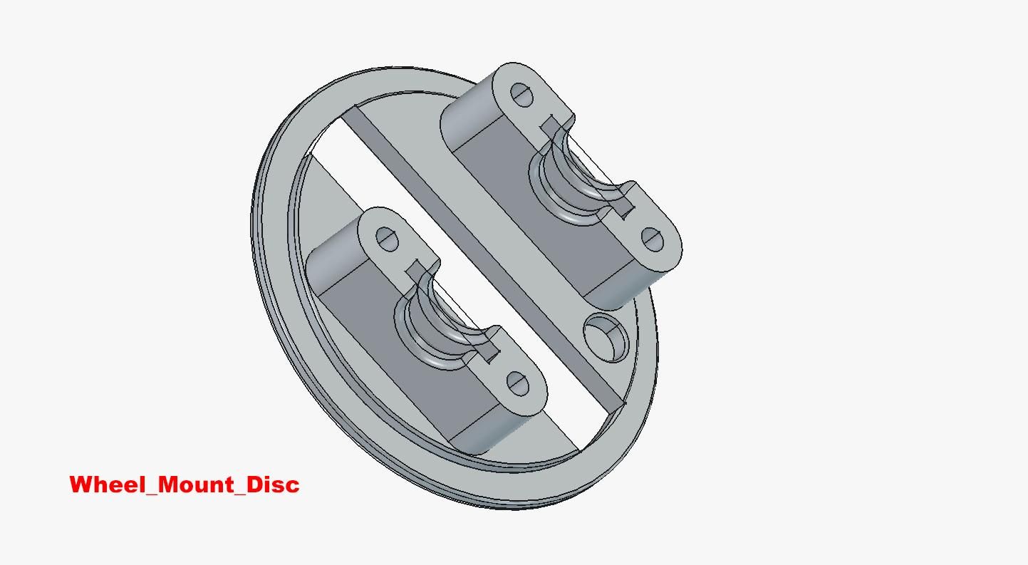
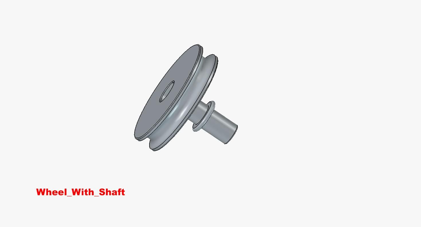
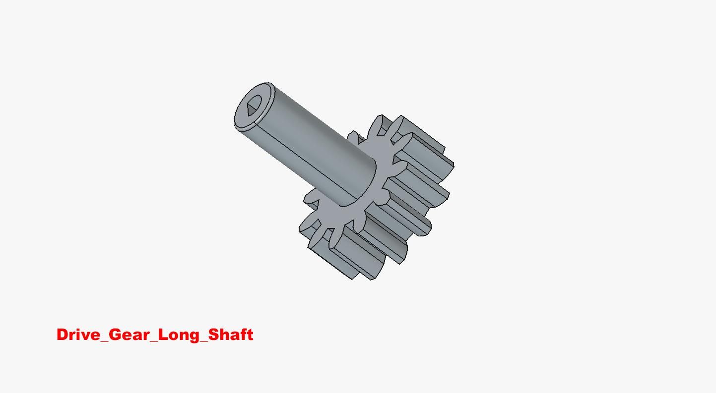
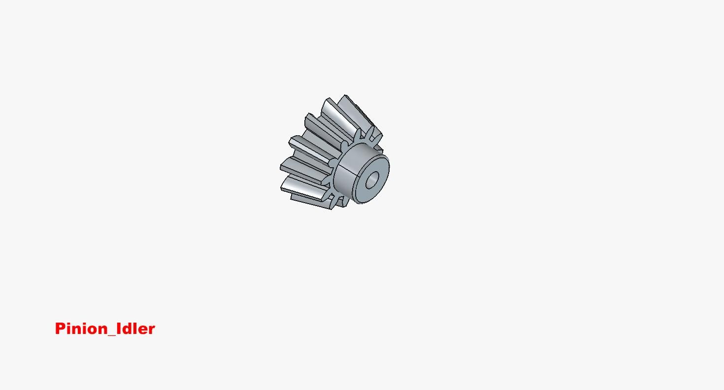
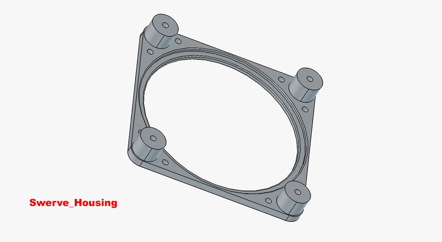
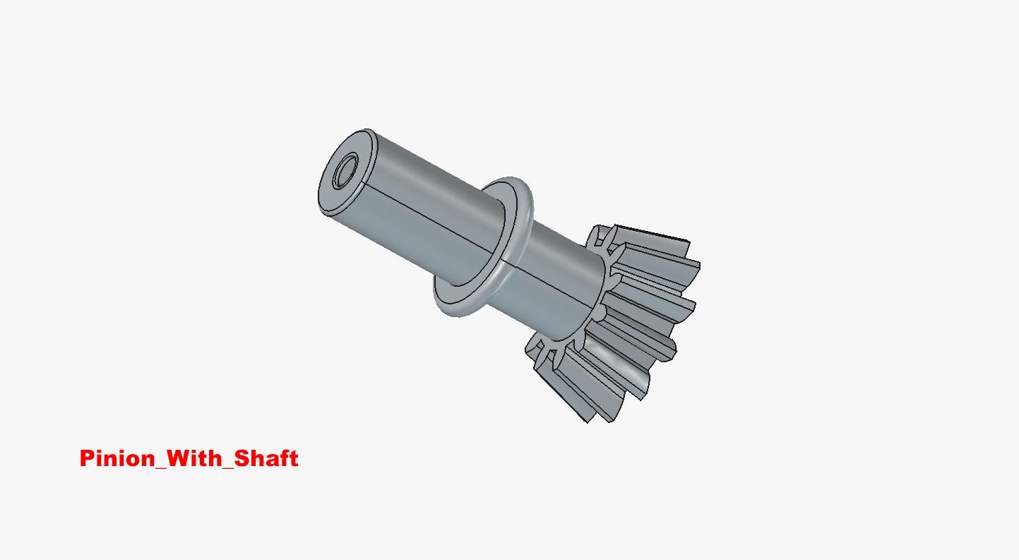
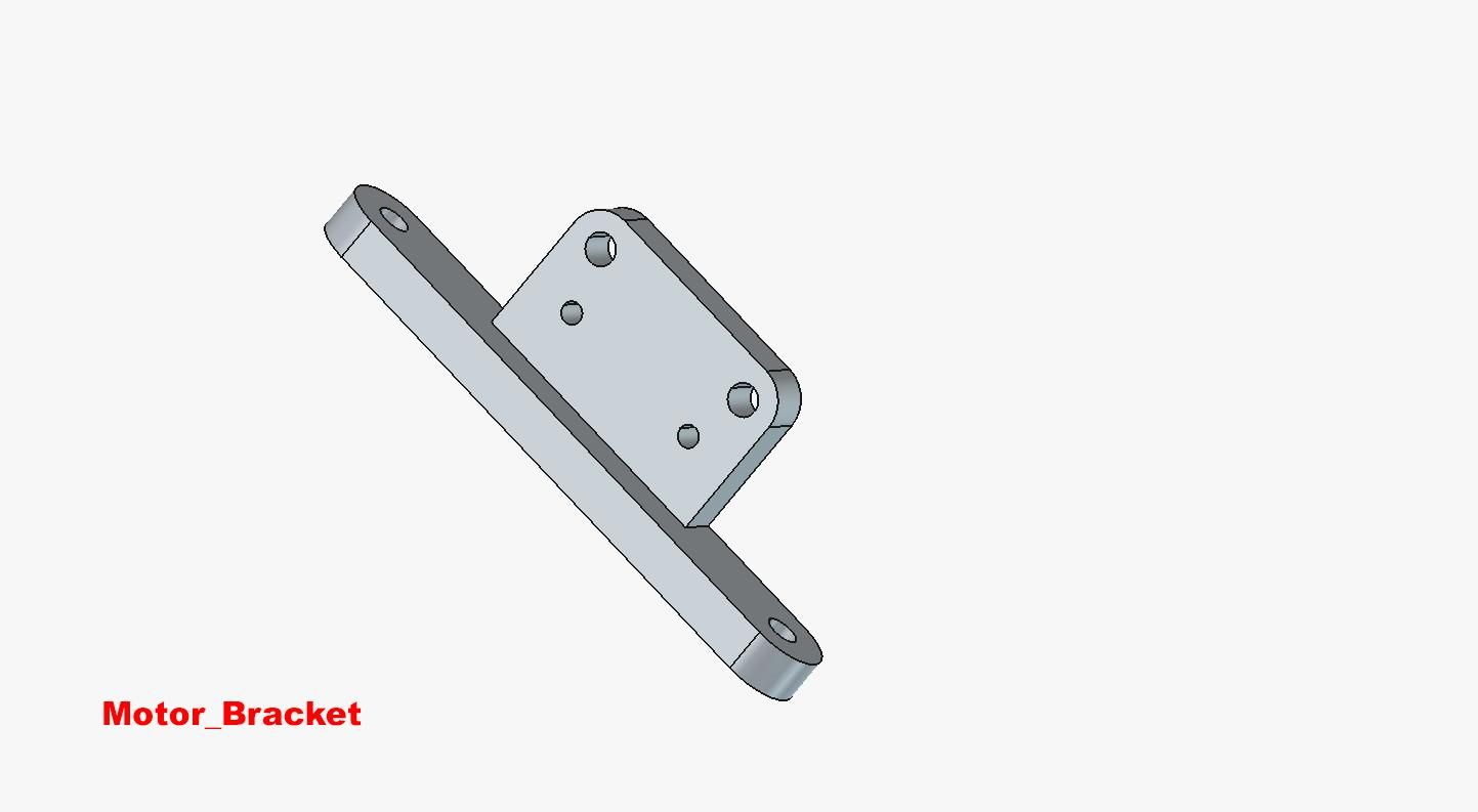
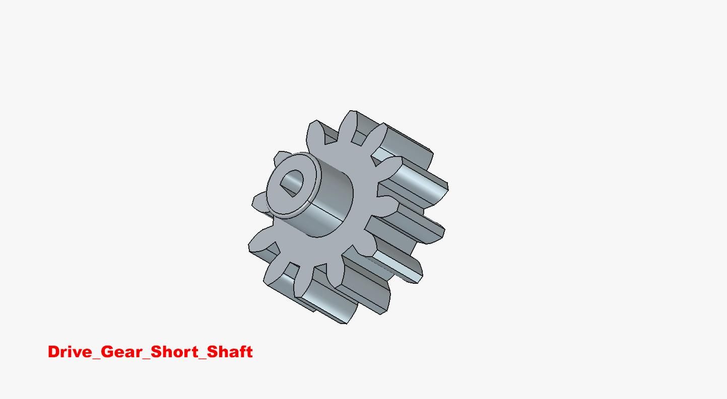
The following 3D parts are required:
- 2 only Crown_Involute_Disc
- 2 only Wheel_Mount_Disc
- 2 only Swerve_Housing
- 2 only Motor Bracket
- 1 only Wheel_With_Shaft
- 1 only Pinion_With_Shaft
- 1 only Pinion_Idler
- 1 only Drive_Gear_Long_Shaft
- 1 only Drive_Gear_Short_Shaft
When assembled the above parts create a cage-within-a-cage.
The inner-most cage, which holds the wheel and differential gears, is free to rotate 360 degrees within the outer Swerve_Housing.
STL files for each of the above parts are attached
Al parts were printed on a Voxelab Aquila 3D printer using 1.75 mm PLA, a 0.4 mm nozzle, and 0.2 mm layer height.
Assembly details follow.
Swerve Drive Assembly
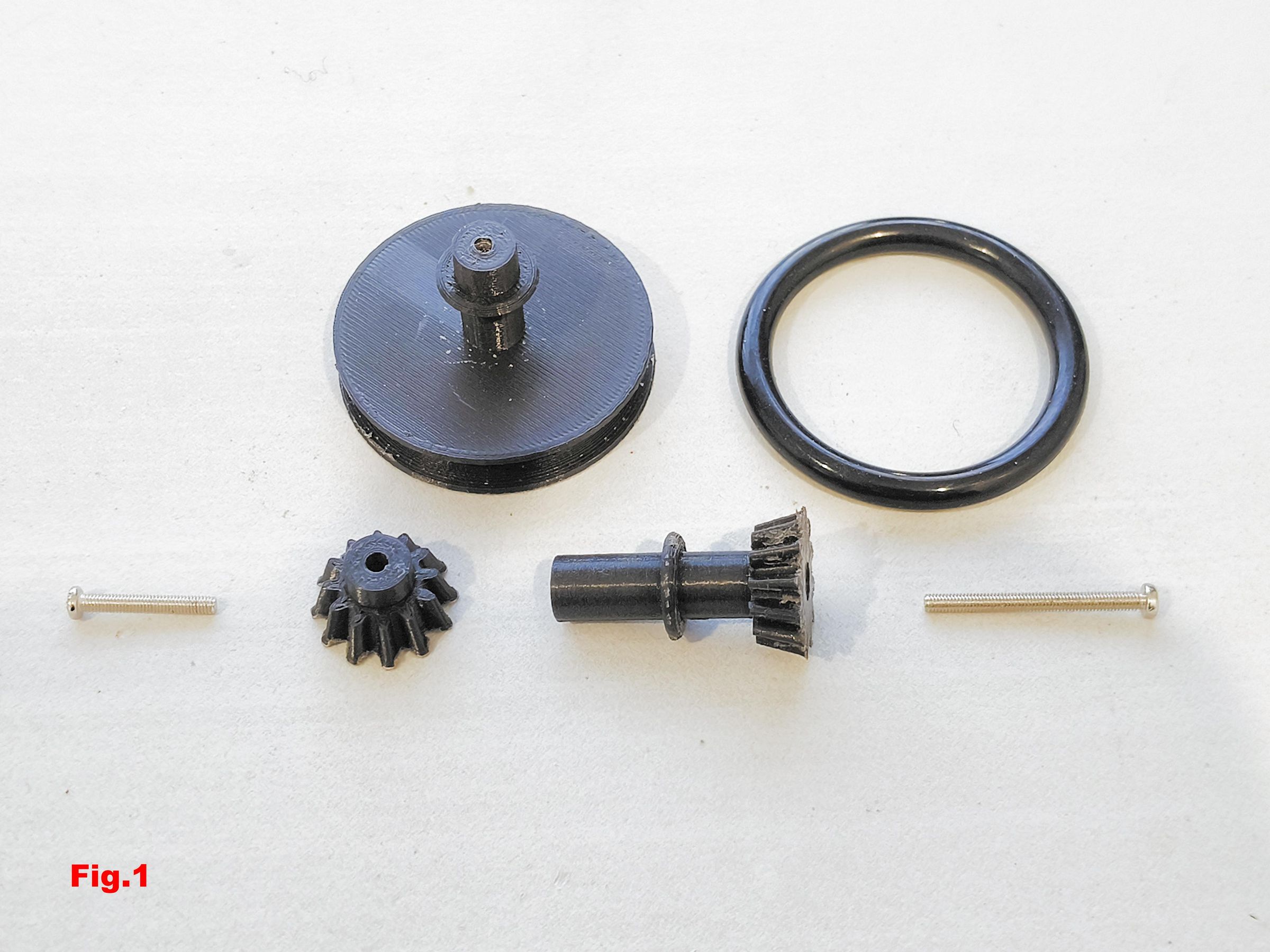
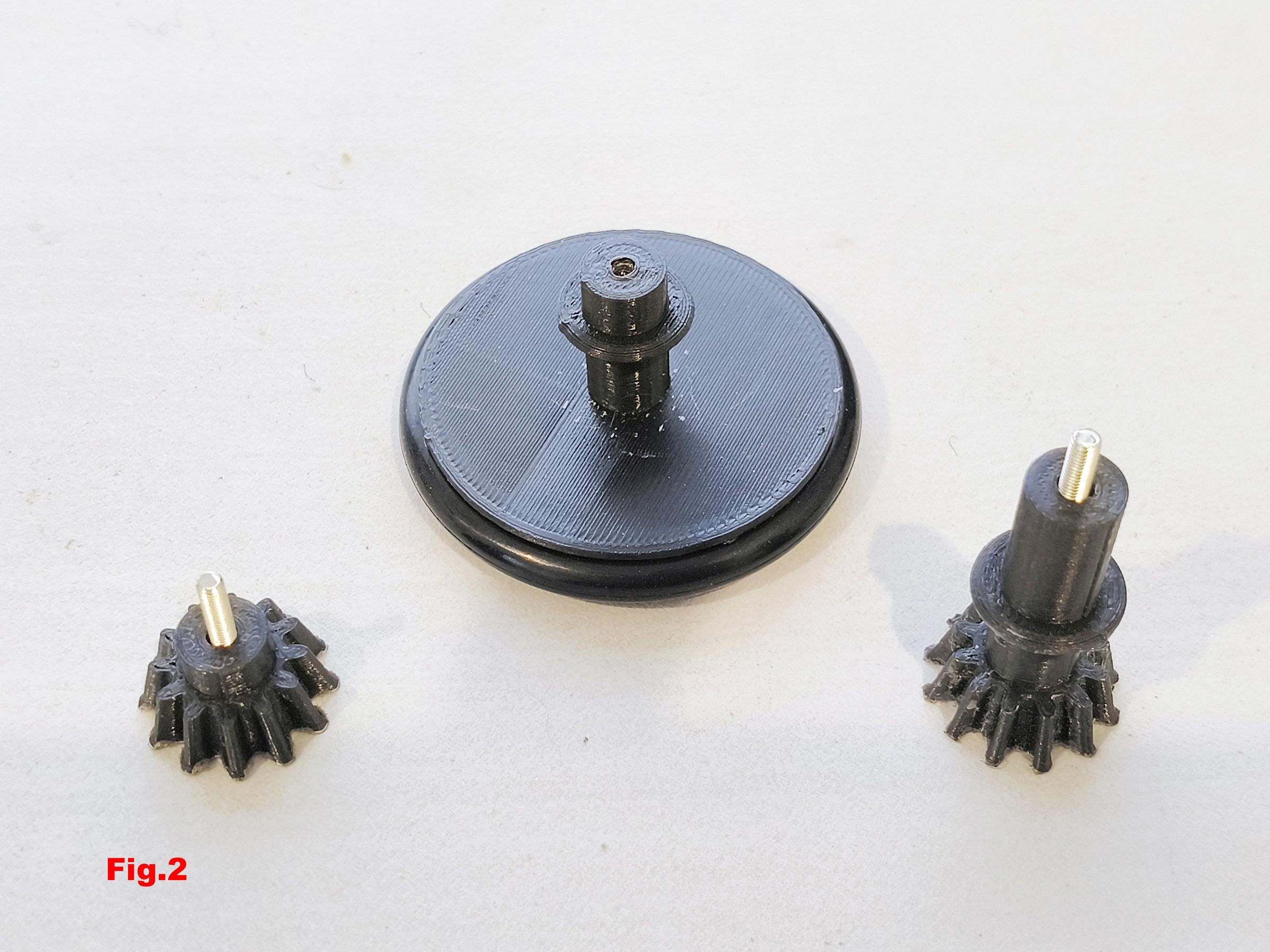
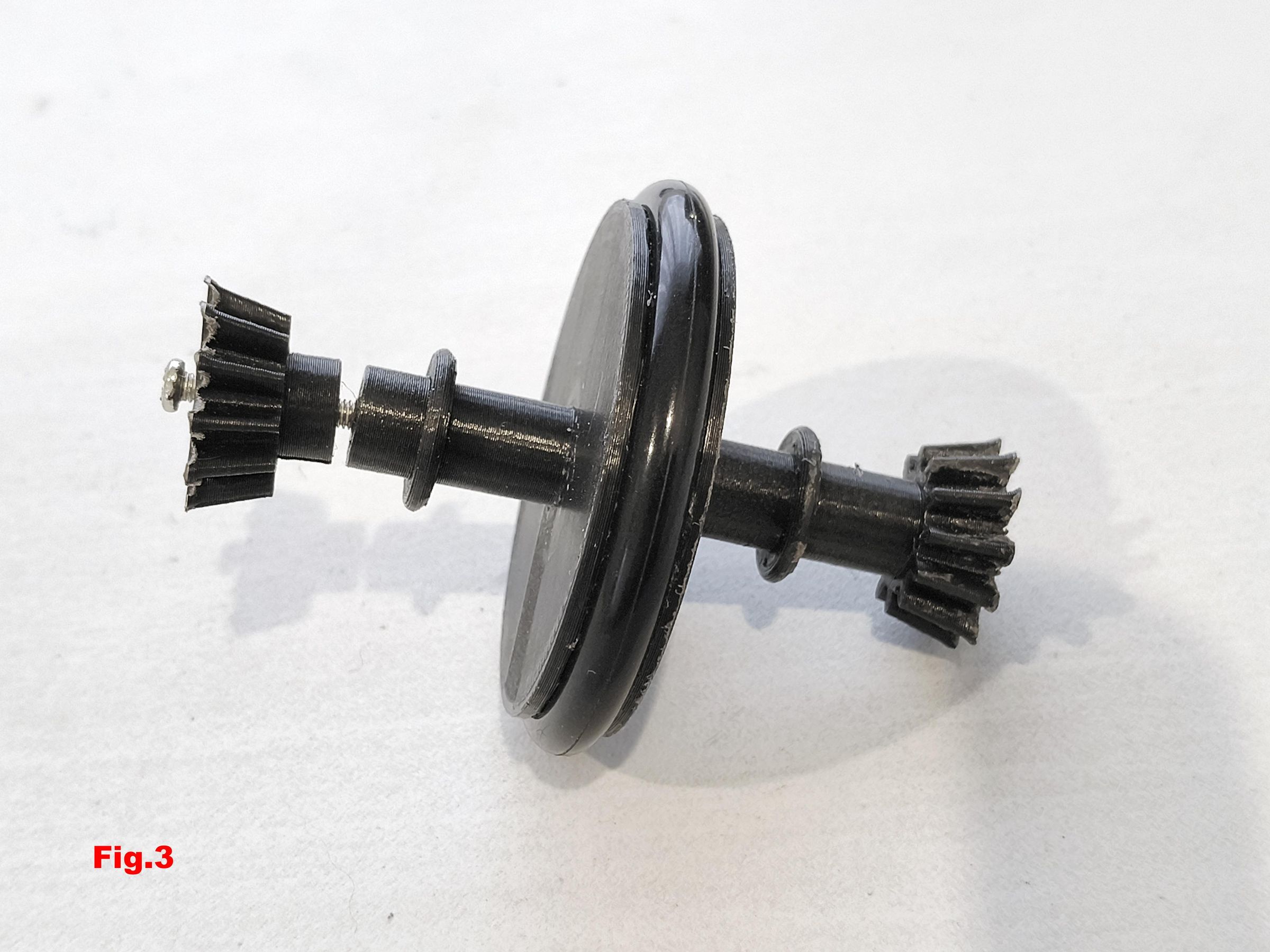
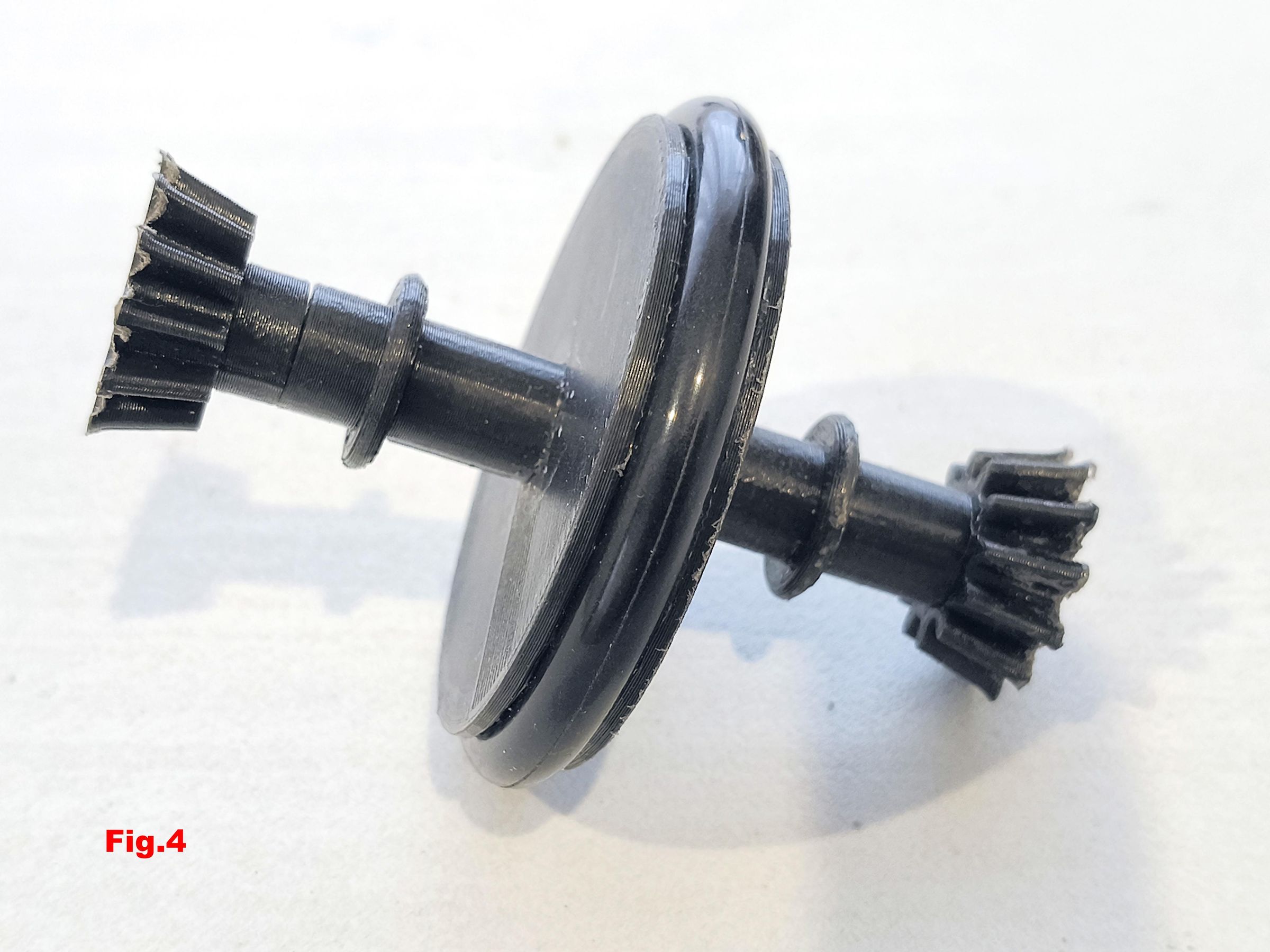
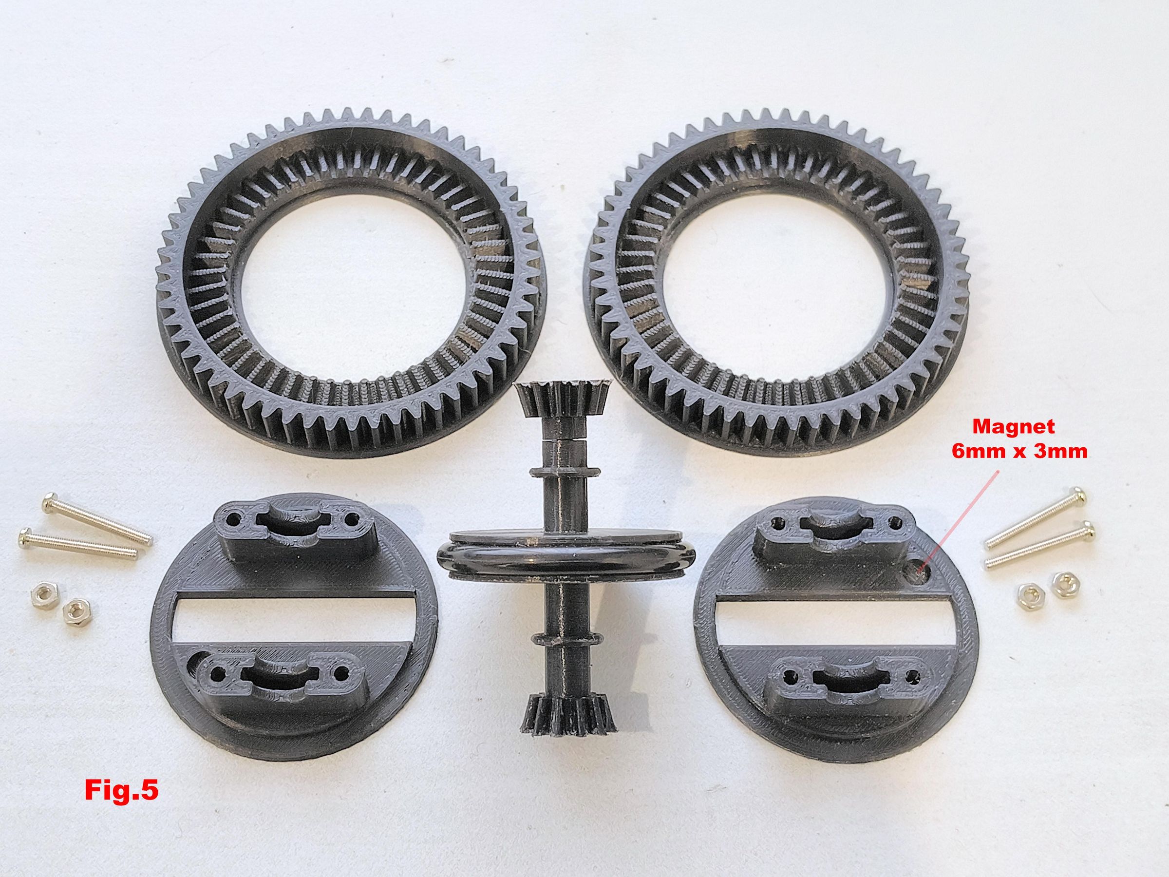
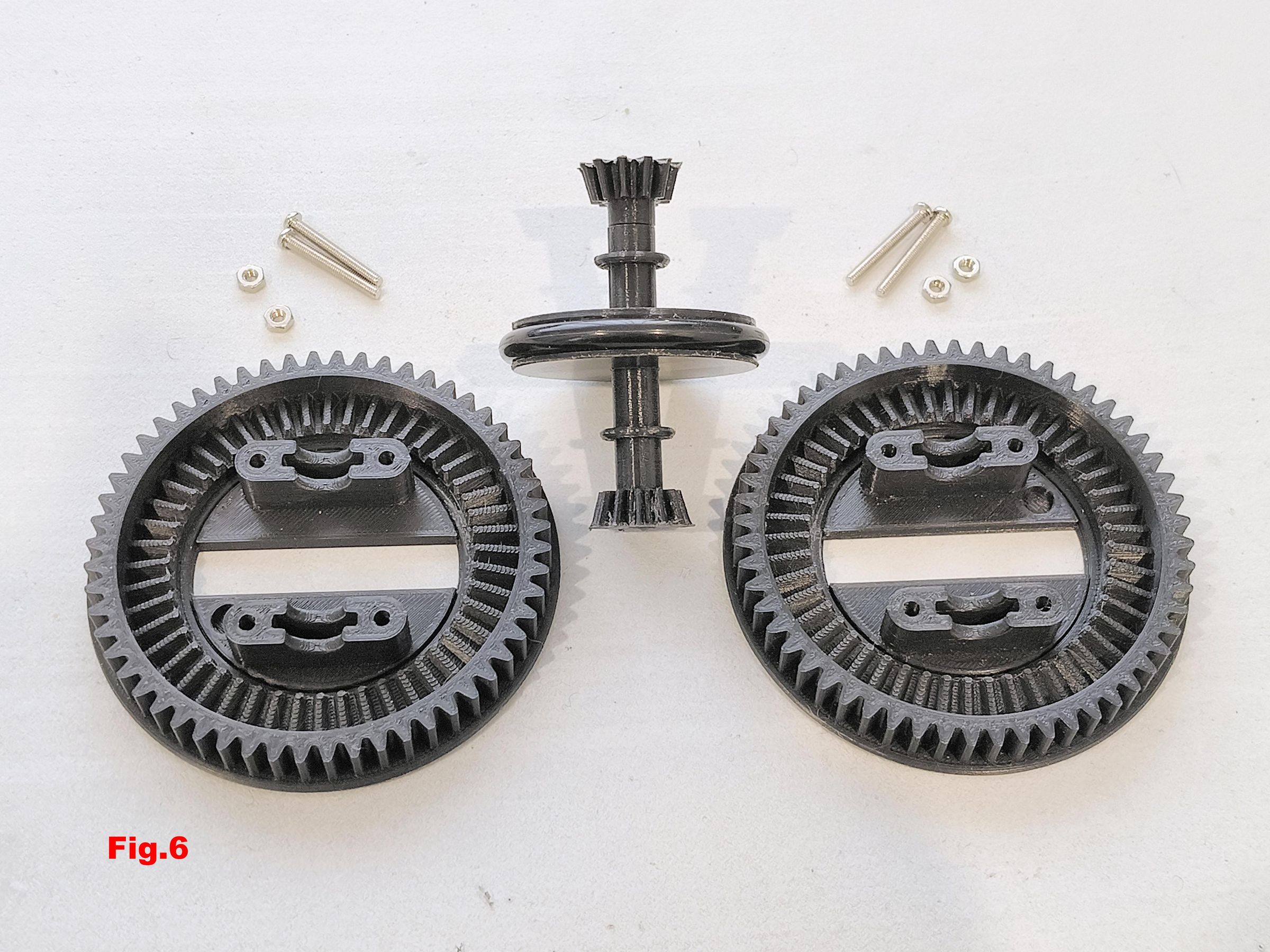
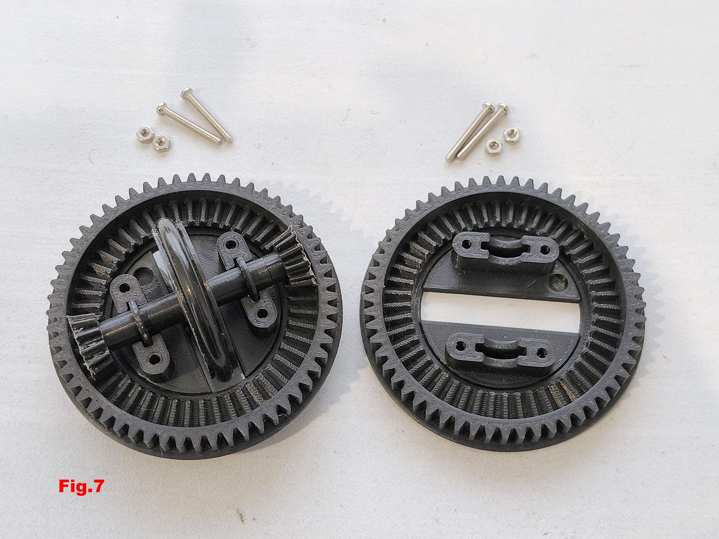
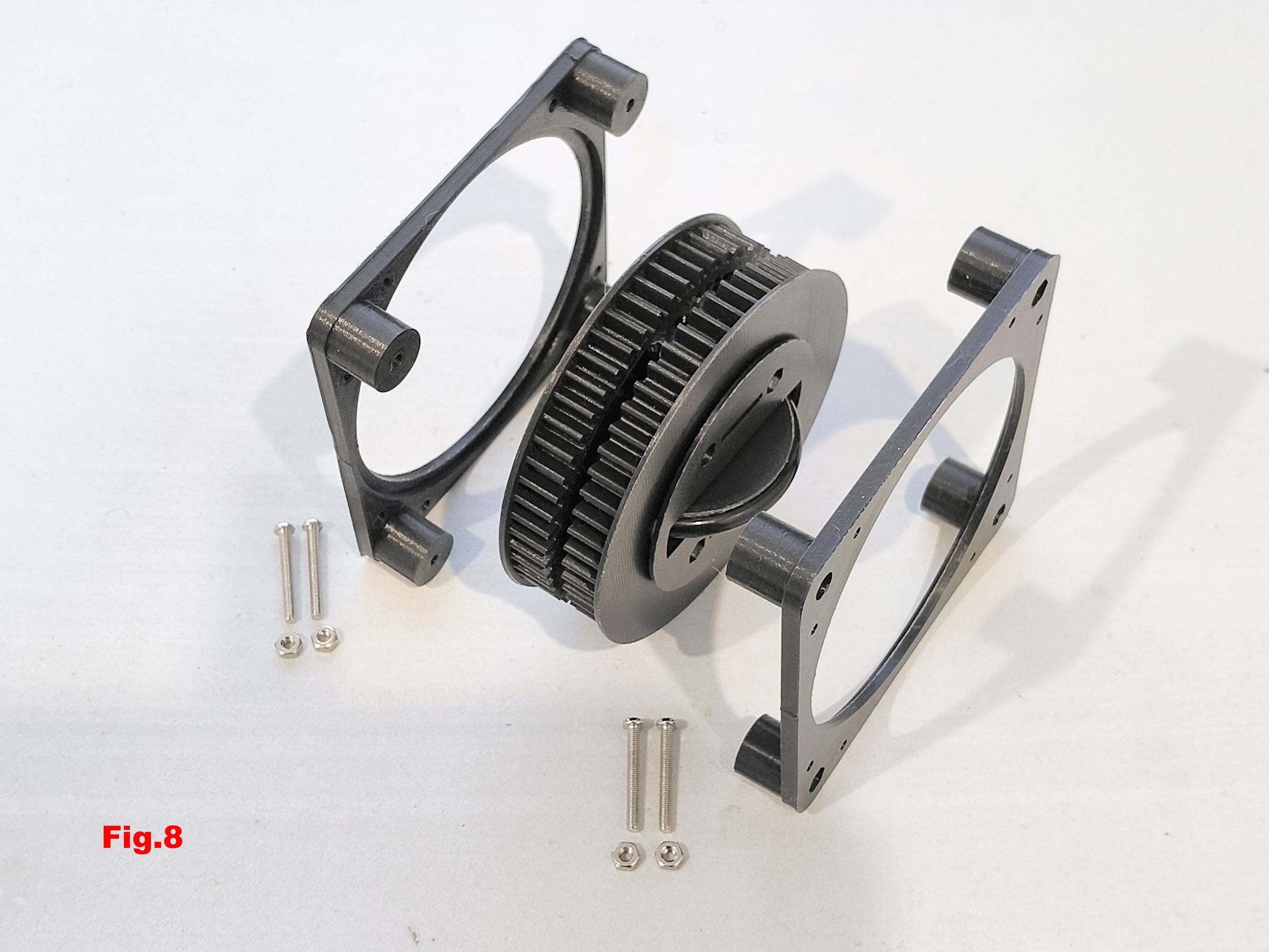
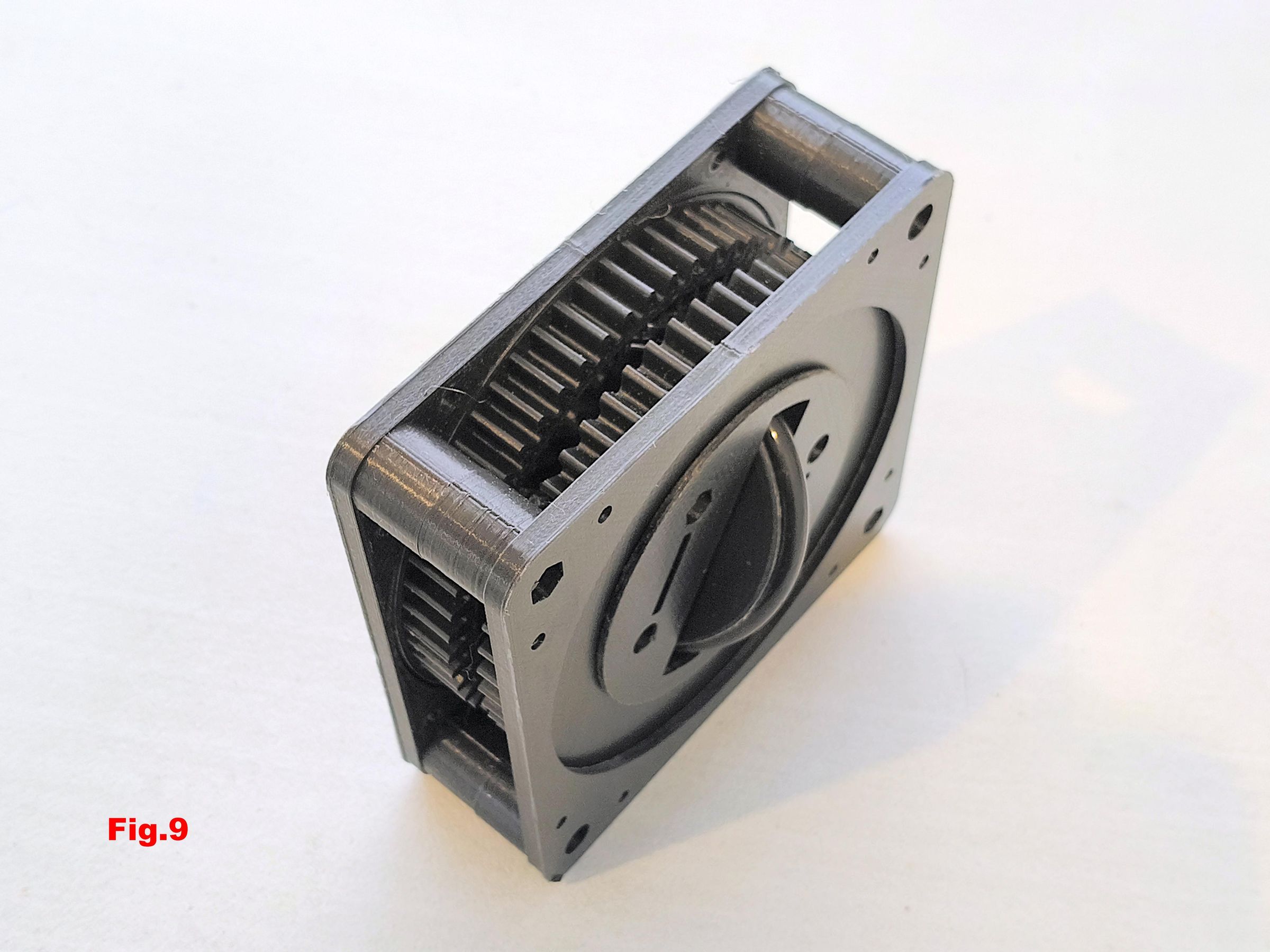
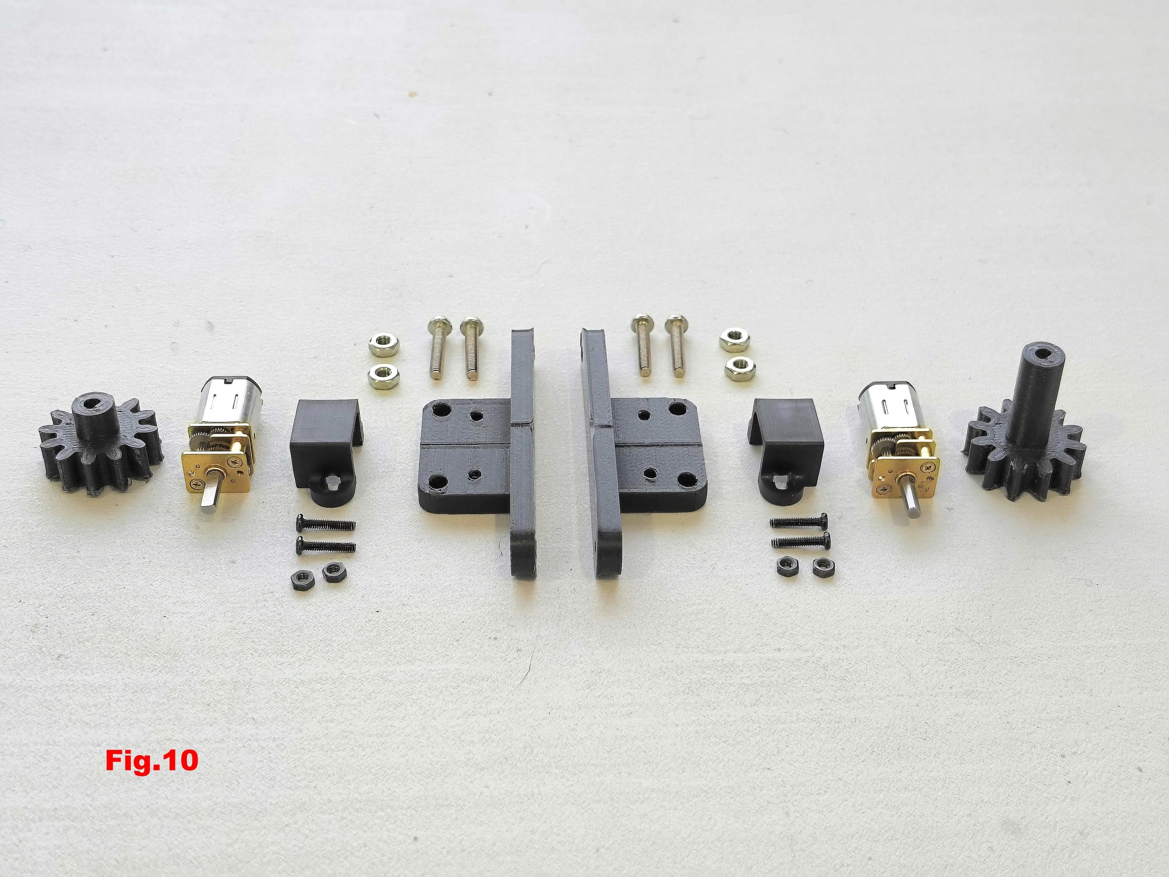
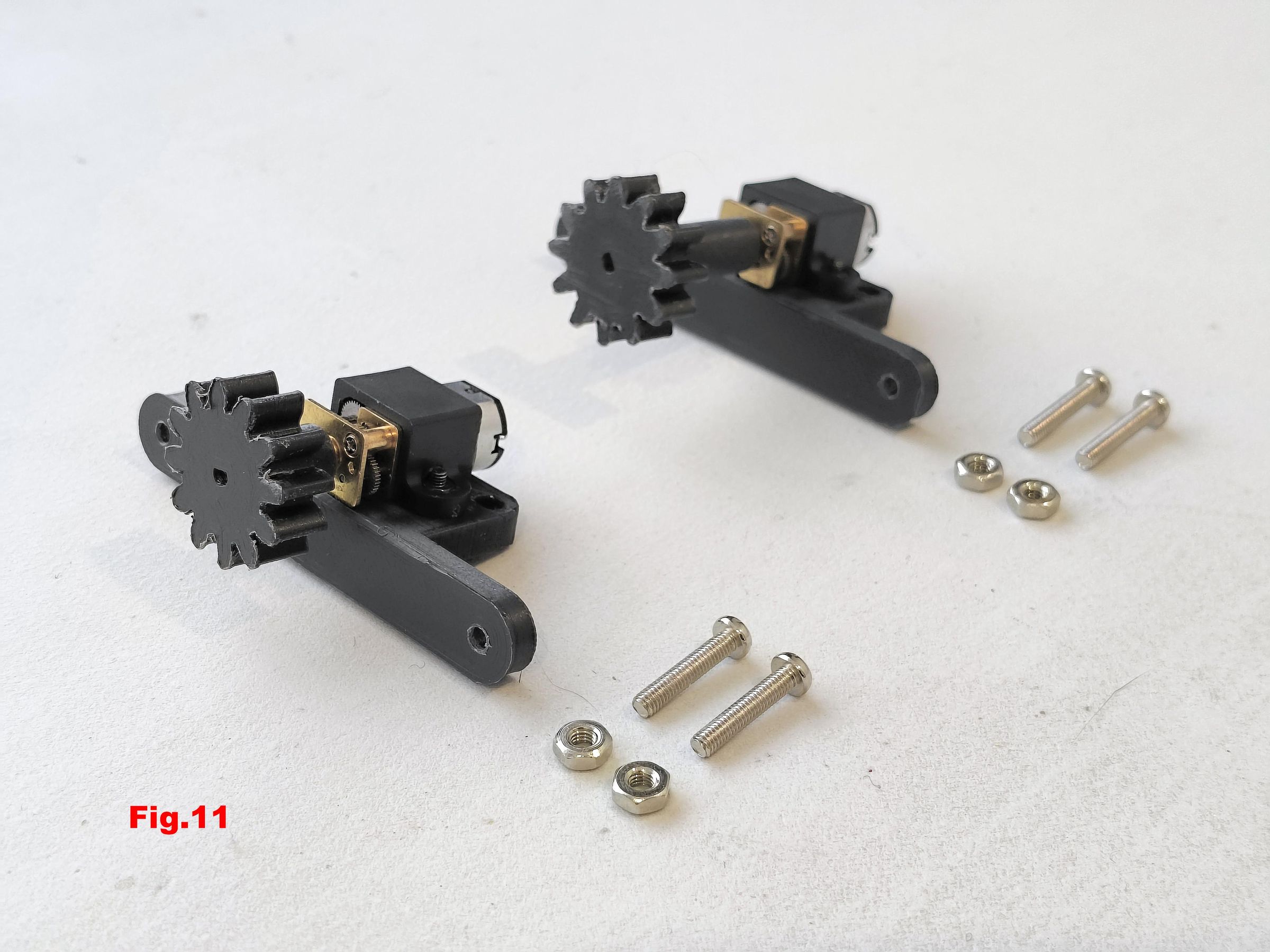
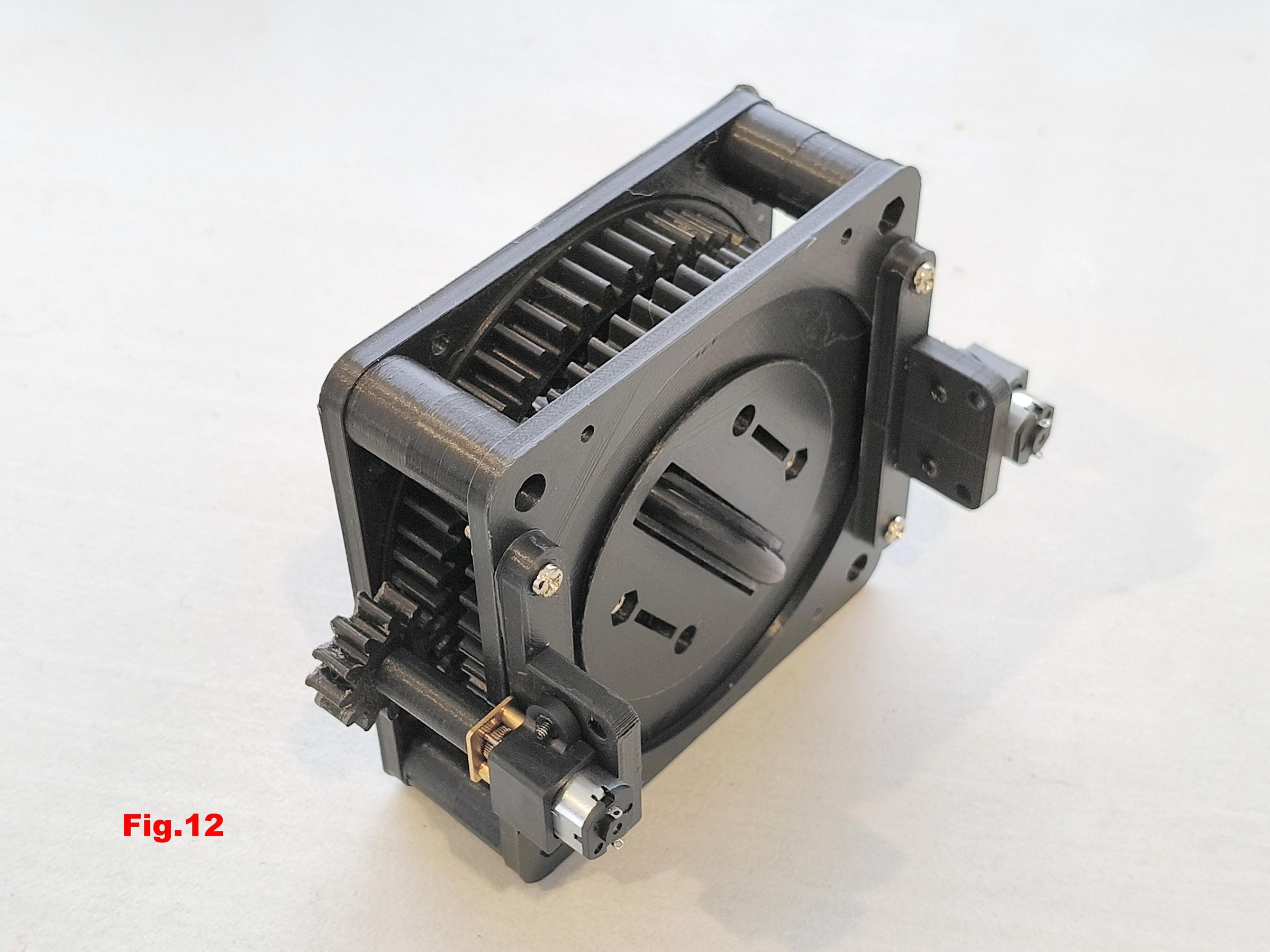
To assemble simply follow fig.1 through Fig.12.
The bolts in fig.1 and fig.2 are M3 x 20 mm and M3 x 30 mm
The nuts and bolts in fig.7 and fig.8 are M3 x 25 mm
The Pinion_With_Shaft in fig.3 and fig.4 is firmly attached to the wheel. The idler pinion must freely spin.
A 6 mm x 3mm wheel-alignment magnet can optionally be glued into the indent shown in Fig.5
The N20 geared motors with encoders can be substituted for the N20 motors shown in fig.12
Each drive has four mounting holes for attaching it to a chassis.
Summary
All gears and wheels are 3D printed. The design is such that metal bearings are not required for light loads such as a model car or plotter.
The only components you need for each swerve drive are:
- a rubber O-ring for the tyre
- two 6 volt N20 geared motors for drive and steering and
- two N20 micro motor mounting kits
- a few nuts and bolts
A feature of this drive is that both motors are fixed to the chassis which means there are no wires to tangle if the wheels are rotated beyond 360 degrees.
Additional features include:
- The chassis orientation remains fixed if all wheels are driven in unison
- Each drive has provision for a 6mm x 3mm wheel alignment magnet should you wish to use N20 motors with encoders.
The estimated cost per drive is less than $20
Click here to view my other instructables.