Diy Re-Configurable Wifi Button With Charging Base V2
by The Young Maker in Circuits > Electronics
2145 Views, 19 Favorites, 0 Comments
Diy Re-Configurable Wifi Button With Charging Base V2


Welcome to this step-by-step guide on creating your very own ESP01S-based tiny WiFi button! This nifty little device will enable you to trigger a variety of actions and control multiple devices with a simple press of a button. Whether you want to turn on the lights, play your favorite playlist, or even lock the front door, this customizable button has got you covered.
By utilizing the power of the ESP01S module, which is a compact WiFi-enabled microcontroller, you can connect your button to your home network and leverage its wireless capabilities. With some basic programming and a few components, you'll have a versatile WiFi button that can be integrated into your smart home system or used as a standalone device.
So, grab your soldering iron, gather the necessary components, and let's get started on building your very own ESP01S-based tiny WiFi button. Get ready to experience the convenience and control at your fingertips!
Supplies


Material used for the wifi button :
- An ESP-01 or ESP-01S (In my case , I have an ESP-01S)
- A 40mAh or similar Li-Po Battery (I took mine from an old electronics but this one also work )
- 2 custom PCBs (The Gerber files can be found on my Github)
- A 3D printed case (The 3D files can be found on my Github)
- A small pushbutton (I took mine from here)
- Some copper wire
- A Linear Voltage Regulator (I took mine from here)
Material used for the charging base :
- A small charging module (I took mine from here)
- 2 other custom PCBs (The Gerber files can be found on my Github)
- A 3D printed case and its base (The 3D files can be found on my Github)
- 3 small connector (I used these but you can take the ones that you prefer)
- Some copper wire
- A small pushbutton (I took mine from here)
Total list of necessary components
- 1 ESP-01 or ESP-01S
- 1 40mAh or similar Li-Po Battery
- 2 small pushbutton
- 3 small connector
- 1 small charging module
- The 4 PCBs
- The 3d printed parts
- 1 Linear Voltage Regulator
Order the PCBs


Each PCB need to have a different thickness to work properly.
- The PCB 1 have a thickness of 0.8mm
- The PCB 2 have a thickness of 1.6mm
- The PCB 3 have a thickness of 0.6mm
- The PCB 4 have a thickness of 1.6mm
Be sure to order the right thickness for each PCBs or it will not work !
Programming

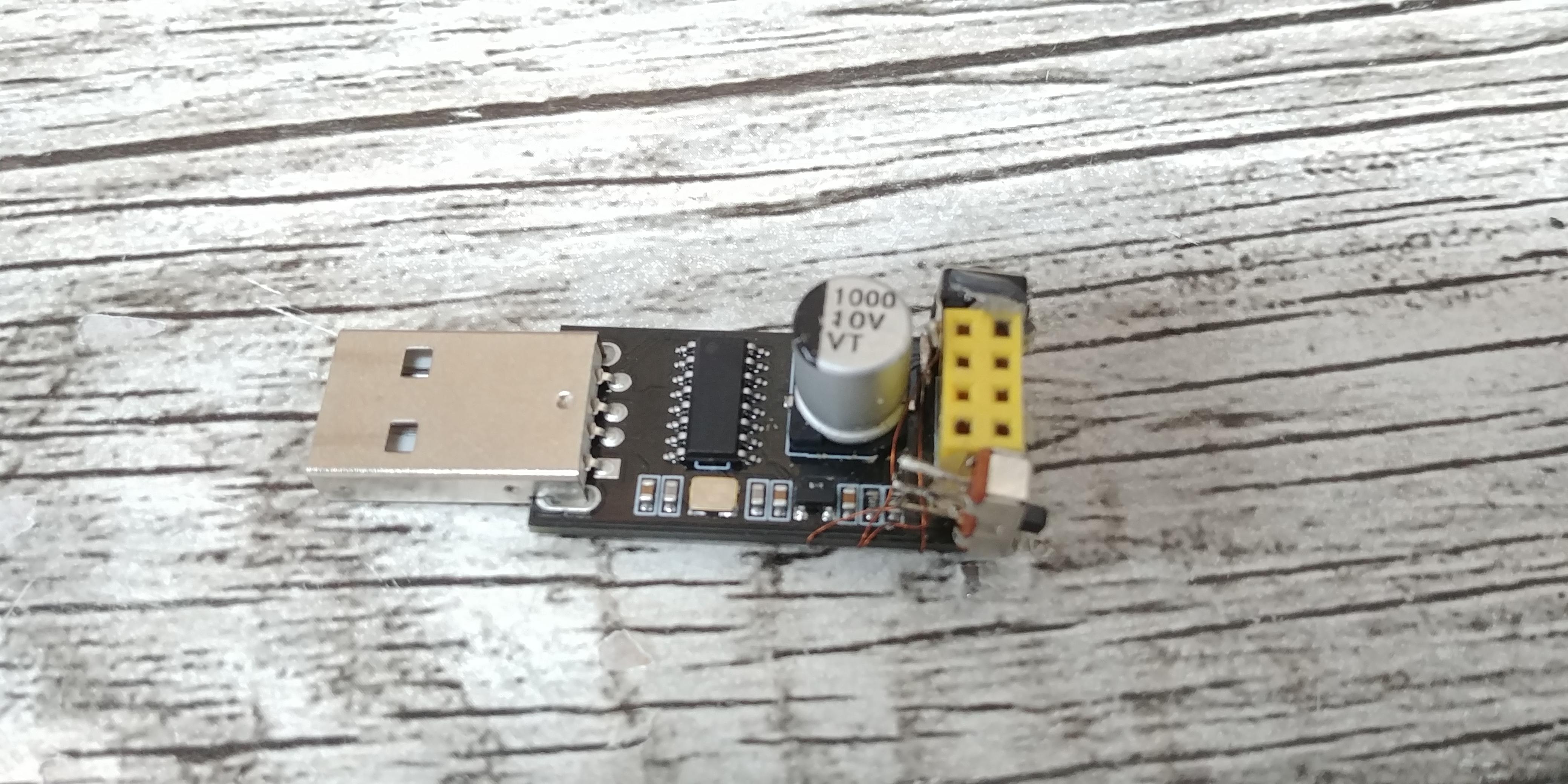
This project is fully open source, if you want to modify the code it's on my GitHub. But there is no need to. This button can be reconfigured without reprogramming.
The code can be downloaded from my latest release here.
Just plug in your ESP programmer and your ESP8266(Remember to connect GPIO_02 to GND to enter programming mode) and upload the code and the SPIFFS data.
It's very important to upload the SPIFFS data folder, without it the code will not boot. And after removing the pin headers having to go back to reprogram will be very tedious.
EDIT : If you want to use the wifi button with ESPHome , I suggest you to upload the esphome firmware instead of the normal one. You can have more info about ESPHome here : https://esphome.io/guides/getting_started_hassio.html.
Schematic
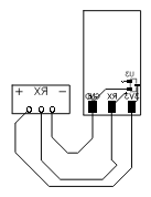
You can rely on this schematic to assemble the circuit of the button.
Desolder the Pin Header


Before proceeding with the desoldering process, please ensure that you have confirmed the correct programming of the ESP8266 module and have successfully uploaded the required SPIFFS data.
To desolder the 2x4 pin header and make the button smaller, follow these steps:
- Begin by removing the plastic housing that holds the header pins in place. Gently apply pressure on both ends of the plastic piece and carefully lift it off. This will expose the header pins for desoldering.
- Next, prepare your desoldering tools, including a soldering iron with a fine tip and desoldering braid or a desoldering pump.
- Heat up your soldering iron to the appropriate temperature and ensure the tip is clean.
- Position the tip of the soldering iron on one of the header pins, applying gentle pressure to the pin.
- With the pin heated, touch the desoldering braid or the desoldering pump to the heated pin. The braid will absorb the molten solder, or the pump will create a vacuum to remove the solder from the joint.
- Once the solder has been absorbed or removed, repeat the process for each pin of the header. Take care not to apply excessive heat for an extended period to avoid damaging the PCB.
- After desoldering all the pins, gently lift the header out of the PCB. If any pins remain in the PCB, use tweezers or pliers to remove them carefully.
- Clean the PCB pads using isopropyl alcohol and a small brush or cotton swab to remove any residual solder or flux.
By following these steps, you will be able to desolder the 2x4 pin header, allowing you to make the button smaller. However, please keep in mind that this process will prevent easy reprogramming without resoldering the header. Make sure you have already flashed the correct program and SPIFFS data before proceeding.
Solder the Main PCB

To assemble the main PCB for our WiFi button, follow these steps:
- Place the ESP01S module on top of the PCB, aligning the pads of the module with the corresponding pads on the PCB.
- Ensure that the ESP01S module is properly aligned with the PCB to ensure accurate soldering and a secure connection.
- Once the module is in position, use a soldering iron to solder each pin of the ESP01S to its corresponding pad on the PCB.
- Apply a small amount of solder to each pin while ensuring that the solder flows smoothly and forms a solid connection between the ESP01S and the PCB.
- Pay close attention to solder each pin correctly, avoiding any short circuits or cold joints. Take your time and double-check each solder joint to ensure accuracy.
- After soldering all the pins, visually inspect the solder joints to ensure they are clean, free from bridges, and securely connected.
- Allow the soldered PCB to cool down before proceeding to the next steps of the assembly process.
By carefully following these steps, you will effectively solder the ESP01S module to the first PCB, creating the main PCB for your WiFi button.
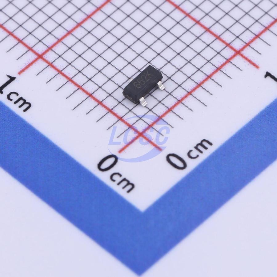
Solder the Linear Voltage Regulator


Next, we proceed with soldering the Linear Voltage Regulator onto the PCB.
Solder the Pushbutton

To connect the pushbutton to the ESP01S module, you will need to solder it between the Ground (GND) and Reset (RST) pins of the Esp01s
Connect CH_PD to VCC
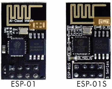
If you have an Esp01, you need to connect CH_PD to VCC. If you have an Esp01s like in my case , you dont need to connect them so you can skip and go to the step. You can refer to the image to know wheter you have an Esp01 or an Esp01s.
Remove the Power LED
Again, if you have an esp01s you can skip this step. The button needs to consume as little power as possible. And since it is always on, the power led would always be consuming ~4mA. This would reduce the battery life to twelve hours. So desolder it or snap it off.
Solder the Battery


To solder the battery, follow these steps:
- Locate the 3.3v pin on the back of the PCB.
- Connect the positive wire from the battery to the 3.3v pin.
- Find the GND (ground) connection on the PCB.
- Connect the negative wire from the battery to the GND pin.
Make sure to solder the wires securely to the pins, ensuring good electrical contact.
Solder the 2 PCB Together


To connect the two PCBs, follow these steps:
- Locate the 3.3V pin on the main PCB and identify the + pin on the second PCB.
- Use a soldering iron to join (solder) the 3.3V pin of the main PCB with the + pin on the second PCB.
- Similarly, find the RX pin on the main PCB and locate the RX pin on the second PCB.
- Solder the RX pin of the main PCB with the RX pin on the second PCB.
- Finally, identify the ground pin on the main PCB and locate the - pin on the second PCB.
- Solder the ground pin of the main PCB with the - pin on the second PCB.
You can also refer to the circuit diagram / schematic
Put the Circuit in the Case


- Start by sliding the ESP01s into its designated hole. Make sure it fits properly and aligns correctly.
- Next, insert the LiPo battery after placing the ESP01s in its position. Ensure that the battery is correctly connected to the ESP01s.
- Once the ESP01s and battery are in place, you can test whether the button works. Press the button and check if it functions as intended.
- If the button works correctly, proceed to the next step. In this step, you need to attach the PCB (printed circuit board) to the 3D printed case, as shown in the provided images. To do this, use glue or an appropriate adhesive to secure the PCB inside the case.
The Charging Base
We will now make the base that will charge our button.
The Schematics

You can rely on this schematic to assemble the circuit of the base.
Solder the 3 Connectors on the PCB


We need to connect the small connector using soldering. I recommend using tweezers because it can be challenging to position the connectors accurately without them
Solder the Pushbutton on the PCB


Next, we need to connect the pushbutton to the PCB by soldering it.
Solder the Base's PCBs

To properly solder the PCBs and the charging module, you can refer to the diagram.
Put the Circuit in the 3D Printed Case

Now you can place the PCB with the three connectors in its designated slot at the top, and the PCB with a pushbutton in its designated slot at the bottom. Additionally, you can attach the charging module to the bottom plate, aligning it with the hole for the USB port, and secure it in place using glue.
After confirming that everything is functioning properly, you can proceed to attach the bottom plate to the base using glue.
Configure

To prepare your button for its initial use, follow these steps:
- Place the Wi-Fi button in the base.
- Simultaneously press the button on the Wi-Fi button and the button on the back of the base. This will put the button in configuration mode.
Next, you can proceed with the following instructions:
- Connect your device to the 'ESP_Button' Wi-Fi Access Point. Use the password 'wifibutton' to connect successfully.
- Open a web browser and visit the URL http://192.168.4.1. This will take you to the configuration page.
- On the configuration page, enter the necessary values according to your requirements.
- Once you have entered your desired values, click on the 'Save' button.
- After saving the configuration, click on the 'Restart' button to reboot the button.
- The button will restart, perform the requested action, and then enter deep sleep mode.
When configuring the host field, only type the hostname without including 'http://' or 'https://'. For the URI fields, separate the rest of the URL as required.
Following these steps will ensure that your button is ready to be used successfully.
Enjoy


Congratulations! Your button is now ready for use in any way you desire. Feel free to explore the possibilities and utilize it for your specific needs.
If you encounter any issues or require assistance with troubleshooting, please don't hesitate to leave a comment below. I'll be happy to help you out.
Furthermore, I welcome any ideas or suggestions for improving this project. If you have any feedback or recommendations, please share them in the comments.
Let me know if you would like me make more projects like this in the future.