Doll House Lighting

This Instructable details how to supply electrics and lighting to a Doll House. Based around my 1960s Doll House design but can be used in any other Doll house. See my 1960's Doll House build Instructable here .
I have split the huge 1960's Doll House build into multiple parts with this part detailing the wiring of lighting and switches for each room. I have designed 3D printed switch boxes to hold banks of switches which can be added to as and when extra electrical devices are added to your Doll House.
I will add a seperate Instructable detailing various electronic add ons I have built into my Doll House.
Pic 1. Lights testing.
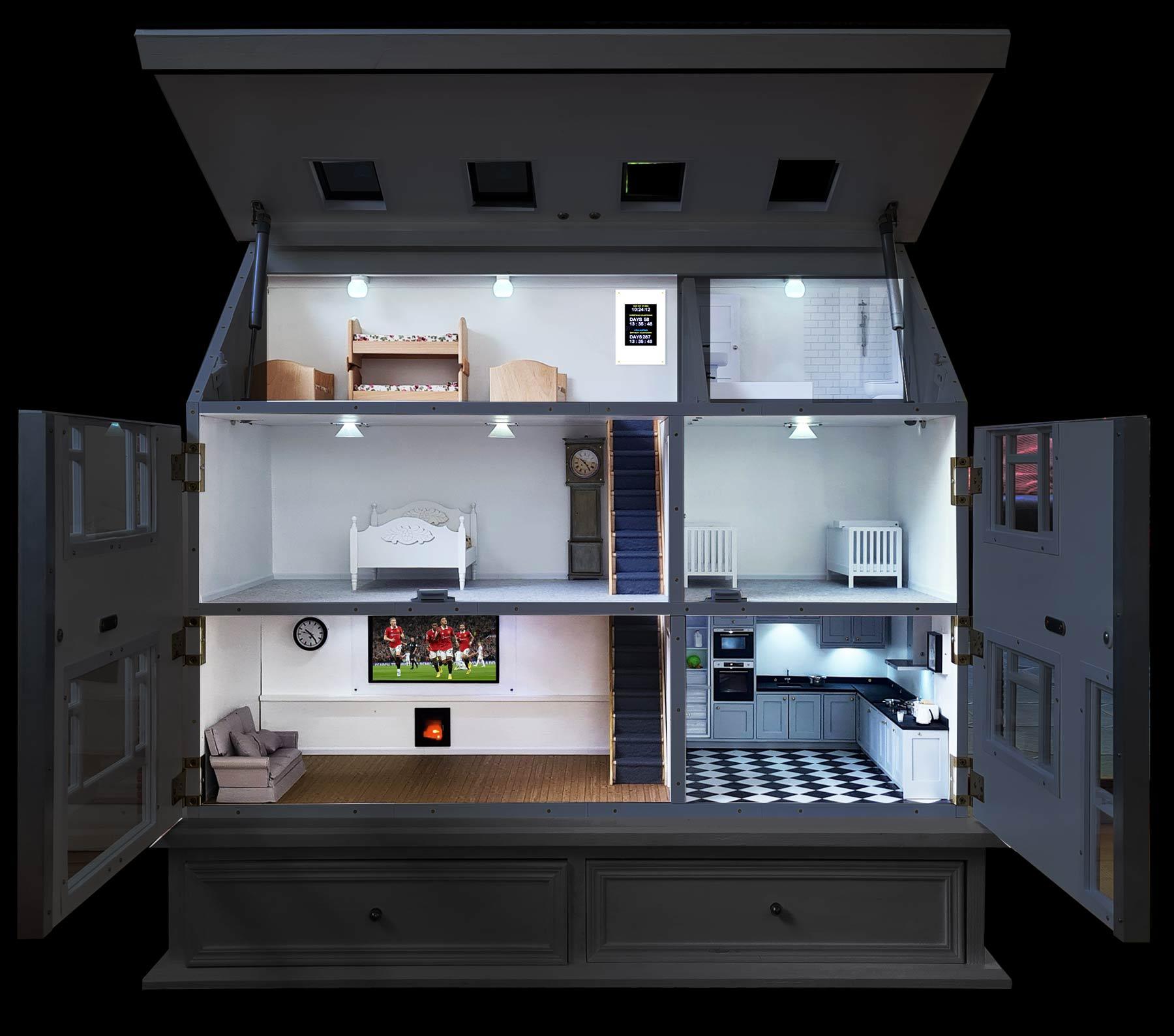
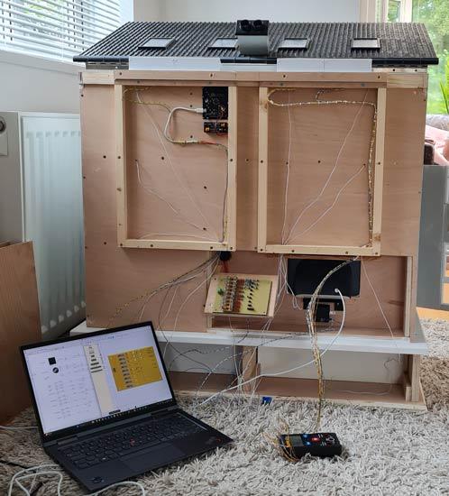
Pic 2. Doll House with all lights turned on.
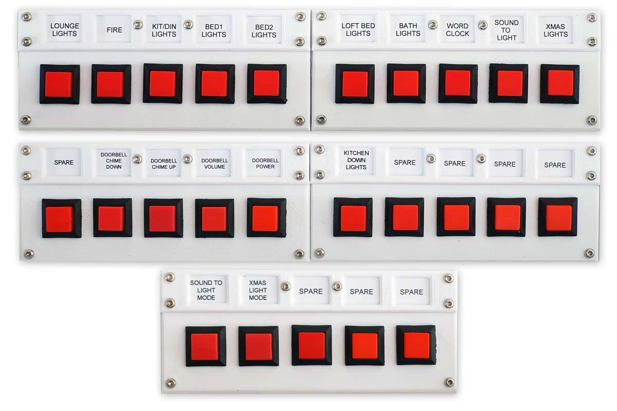
Pic 3. Switch modules.
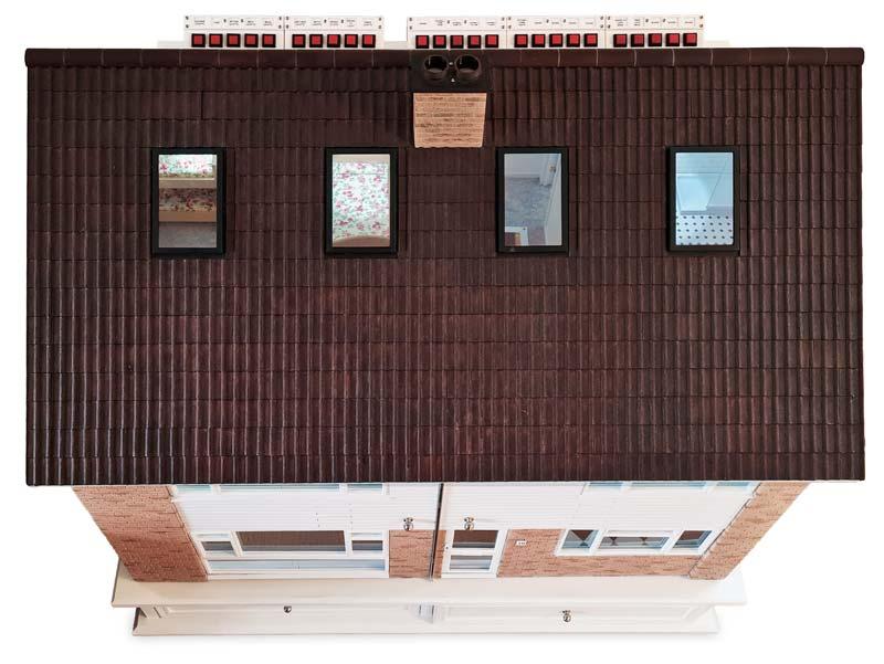
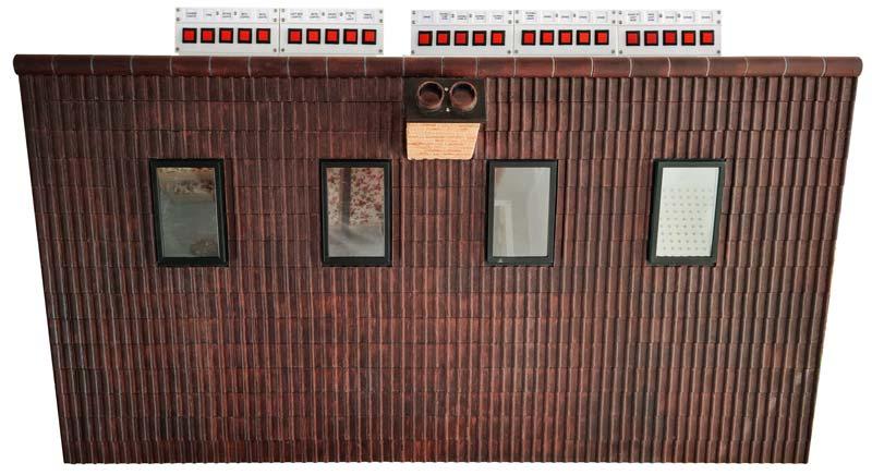
Pic 4. Switch Modules in place hidden behind the roof line.
Supplies


Pic 2. 12mm Mounting Hole Red Square Latching Push Switch https://amzn.eu/d/hYh0g3B Qty as required
Pic 3. 12mm Mounting Hole Red Square Non Latching Push Switch https://amzn.eu/d/aX0Imk1 Qty as required
White PLA/PLA+ 3D filament
0.5mm solid wire https://amzn.eu/d/dJD1I3k Qty as required
Vero Board as required depending on quantity of fuses, LEDs and or circuits used.
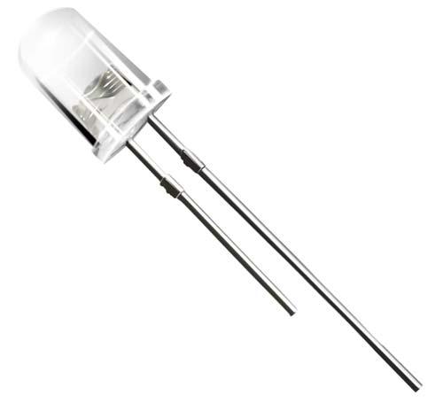
Pic 1. LEDs (long leg to +ve) https://amzn.eu/d/4nKblZ2 Qty as required depending on number of rooms.
Resistors 180 Ohm https://amzn.eu/d/9vjeILD Qty 1 per LED
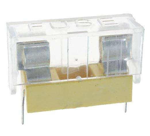
Pic 4. Fuse Holder https://amzn.eu/d/g2Aw1Gb Qty 1 per LED circuit or accesory.
Pic 5. Fuse 20mm 0.2A https://amzn.eu/d/iNrNXqb Qty 1 per LED circuit or accesory.
M2 hex bolts 8 off per switch box
M2 self tapper/wood screw 2 off per switch box.
Power supply. A 2A 5v power supply should be fine for lighting and many other additions to the Doll House. I use a standard Android phone charger.
Switch Box
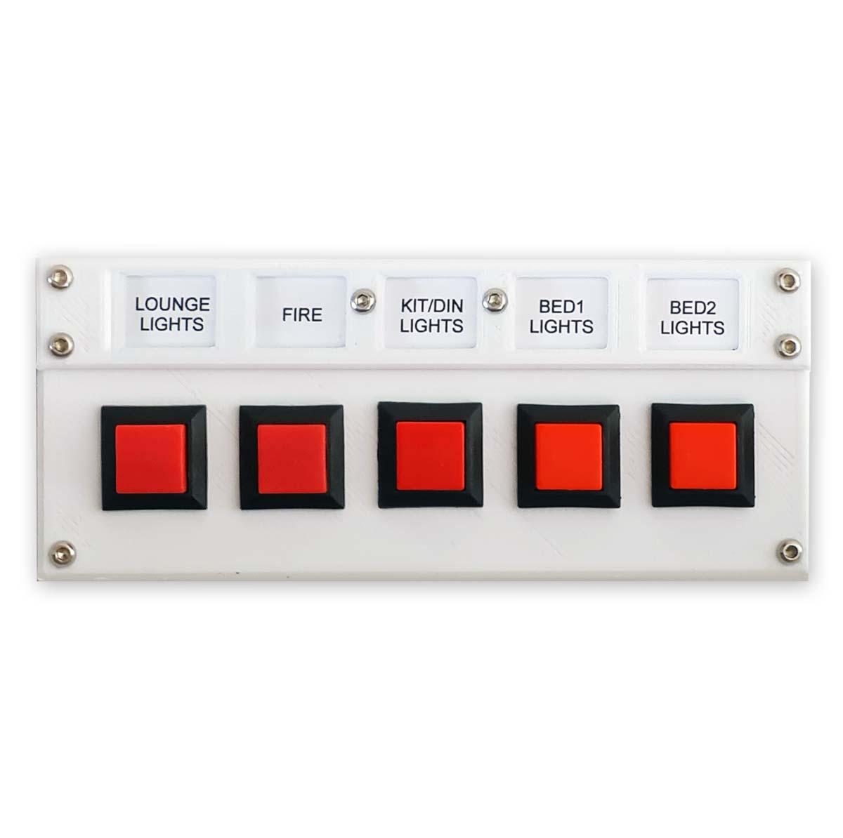

Pic 1. Each switch box can house five switches. These switches can be latching or non latching type depending on their use.
Pic 2. Shows the 3D printed parts in order of asembly.
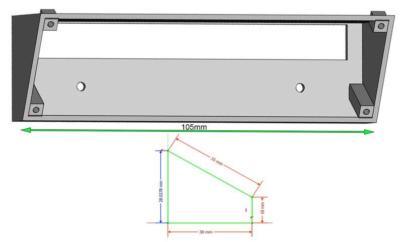
Pic 3. This pic shows the dimensions of an indiviual switch box.
Pic 4. Full set of switches in position behind the roof.
If you need more switches just add another switch box up to a maximum of five (25 switches in total).
The switch boxes are 3D printed and are screwed together using M2 hex bolts direct into the plastc.
Lights

LEDs are fitted into 3D printed light shades, two in the lounge, master bedroom and loft bedroom and one each in bedroom two, kitchen and the bathroom.
There are two type of light shades both printed from clear 3D filament.
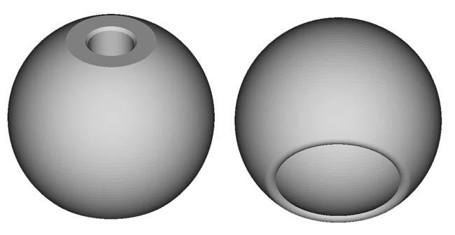
Pic 1. 6 off required Lounge x 2, bed 1 x 2, bed 2 x 1 and kitchen x 1 https://www.printables.com/model/309186-dollhouse-lampshades
Pic 2. 3 off required Loft Bed x 2, bathroom x 1 https://www.printables.com/model/309186-dollhouse-lampshades
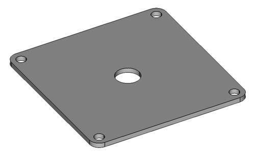
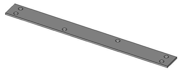
Pic 3 is a 3D printed light bracket for the shade in pic 1. The shade is super glued to the bracket which is screwed to the ceiling hole with M2 wood screws. An LED is fitted through the hole in the back.
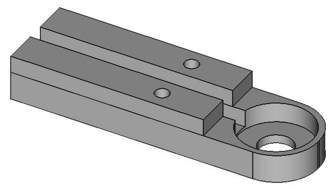
Pic 4 is the bracket for the shade in pic2 and the shade is super glued in place.. These shades and bracket go in the loft rooms with the wires fed down the central channel.
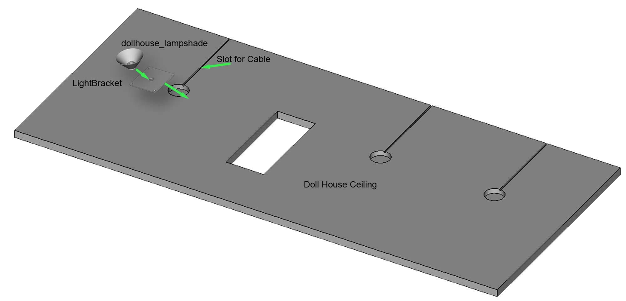
Pic 5 In order to fit the wires into the lights on the ground and first floors slots are cut from the back of the ceiling to 30mm holes into which the LED and a bit of slack wire is fitted.
First drill a round recess with a 30mm Forstner Drill Bit . This recess is to allow space for the LED connection and wire to sit. Then cut a narrow slot for the wires from the rear of the board to the hole. To cut the slots I used a Oscillating Multi Tool saw. A tenon saw would work if not cut the slot using a craft knife.
The brackets in pic 3 are fitted over the hole with optional "wiringcover" pic 6 screwed over the top.
Wiring

Pic 1. Full size schematic can be viewed here.
Note the schematic and Vero board layouts show my Doll House with all add on gadgets installed. I will do a further Instructable including all the gadgets.
Just install the parts of the schematic as required.
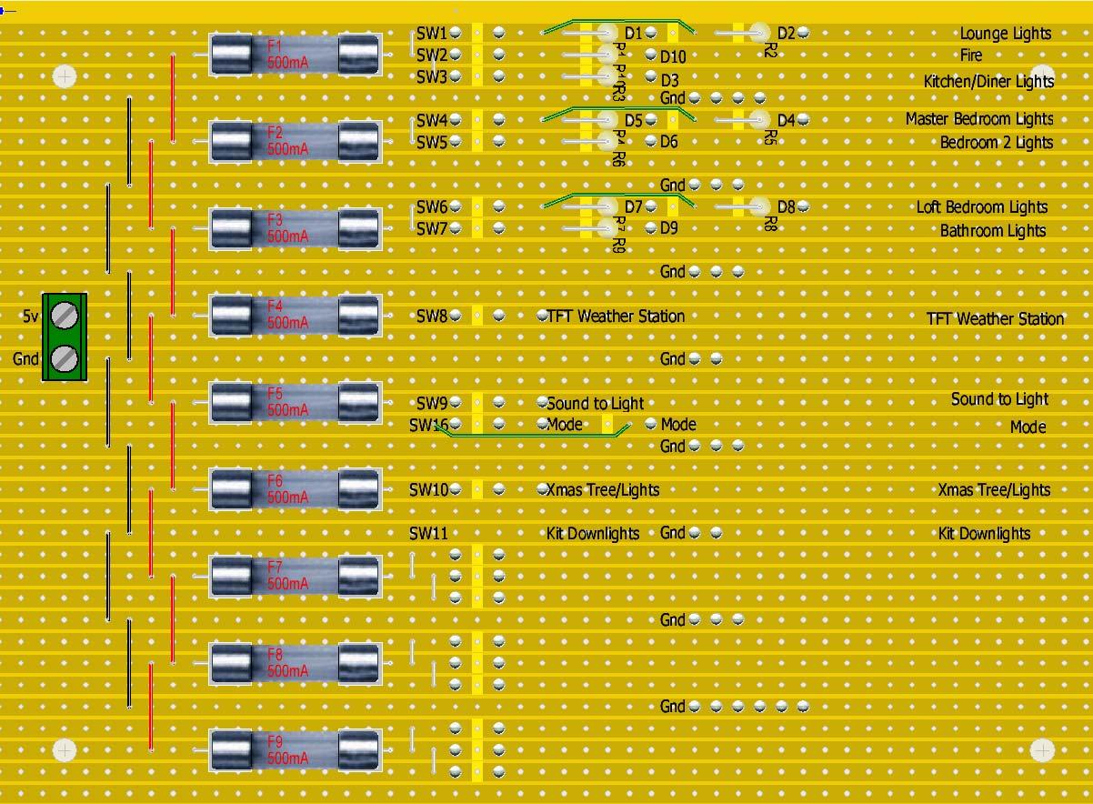
Each fuse covers a number of circuits with each circuit controlled by a switch.
Pic 2. Wiring is taken out the rear of the doll house and through a series of boxes (timber batens with 6mm plywood tops) that cover the wiring and any circuit boards including the Vero board and fuses.
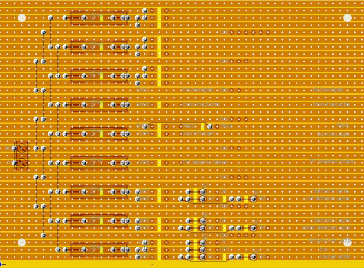
Pic 3 & 4 show the Vero board layout front and back.
Main 5v power. Cut the end off the power supply cable and terminated it on the screw terminal on the Vero board.
The wiring from the switches is taken down through the bottom of the switch boxes and through the wiring boxes.
Final Testing

Put fuses into the holders and then turn on the power supply. Check each light turns On & Off with the correct switch.