Don't Bake Cookies in Your Car (Car ≠ Oven)
by wannabemadsci in Workshop > Solar
216 Views, 0 Favorites, 0 Comments
Don't Bake Cookies in Your Car (Car ≠ Oven)
Your car should not be an oven, unless you are planning on baking cookies in it!
And typically, it doesn't get quite hot enough to cook effectively .... But how hot does it get?
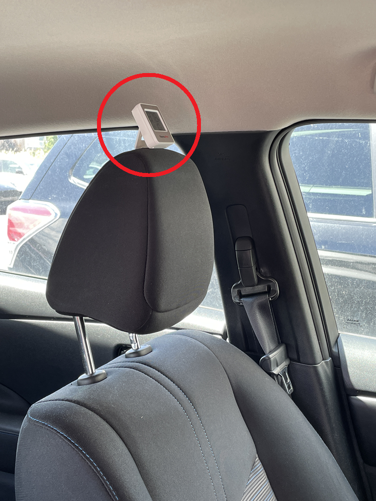
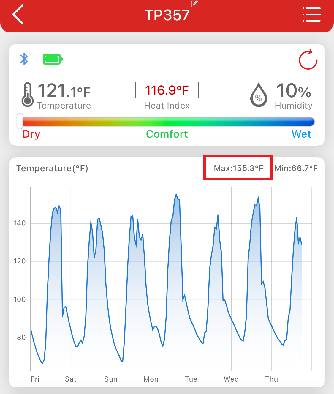
I answered that question by putting a logging thermometer on top of the headrest in my car. I took temperatures at home and at work for a week and was surprised to see temperatures topping out at 155 Degrees Fahrenheit (68°C).
155 °F!
That is a lot hotter than I expected.
I did have a windshield shade in place, but in the interest of transparency I have to admit that we did have triple digit temperatures the same week.
Because the car is so roasting HOT, I thought it would be a good idea to provide some type of ventilation to prevent the heat from building up in the car cabin.
I thought I'd make a solar-powered car ventilation system!
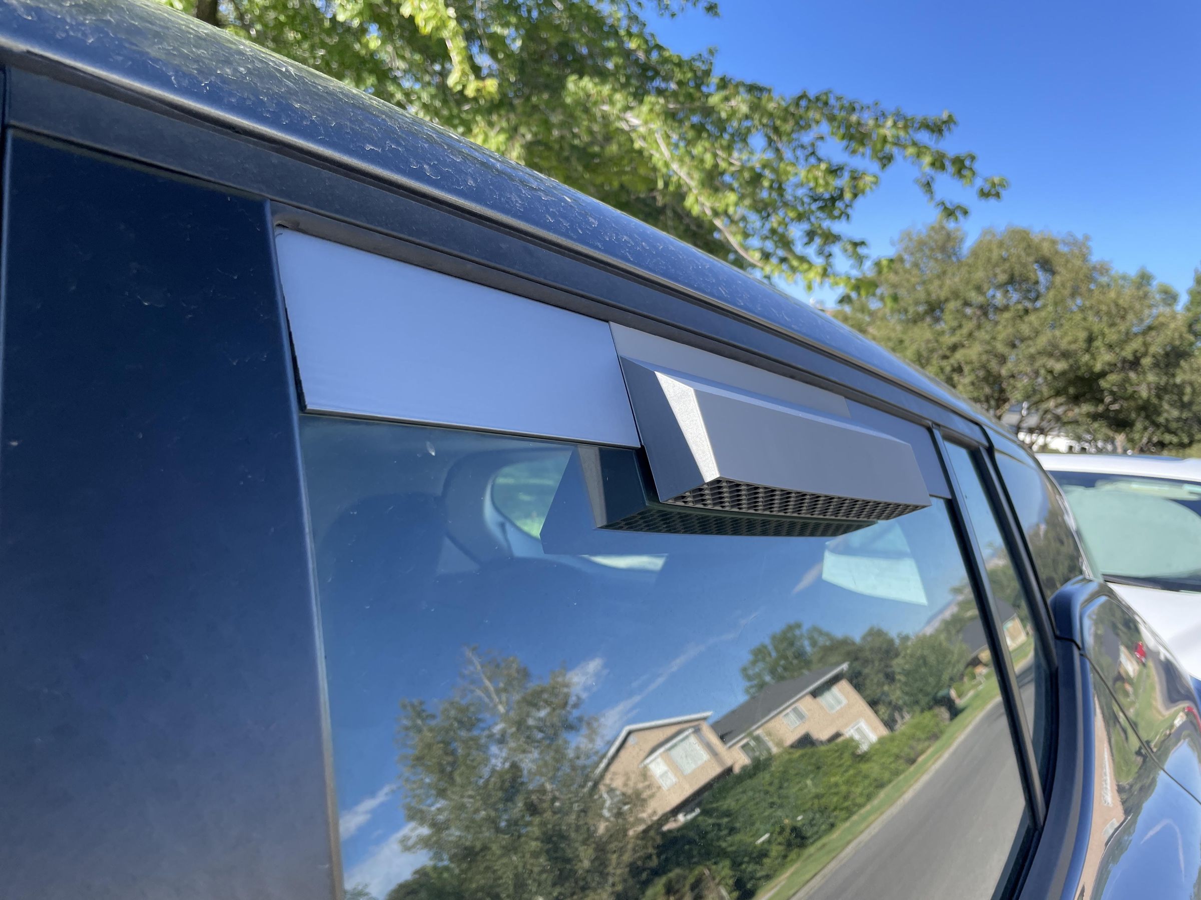
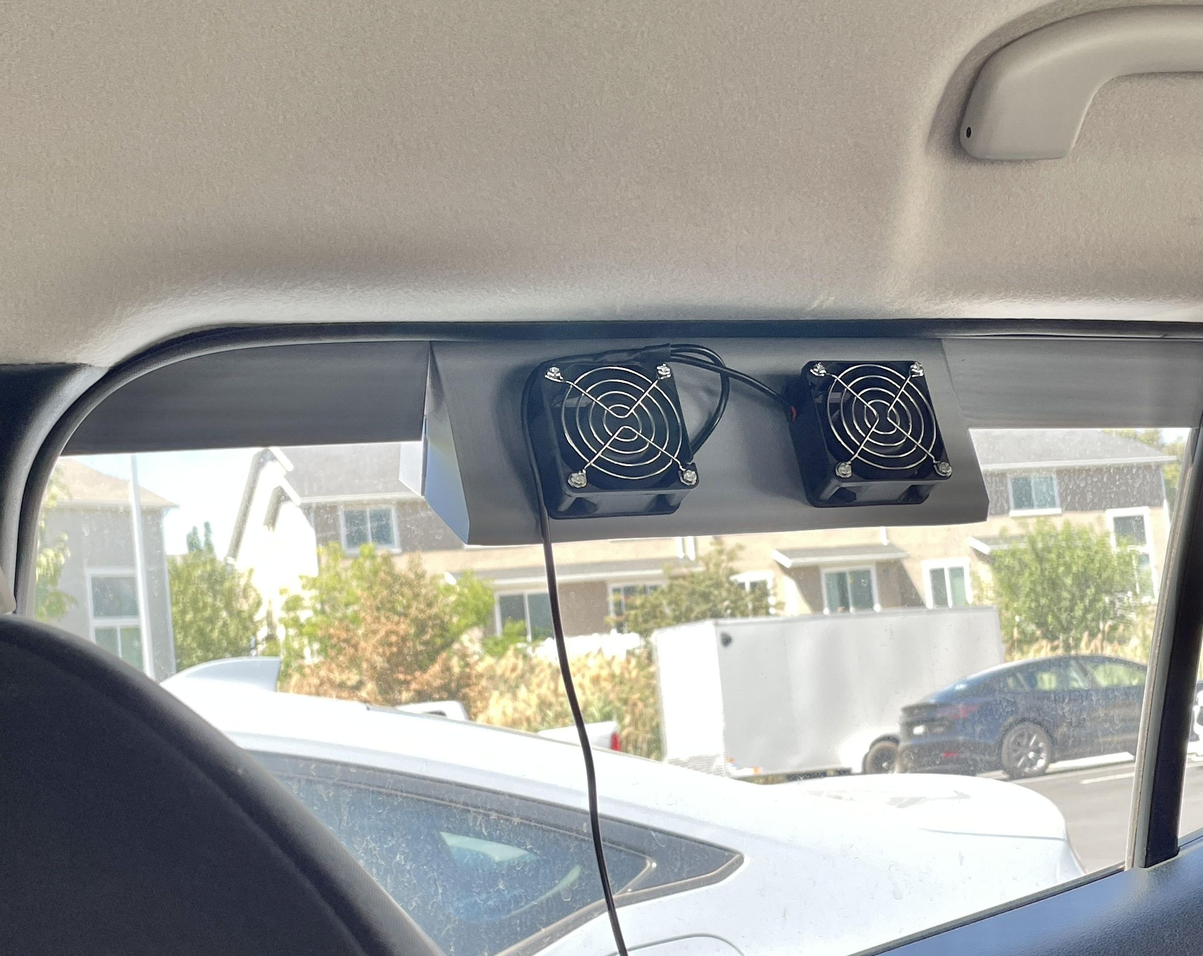
The system consists of two basic parts. The exhaust portion with fans, and the fresh air inlet. Both mounted in slightly open windows on opposite sides of the car. I powered it all with a solar panel set on the dashboard.
Let the building begin!
Supplies
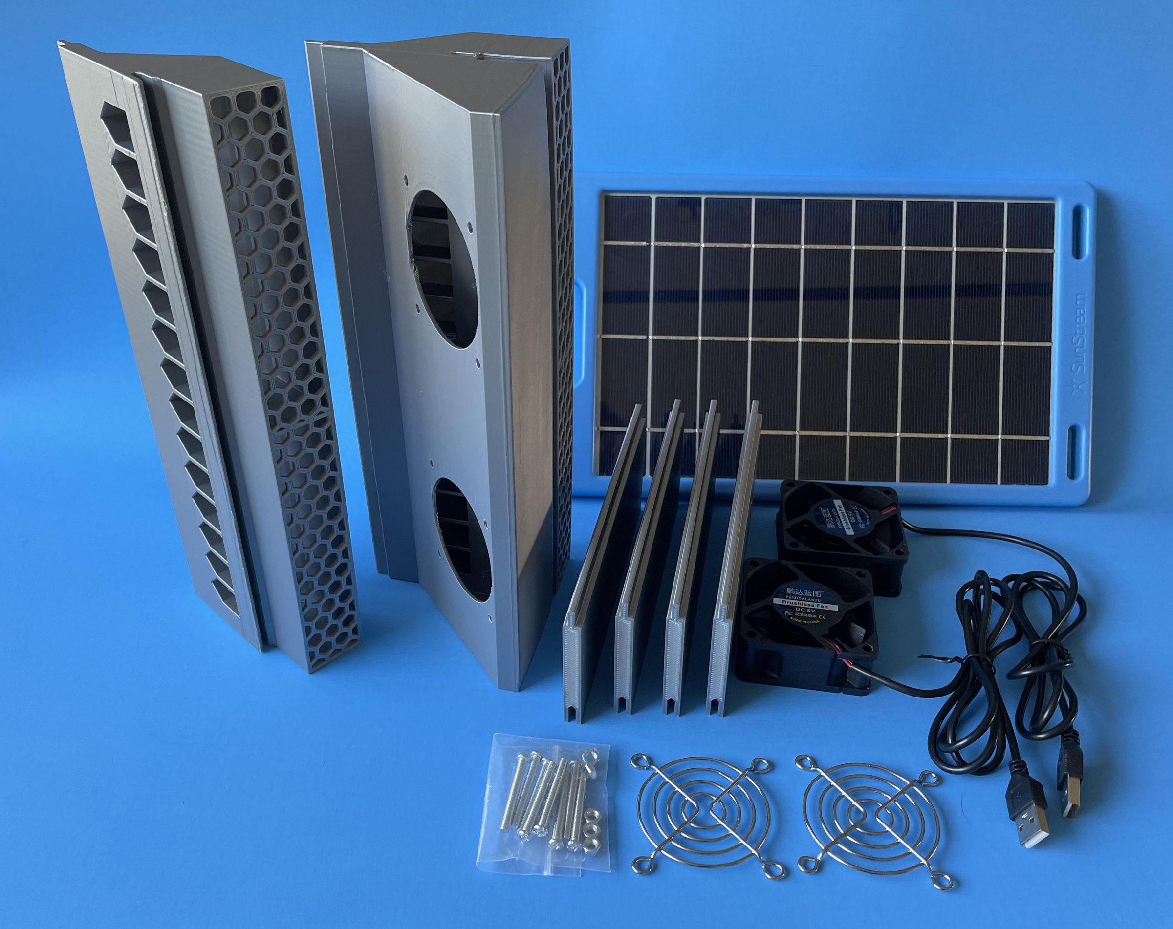
- 1 - 3D Printed Window Air Inlet Assembly
- 1 - 3D Printed Window Fan Exhaust Assembly
- 4 - 3D Printed Window Side Filler Plates
- 2 - 5Vdc USB Computer Fans, 60mm x 60mm x 25mm, 20.4 CFM, ball bearing with wire grills and mounting hardware
- 1 - 5.5Vdc, 1.2 Amp (6W) Solar Panel - I had this on hand and wanted to have plenty of power available.
Not shown: Solder, heat shrink tubing, USB A Extension cable
Assess Your Car Windows
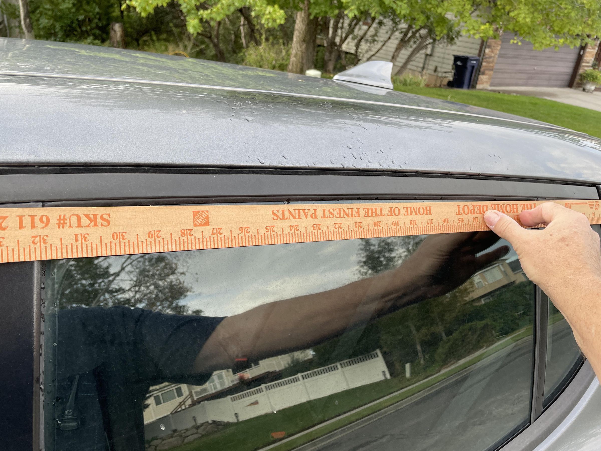
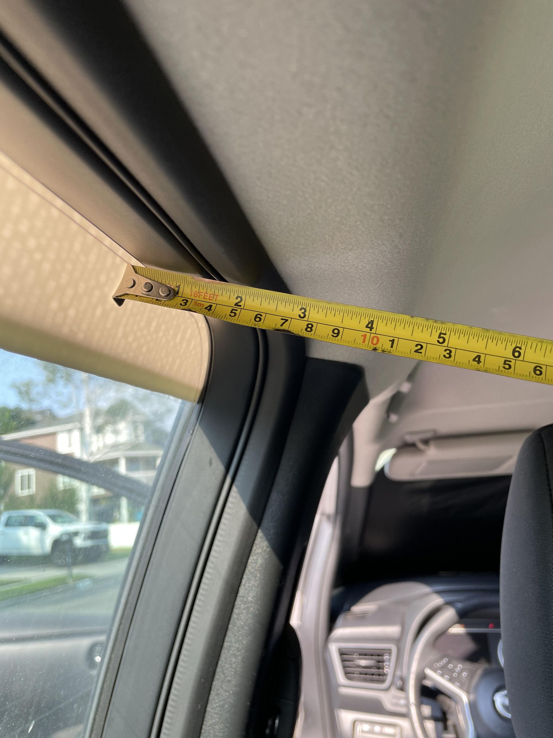
I decided to mount my exhaust fan assembly and air inlet assemblies in the car's rear passenger windows. I thought opening the windows slightly would provide an area where I could use the glass and door frame gasket to capture my ventilation units. I thought it wise to only allow about 2 inches (50.8mm) of opening in case someone tried to remove the ventilation units and get their arm inside the car. I don't know if that was good logic, but the opening I considered using I limited to 2 vertical inches.
I had to measure the width of the window opening and also take into consideration the door frame and interior ceiling liner and trim. The interior portions of the car encroach on the free space next to the window and you have to take it into consideration when extending the ventilation units into the interior of the car.
I noted that the top edge of the glass and the door frame were curved and originally thought it was critical to take this into consideration when designing the ventilation units. However, after installing them in the window openings I think it is less critical and might have been able to have been ignored.
You have to take into account the thickness of the window glass, so it is important to measure that as well.
Design the 3D Printed Fan Exhaust Assembly
.png)
.png)
.png)
.png)
.png)
.png)
The whole Exhaust Fan Assembly is based around the Filler Plate that fills the gap of the open window. The first image shows the sketch of the cross section of the plate. It has a slot in the bottom that fits over the window glass and a tab on the top that becomes the 'new window glass' to fit into the top window gasket.
I had mentioned that the top edge of the window glass was curved. Taking those dimensions, the second image shows how I created a sketch of the curvature of the glass and then used the SWEEP function in Fusion 360 along with the cross section of the filler plate to create the filler plate solid model.
The interior and exterior portions of the Exhaust Fan Assembly are essentially air plenums, 'ducts' for air, along inside and outside of the window fill plate that form the passageway for the air to flow through. They are basically triangular cross section designs. Triangular with 45°angles so that no supports are needed when 3D printing them. In the third image, the left side is inside the car glass (the fans are mounted to this side) and the right side is outside the car glass.
There needs to be some type of pass through between the inside plenum and the outside plenum. This was accomplished by adding 'little house'-shaped openings in the filler plate solid as shown in the fourth image. The 'roof' of the opening is again at a 45° angle, so no supports are needed when 3D printing.
I wanted to have some type of screen on the exhaust air opening and I decided on a honeycomb pattern. From the internet I learned that a square screen pattern and a honeycomb pattern both allow the same amount of air to escape and that the honeycomb pattern is stronger, so I decided on honeycomb. There is also anecdotal evidence that the honeycomb pattern may repel wasps, so why not?
My opening dimension is 4mm but was a little large as I wanted to essentially keep wasps, large insects out. I probably should have made the dimension smaller and/or the thickness of the pattern narrower. But it was a compromise and it is what it is. I found this YouTube tutorial very helpful in designing the honeycomb pattern in Fusion 360: https://youtu.be/u4Fb3Jfl98w?si=jEzEp4qu4SvaAtFc
I added internal vertical walls in the plenums to separate the two fans, both on the fan side and on the outlet side so that if one fan failed it would not be possible for the operating fan to blow hot air back into the car interior.
Note: The 3D previews do not show the print orientation. The vents were printed with the honeycomb on the build plate, and the Fill panels were printed with the small end on the plate, printed up vertically.
Print Multiple Test Fit Cross Sections
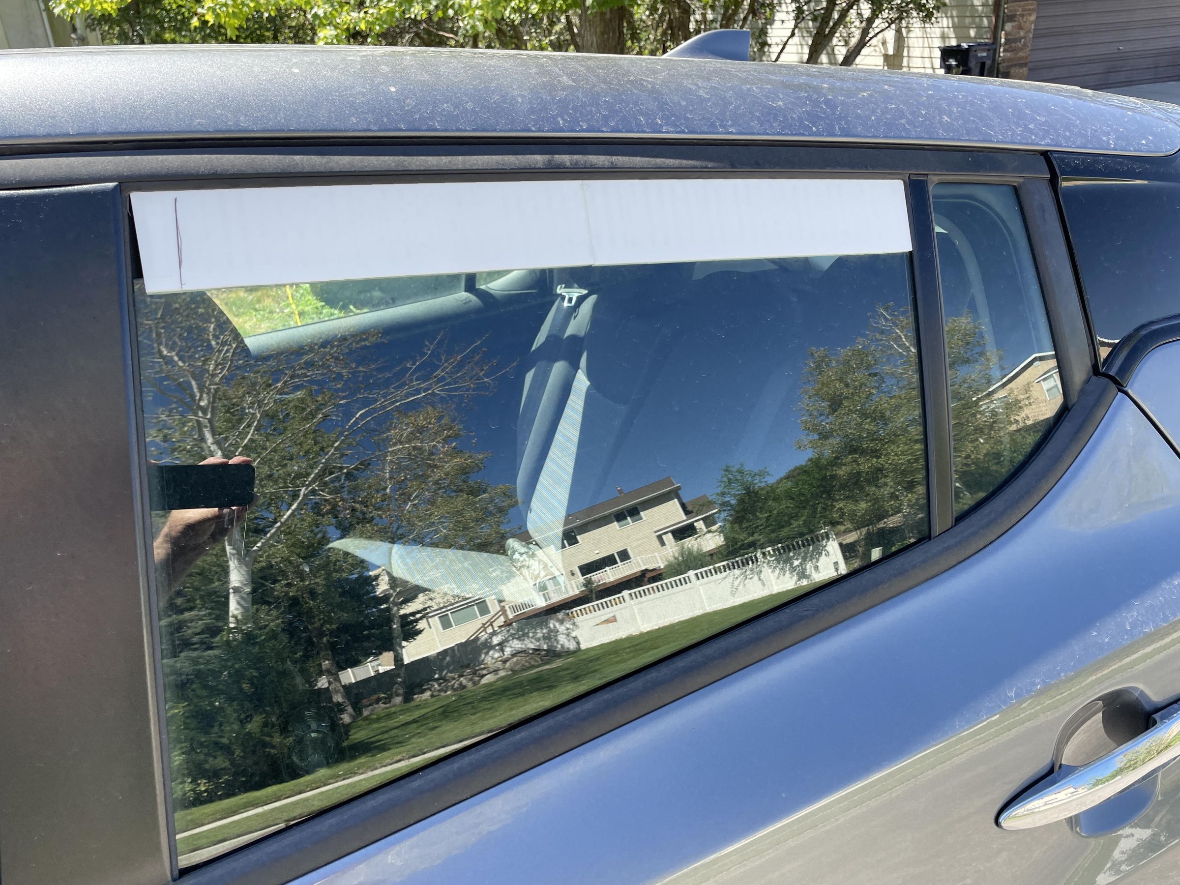
Since all these 3D printed parts have to fit into fixed existing openings, getting their dimensions correct is critical. The Fill Plate is the basis for all the other parts, so I printed just the fill plate, and test fitted it in the window opening, shown in the first photo. It worked well and then I was able to continue to design the remainder of the parts around it.
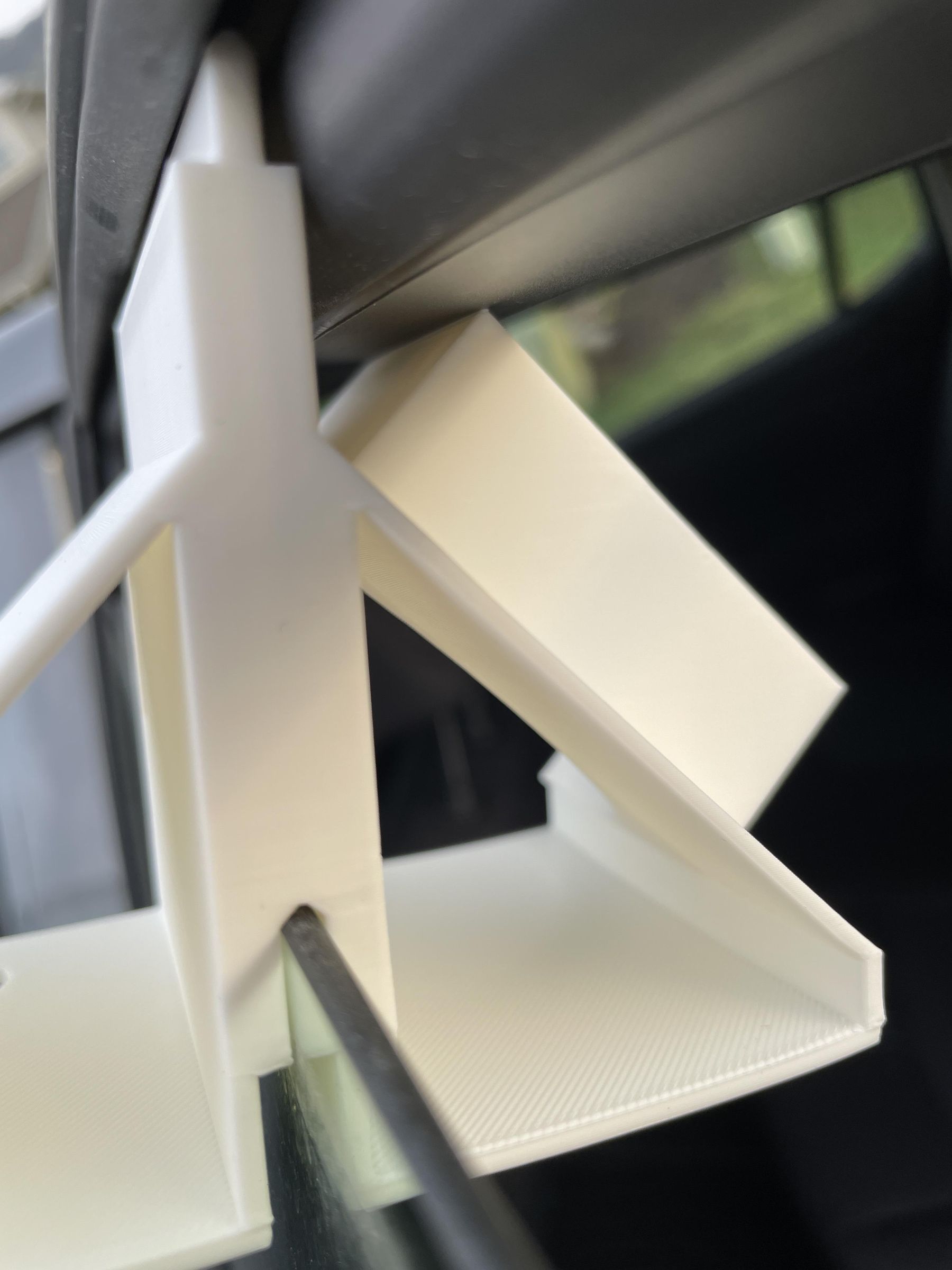
Printing cross sections of the parts was essential to ensuring that the part would fit in the window and that the fans, for example, would not hit the interior of the car. I added a solid placeholder for the fan bodies, and it pointed out that my design would have the fan hit the door frame as shown in the second photo. Note the top tab is not fully into the door gasket when the fan hit the frame - bad design. The third photo shows the final design.
All these tests were important to getting the fit correct without printing a complete assembly each time.
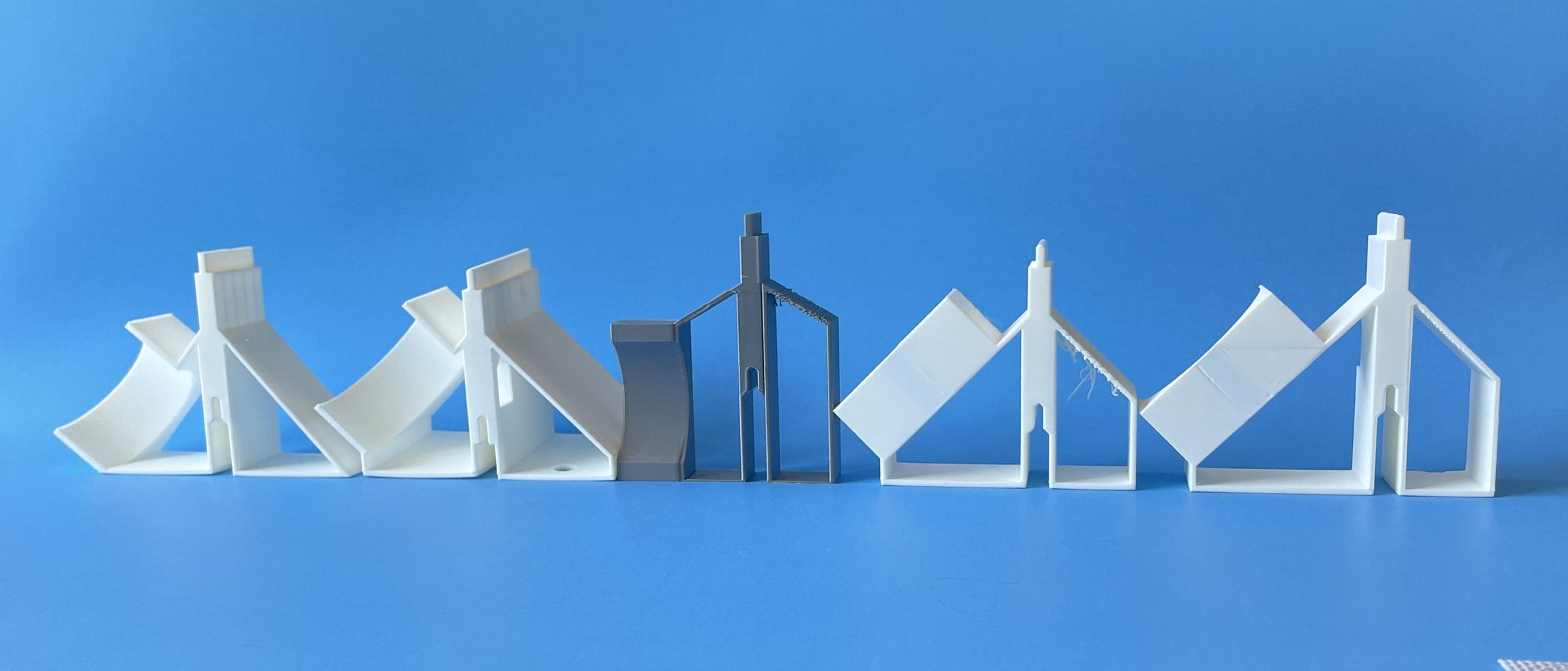
The last photo shows some of the different designs I tried. Here are some comments, from left to right:
A. Just mirrored triangles with 45° top surfaces for easy printing. Didn't have room for mounting holes for the bottom of fan.
B. Elevated the fan so it had the needed mounting holes, but fan was too high and hit the door frame.
C. (Gray) Tried fan mounted vertically with 60° top surface, which didn't print well. Pulled in outside profile so it did not stick out so far.
D. Fan body still too high on assembly and would hit door frame. Some concern about cross section area for air to flow in.
E. Final Design! Dropped fan in relation to top tab by increasing size of interior triangle. Air passage cross section increased. Kept outside protruding vent close to the car.
Print All the Assemblies
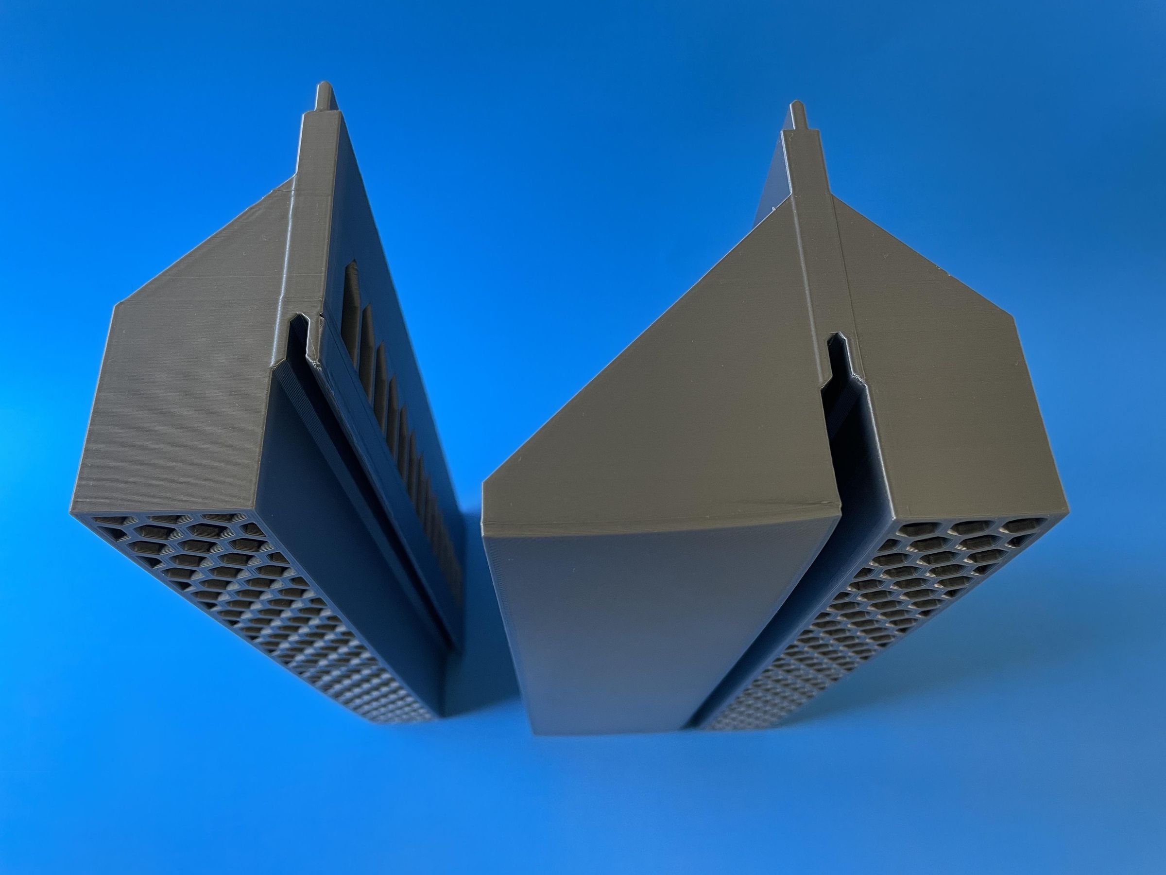
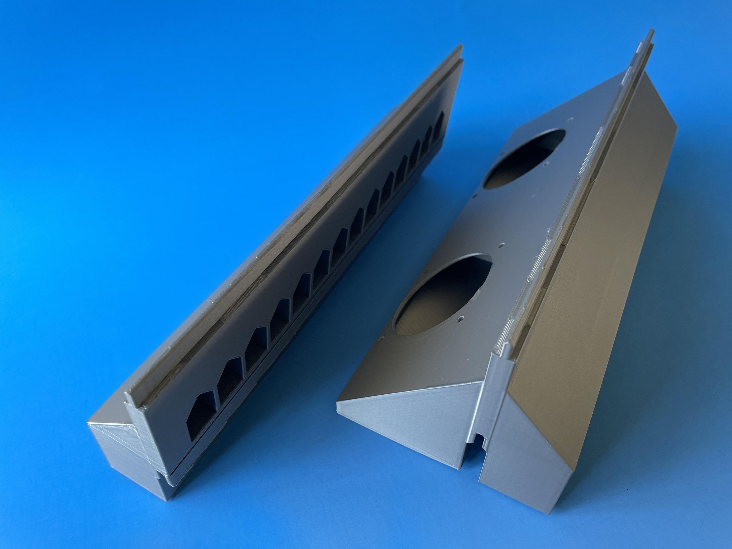
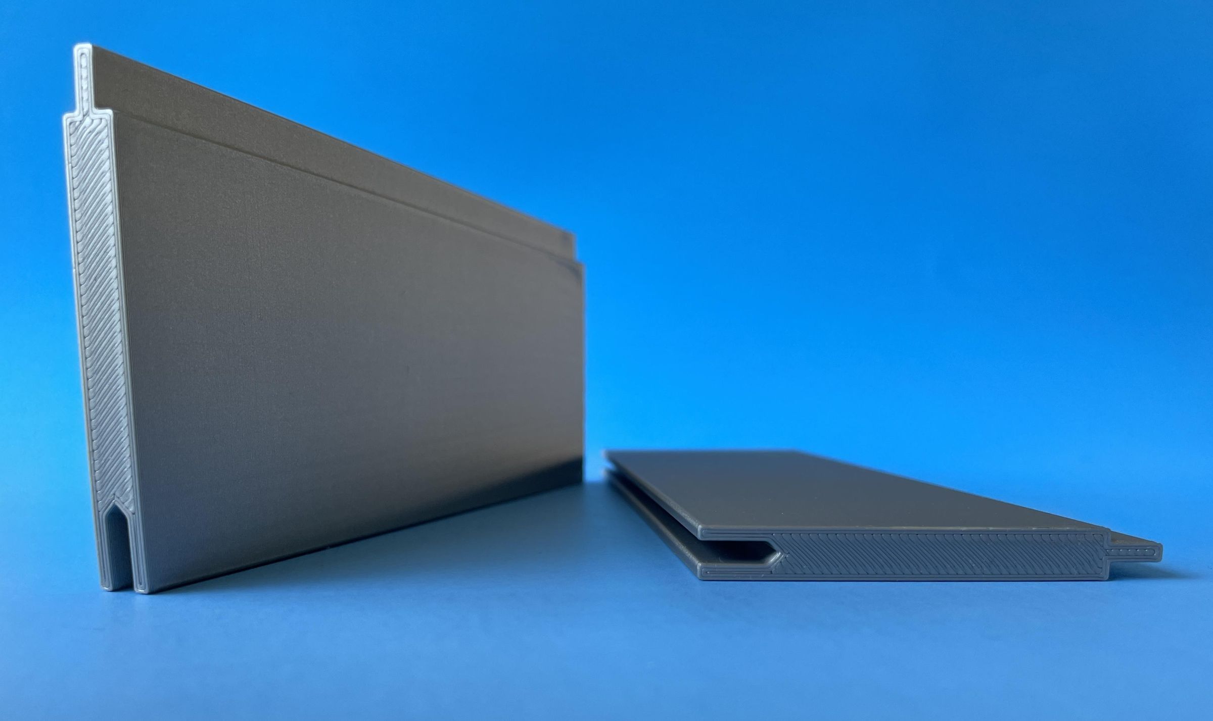
The designs were made so that no supports were needed when printing. I printed these in PLA but the temperatures are too high for PLA and I will ultimately reprint them in ASA for the higher temperature and UV resistance.
Mount Fans
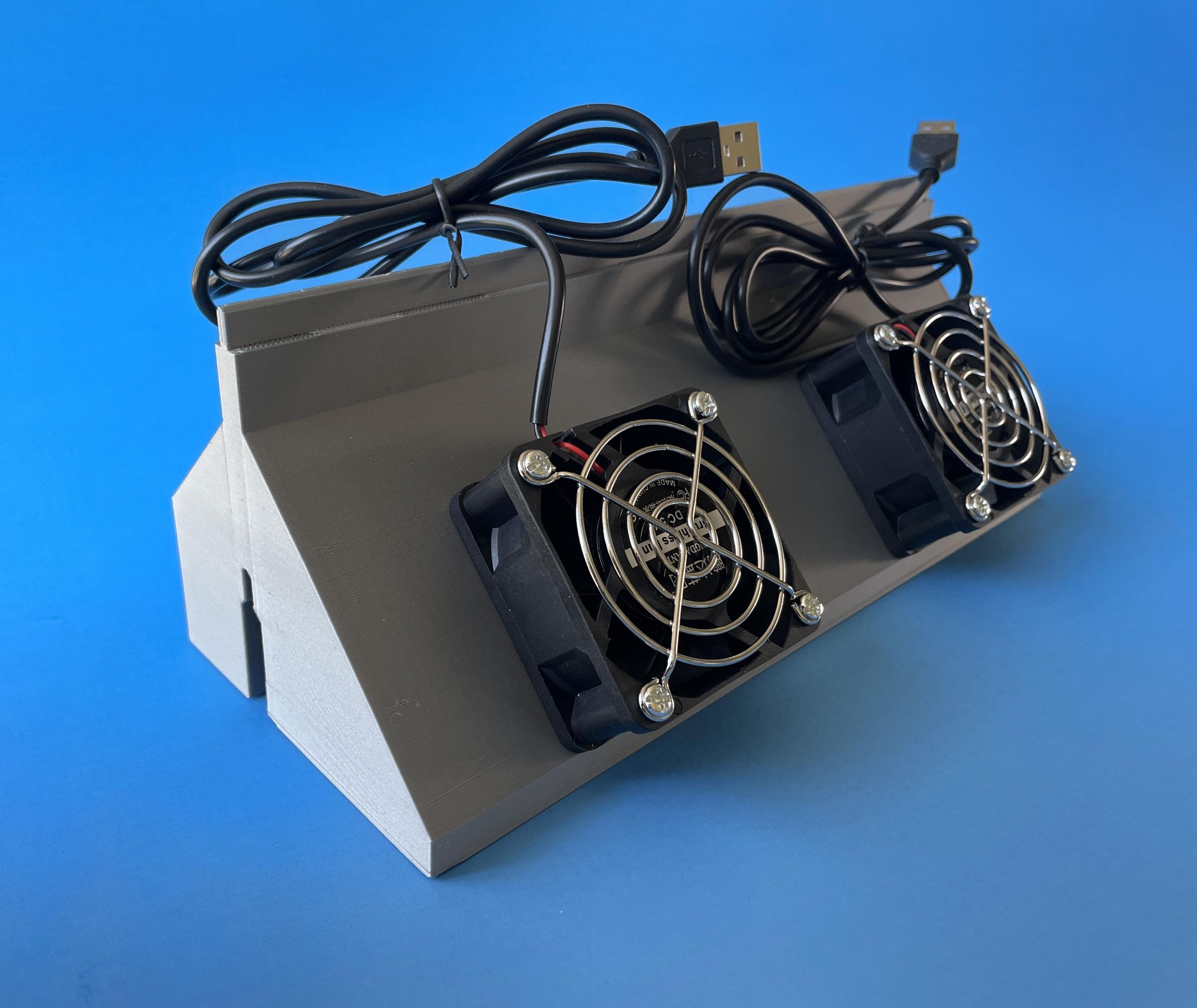
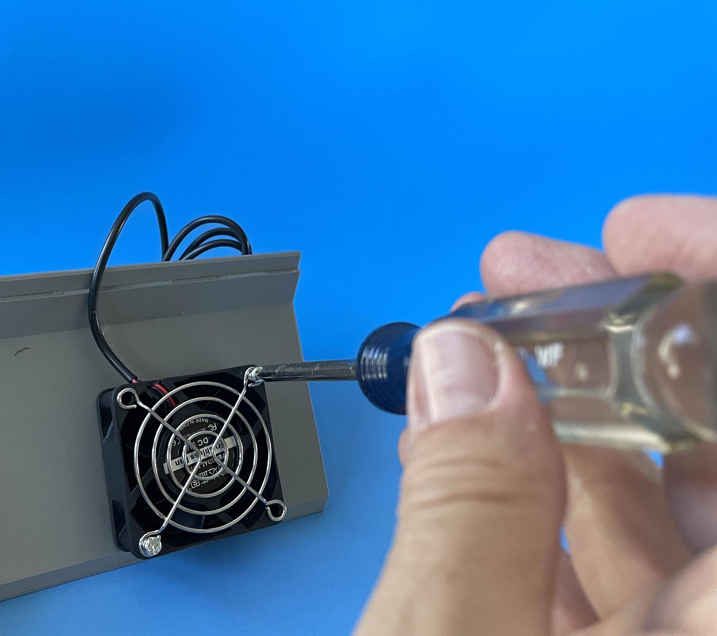
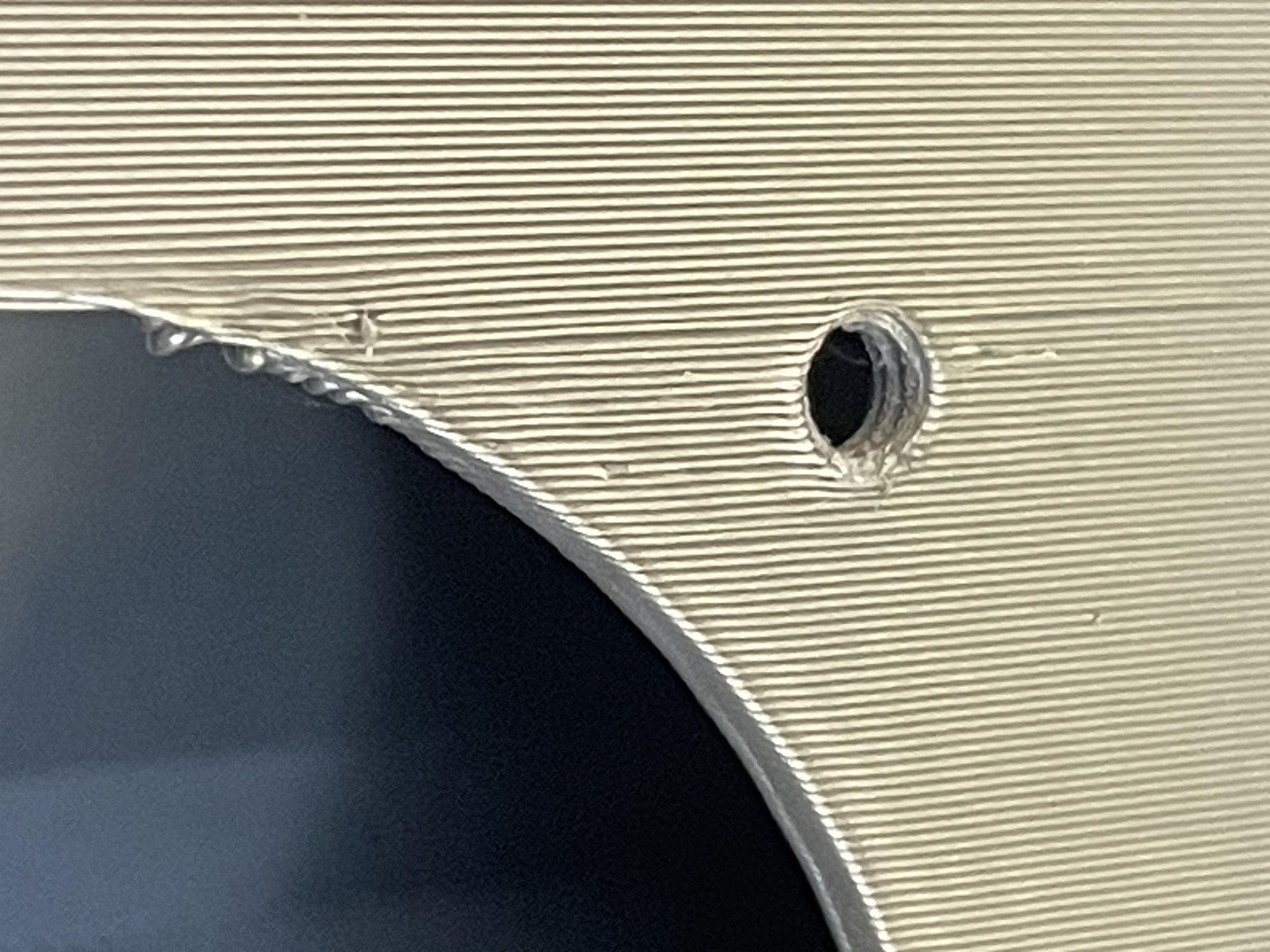
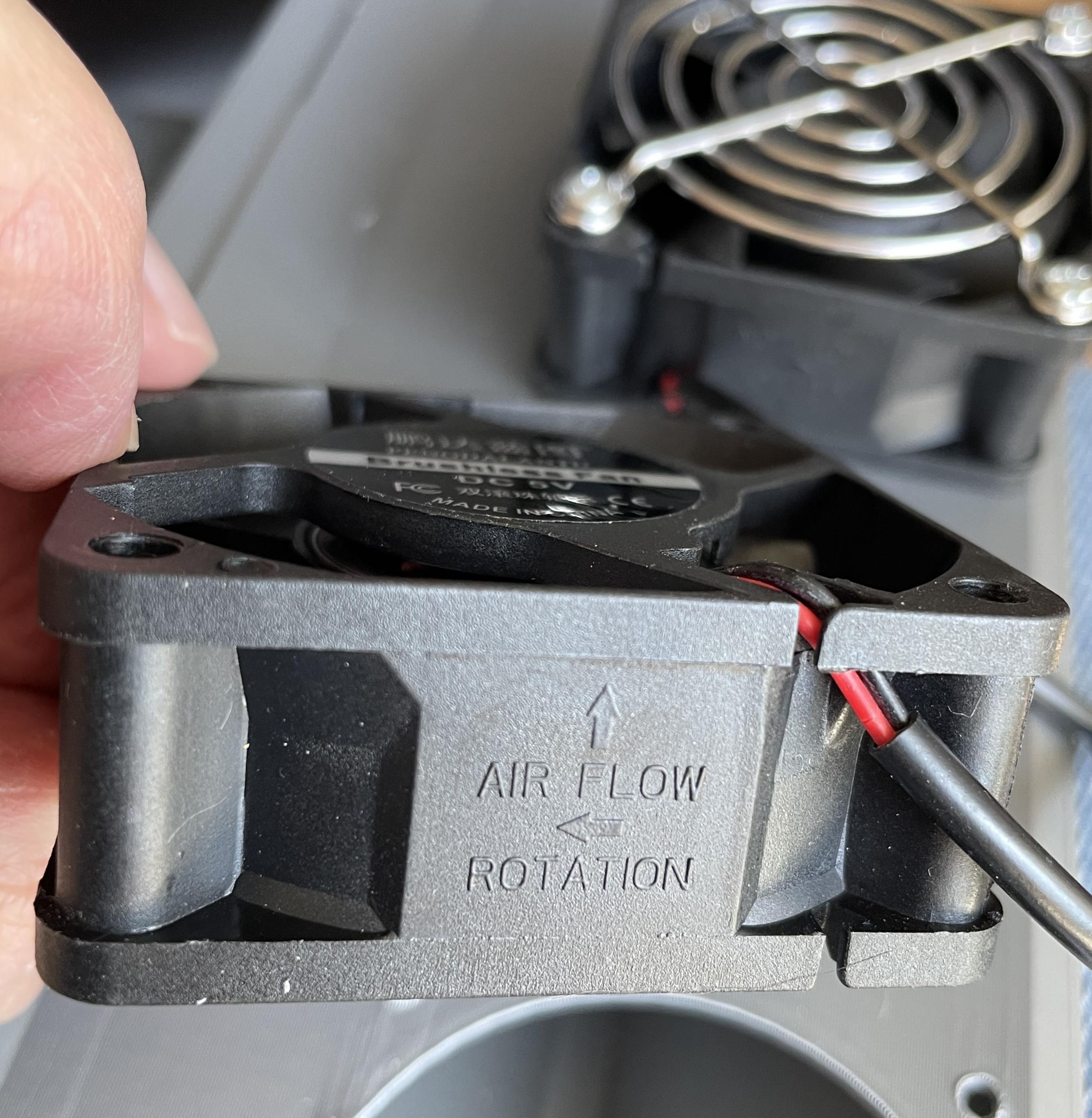
I mounted the fans using the included machine screws. I sized the mounting holes in the plastic so that the screws essentially cut their own threads.
As a side note, make sure you pay attention to the air flow direction markings on the fans. I initially mounted the fans with the air flow backwards and did not find out until the assembly was installed on the car and no hot air was being blow out. Ooops! "Check twice - mount once"!
Splice the Fan Cables Together
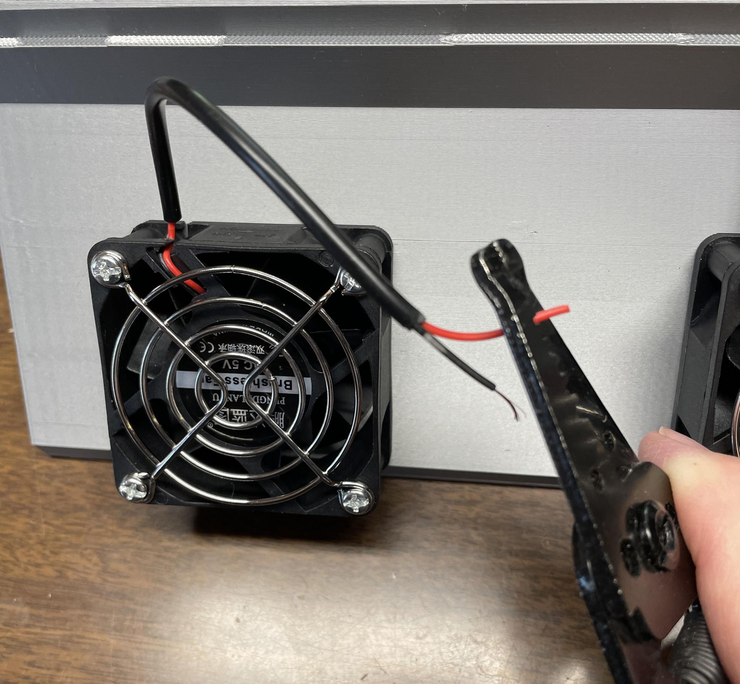
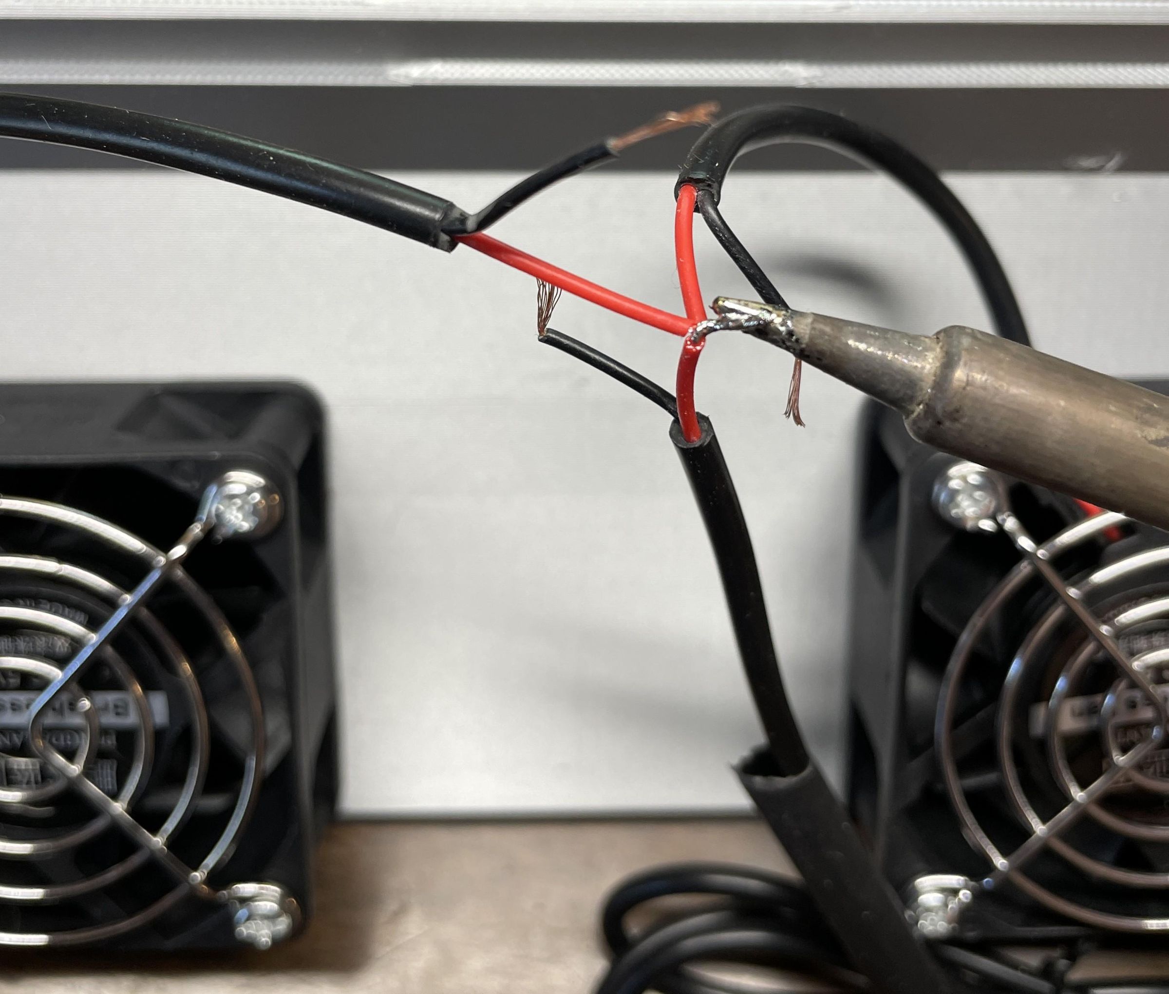
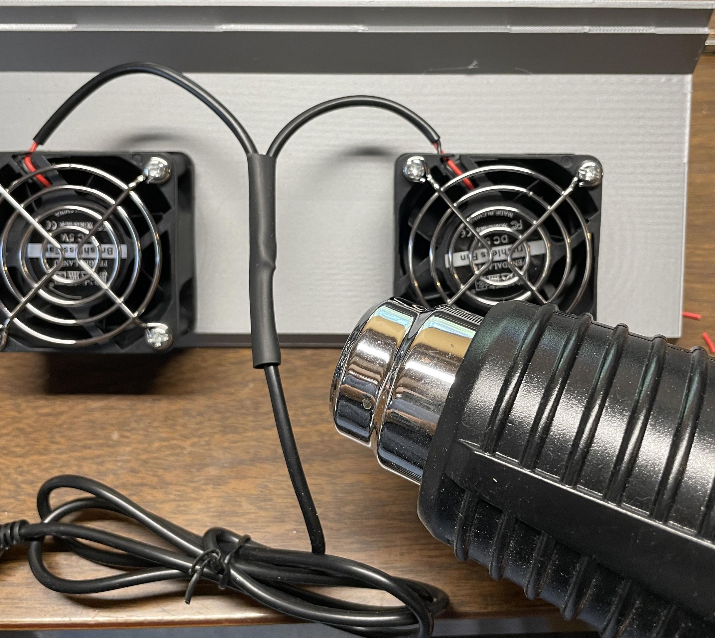
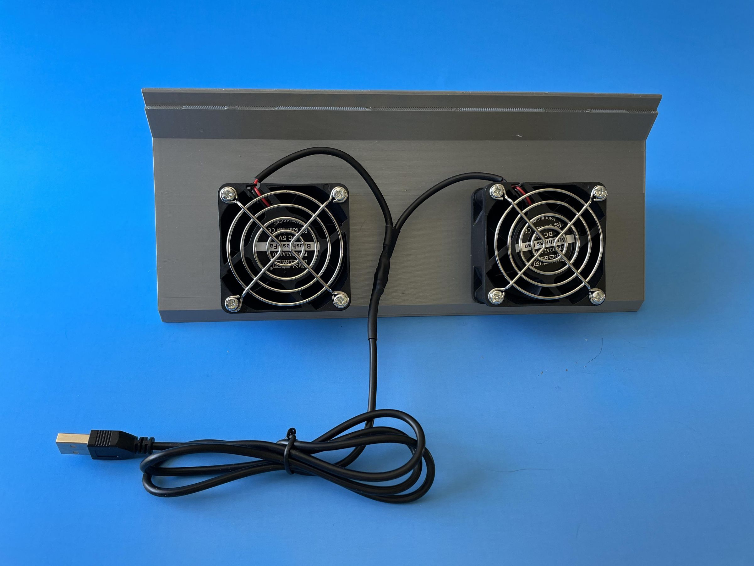
The fan cables needed to be spliced together so there was only one cable to plug into the solar panel. I cut and stripped the wires, soldered them and then covered all the splices individually and together with heat shrink tubing.
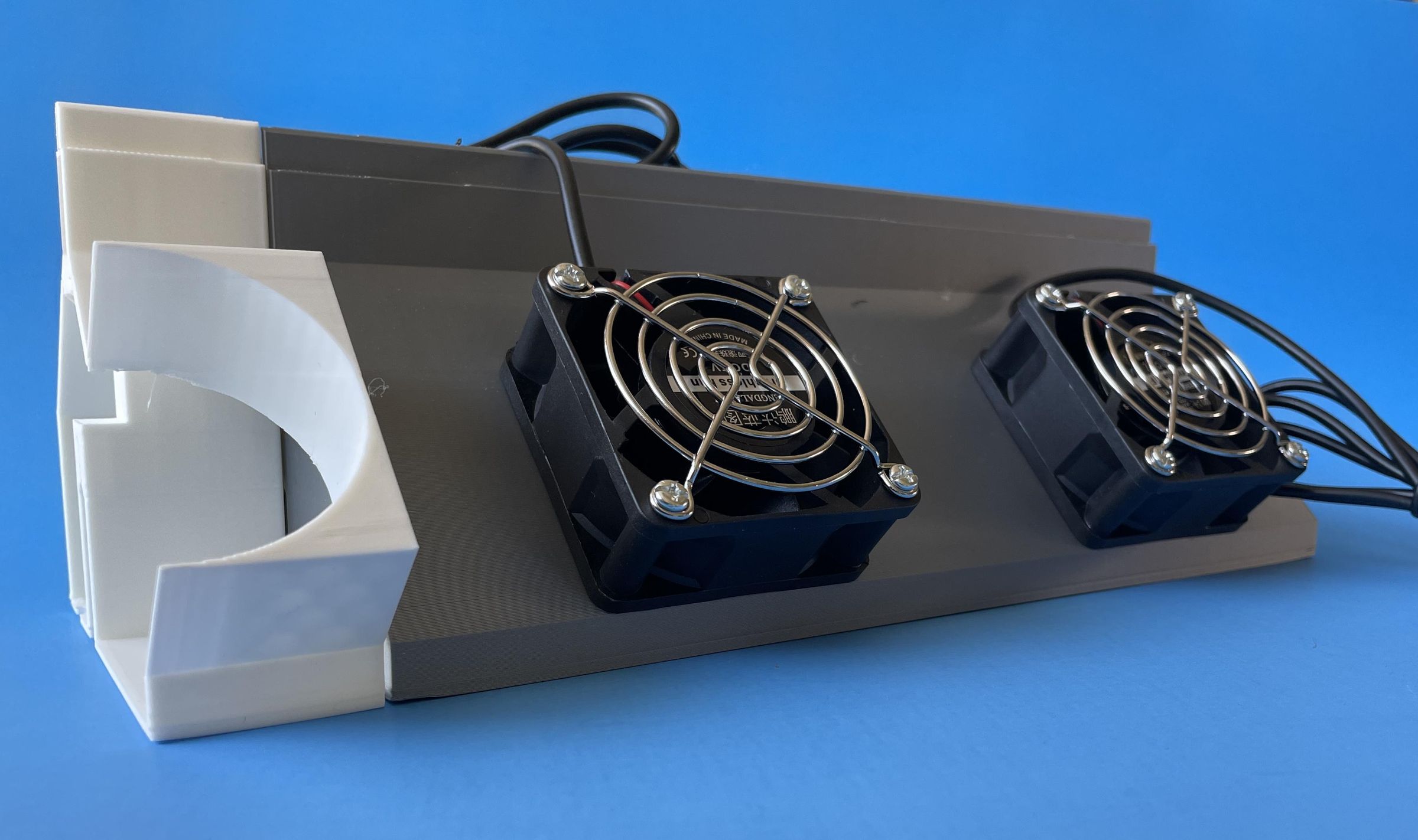
The final assembly came out looking great (Except in this photo the fans are mounted backwards blowing air into the cabin. :o lol)
Mount the Assemblies in the Window Gaps
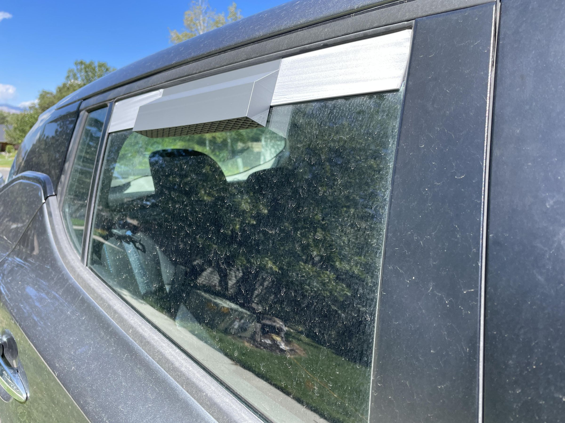
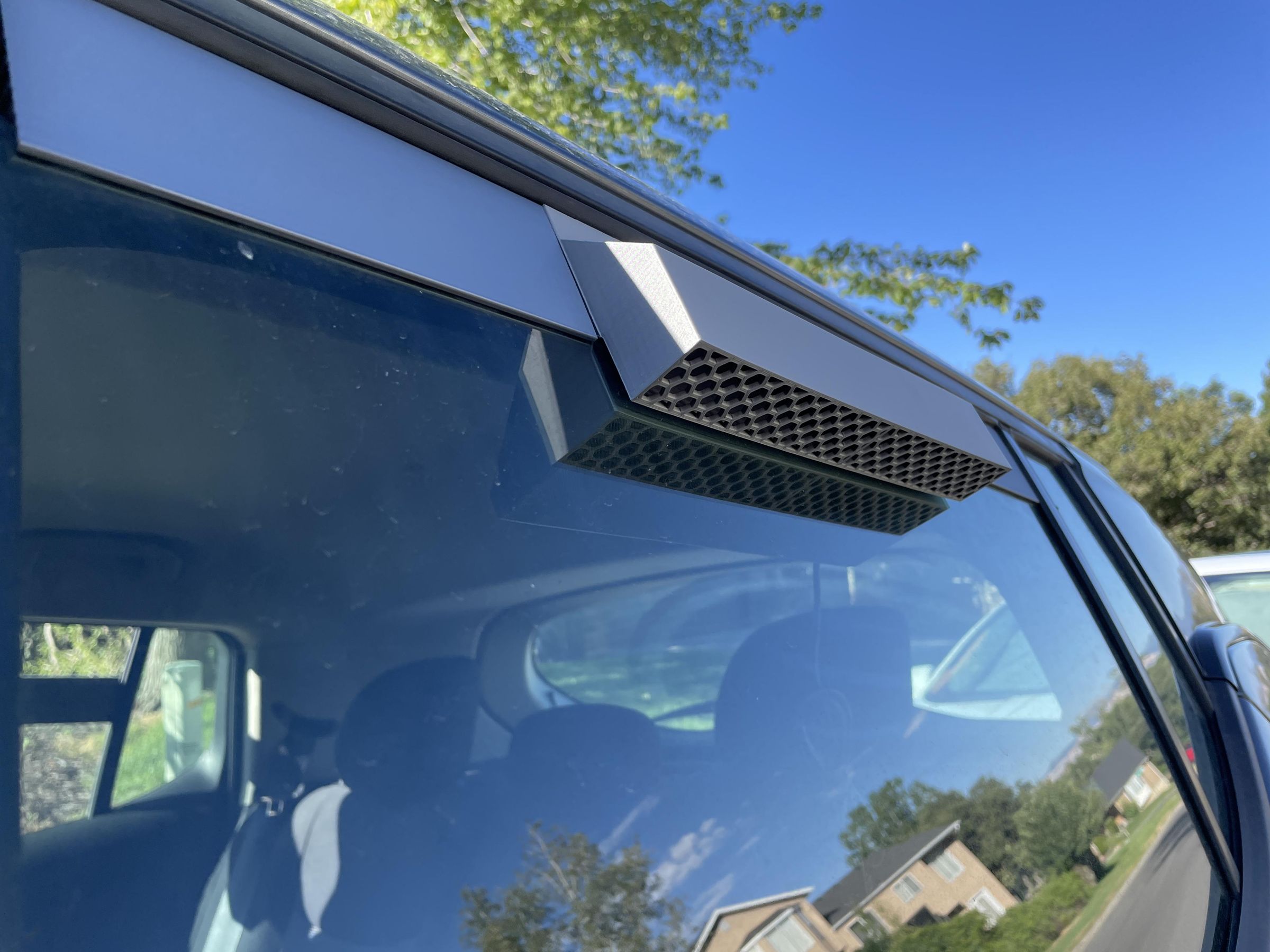
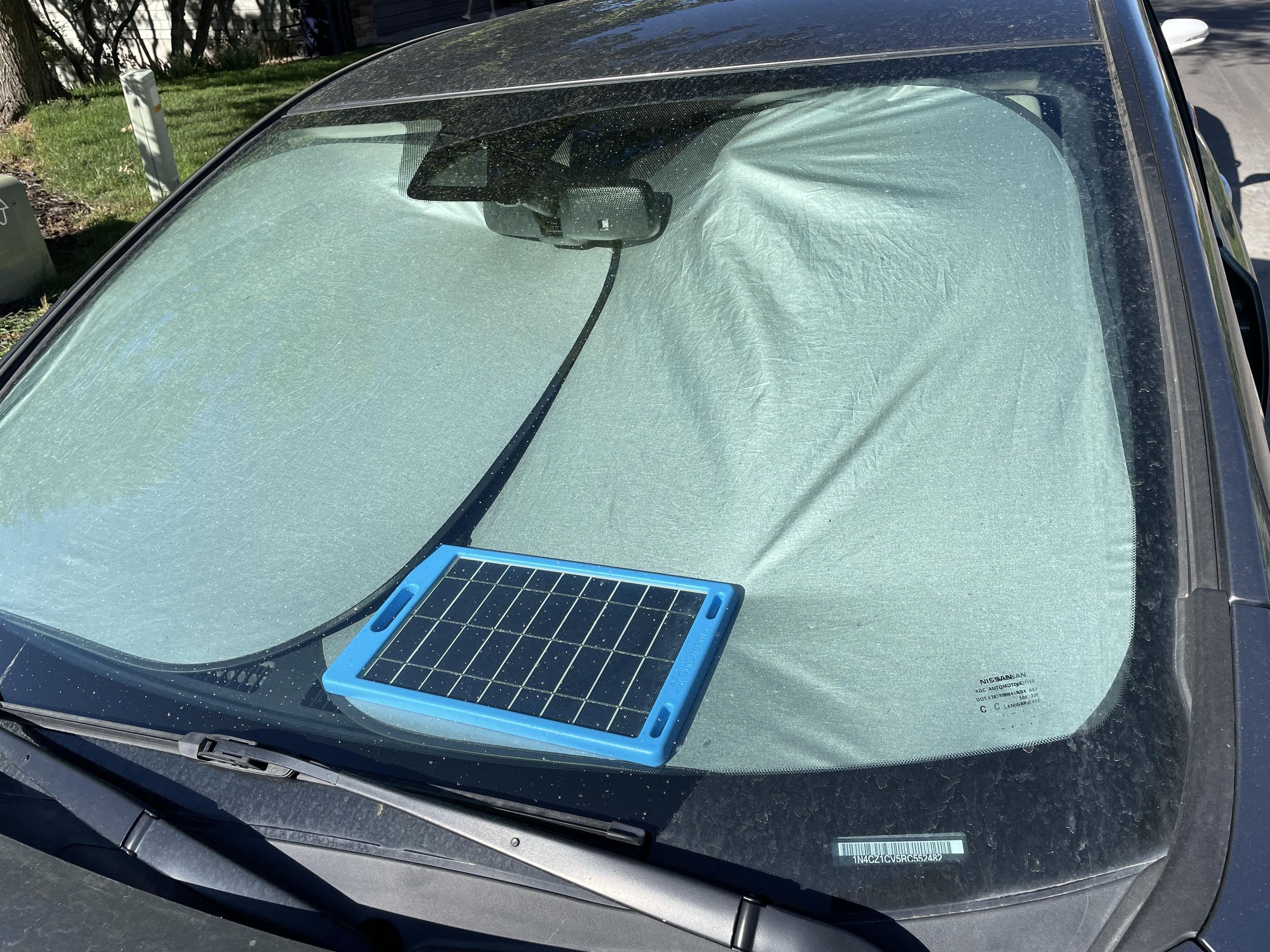
I mounted the assemblies in the car windows with the inlet on the rear passenger side and the exhaust outlet on the rear driver's side. I placed the solar panel in front of the sunshades (Actually on top of the car for my initial test). Use a USB A extension cable if needed.
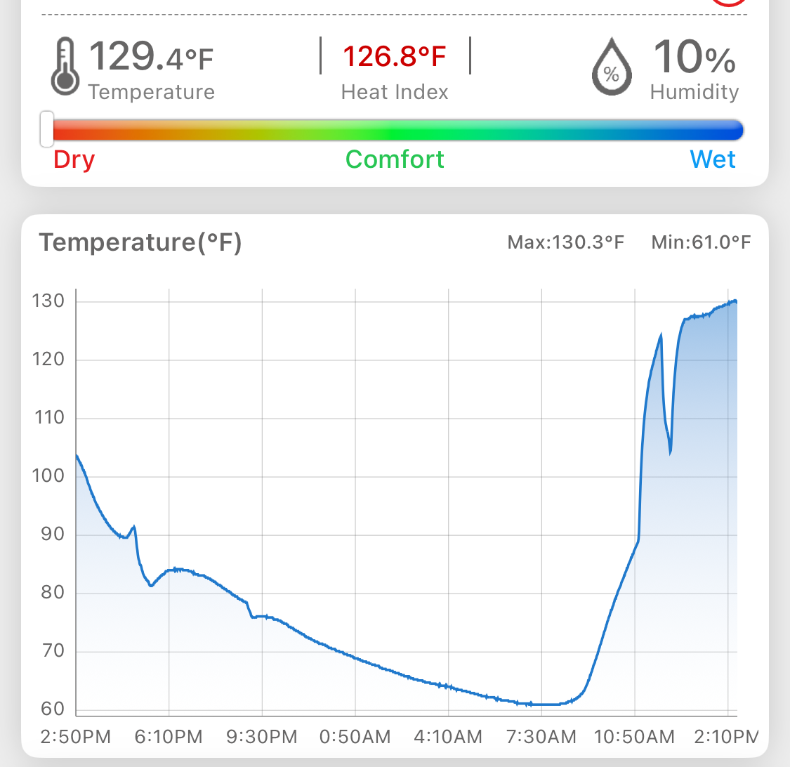
I could feel hot air being blown out of the exhaust vent. I took temperature readings and you can see the spiked drop in temperature when I opened the car to install the ventilators, followed by a sharp temperature climb (which I allowed for 30 minutes). I then allowed the ventilator to run, and the temperature started leveling off.
This test was run at midday and so the car interior was already hot.
It may not keep the car as cool as I would like, but it will certainly be much cooler than without the ventilator.
Now - No Baking Brownies in the Car!
Keep Cool and Enjoy!
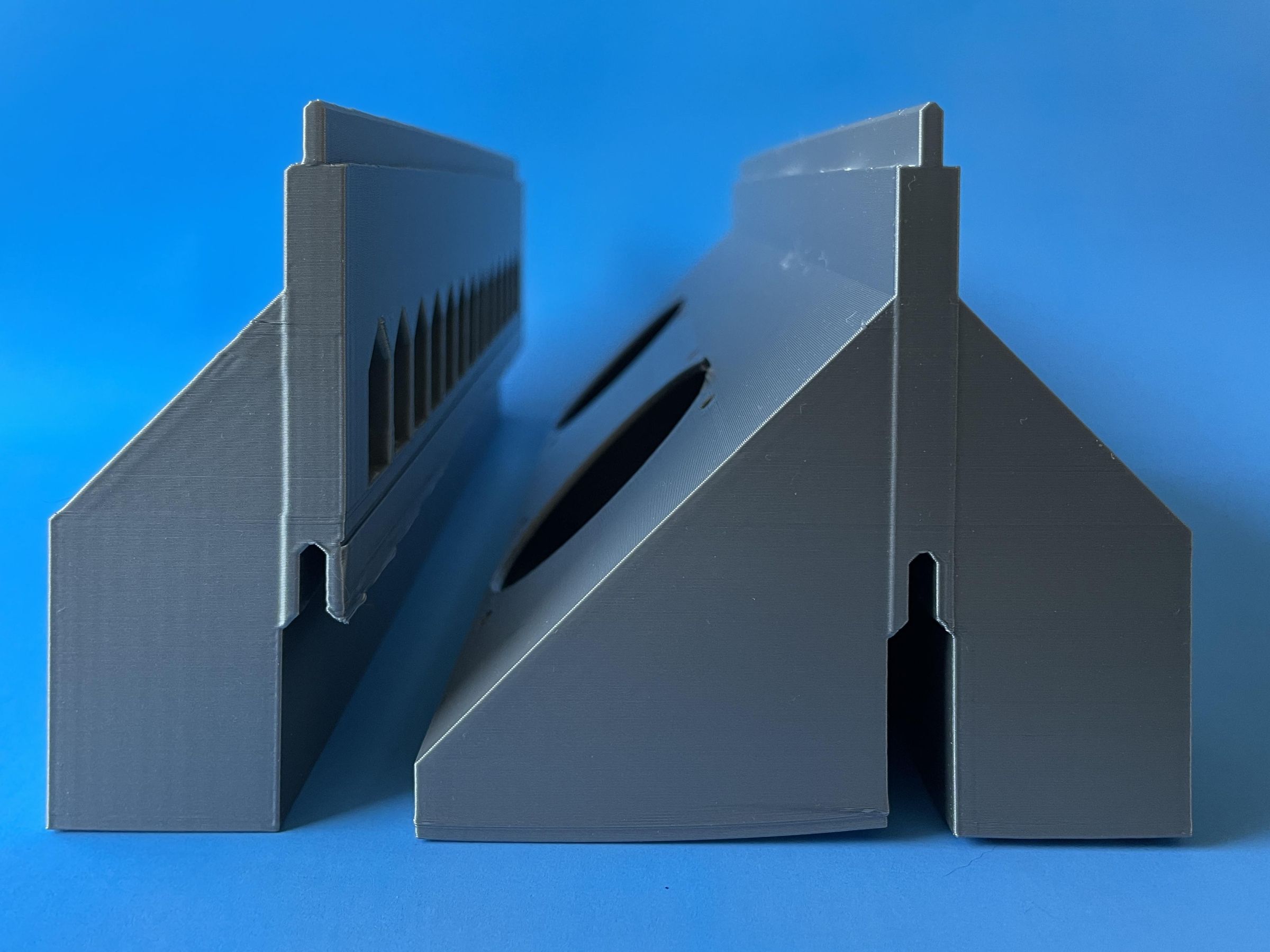
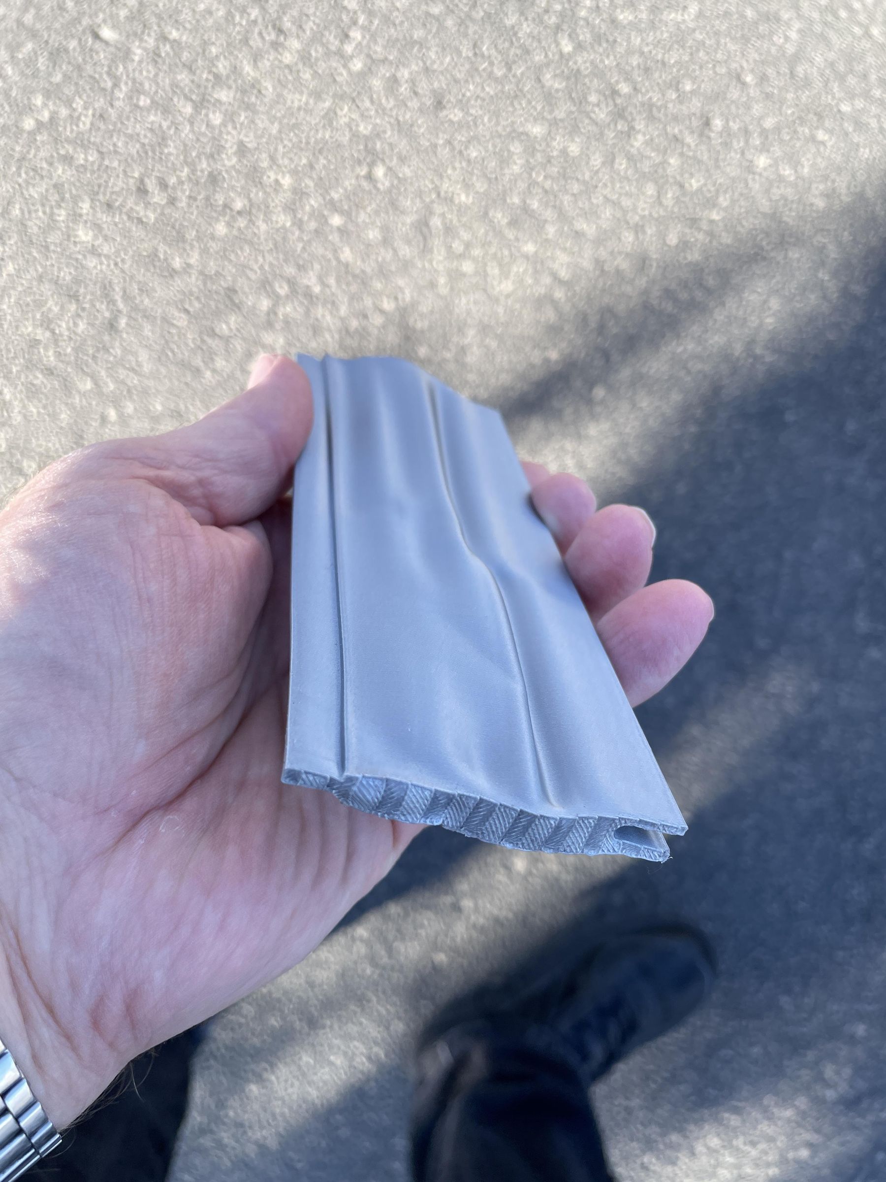
P.S. The last photo is of the filler plate that got too hot and warped. It was even slightly soft when I removed it from the car window.