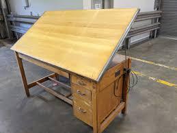
Drawing Desk


My project was an Adjustable angled drawing desk. I chose this project because I wanted something simple and functional. I also wanted to be able to do engineering drawing by hand. And although I was wrong about the easy part, I had a lot of fun with it. This project was done entirely on the CNC Router using a quarter-inch end mill. All 3d modeling was done in Fusion 360.
Supplies


Computer with Fusion 360
CNC Router
1/4" endmill
2-3 5'x8' sheets of 3/4" grade A plywood - This could be adjusted depending on how you design your legs and tabletop, such as whether you decide to weld your legs together instead.
2x drawer slides
plastic nails
2x continuous hinges
1x gate hinge or small <1in decorative hinge
Downloads
.webp)
Research


.jpeg)
Look online for inspiration. What do you want your legs to look like? What kind of mechanism do you want to use to adjust your desk's angle? originally I was just going to have the desk be one piece sitting on top of the legs with the rotating pieces on the outside. But once I realized this would make the legs too flimsy I changed my idea to more of a picture frame type leg with multiple slots for different heights. Another thing to think about is how you want to do the legs. When I first started the project I was going to use angle iron for the legs but as I got more accustomed to the router I decided to go that route.
Design
.png)


Dimension and build out your desk: This may take some troubleshooting to get the pieces to go together, such as adding tolerances and accounting for rounded angles.
One thing I very highly recommend is using dog bone joints. This will help pieces fit together properly by avoiding round inner corners. you can do this by making a line the same size as the radius at a 45* to the edge of the female part of the joint. Then make a circle the size of your tool and extrude.
My original design used angle iron for the legs but I thought better of it as the project lengthened and thought it'd be more efficient to cut out on the router although the CAD took quite a while. This also ended with a much more exact and clean looking finished product.
Prototype


cut out a prototype to see whether your joints fit together smoothly. I didn't do this cause I'm dumb but you should. At first, I didn't know how to do dogbone joints and was just going to add tolerances to all the joints I already had but once I learned how I realized how much smother it made everything. Another thing prototyping helped me find out was the thickness of material I wanted to use. I originally used tenth-inch stock but it was way too thin which I realized after cutting out a prototype. I did my rough sketch in cad just roughly putting together what I wanted the desk to look like and how I wanted it to function. I also made a prototype of the desk legs using lower-grade plywood before using nicer plywood.
Downloads
Redesign


Once you complete your prototype use what you learn to redesign your model to improve your final product. After cutting out my prototype drawer out of .1" stock I realized how flimsy the material was and ended up completely scrapping the model and the prototype, redesigning it with 3/4" plywood. I also realized that the joints I had created wouldn't fit together due to the rounded corners which led me to using dog bone joints.
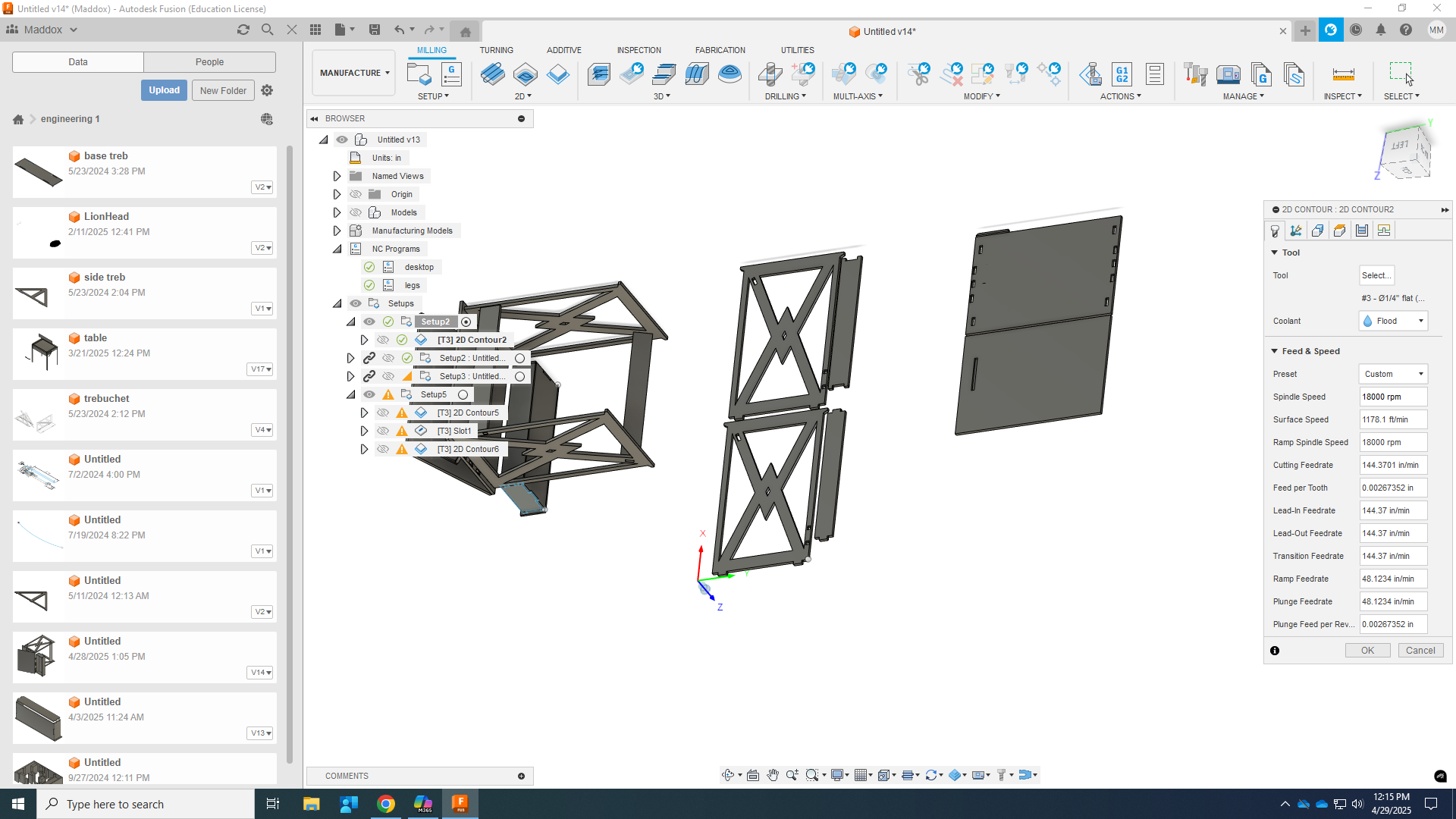
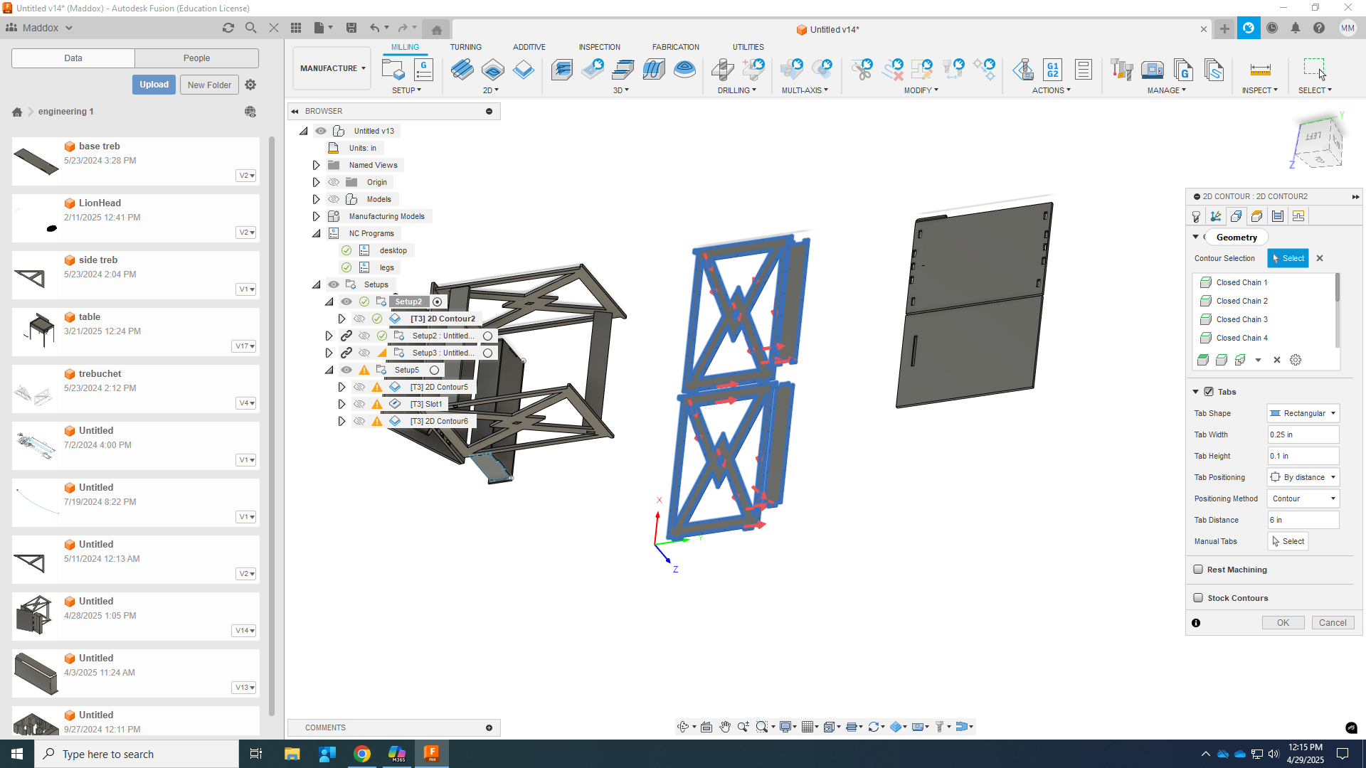
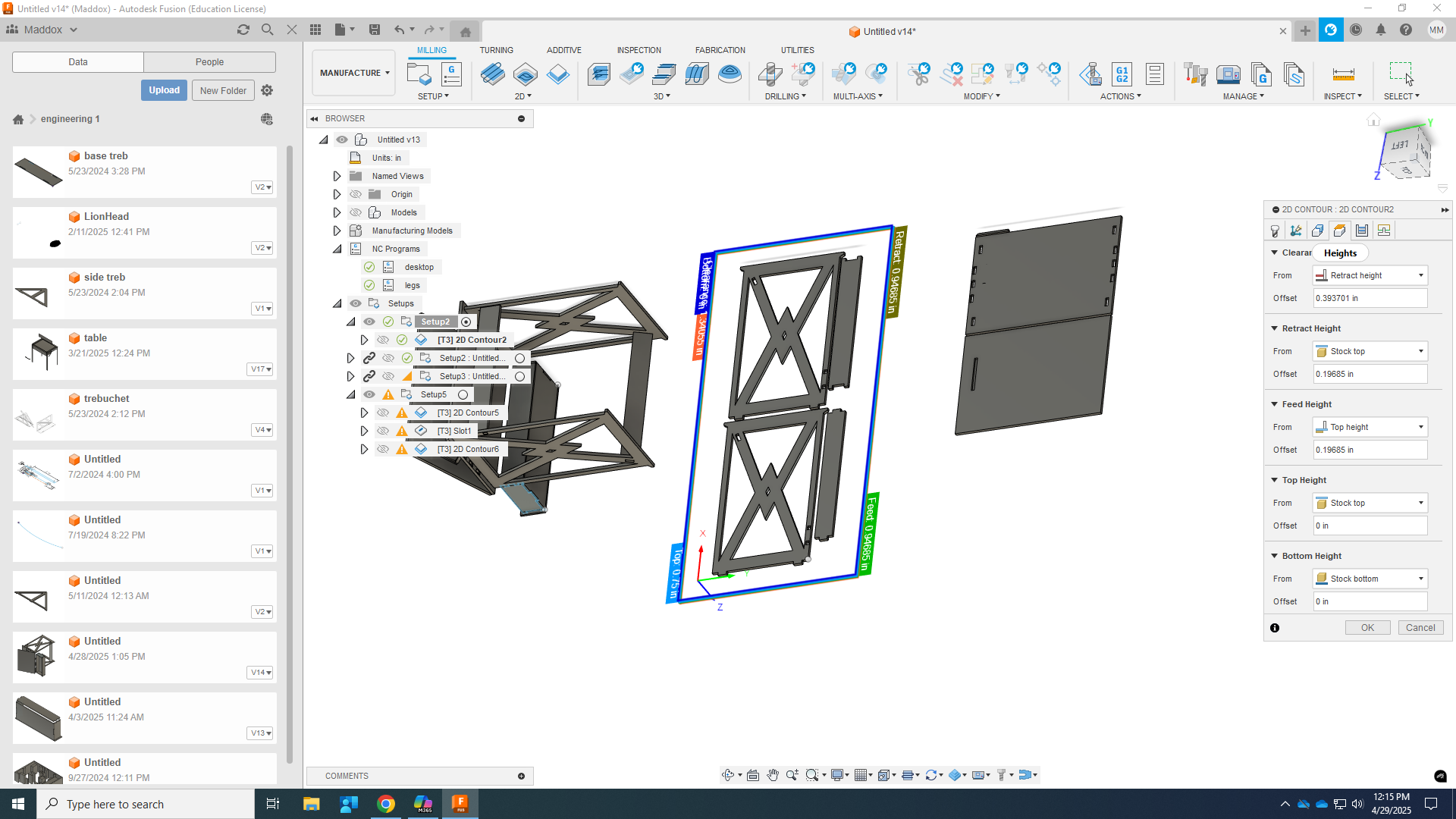
CAM
.png)
.png)
.png)
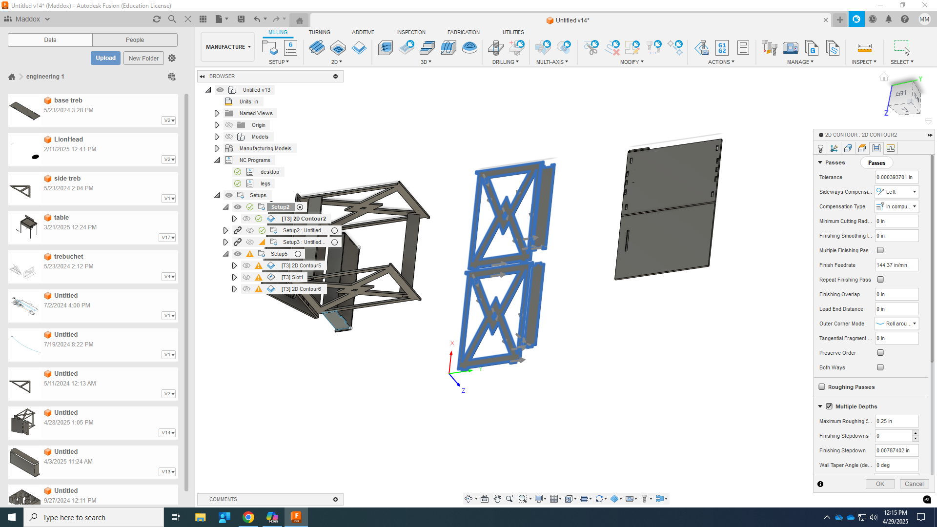.png)
create a manufacturing model
select edit manufacturing model, select the bodies you want to cut out, place them out flat using the arrange tool. While arranging try and place your pieces in as small of a space as possible to save material.
In the top left go back to manufacturing
create a 2D contour, and 2d adaptive clear
For All:
set spindle to 18000 rpm
set cutting feed rate to 144in/min
select contours in geometry
select multiple depths/put maximum roughing stepdown as your tool diameter
For contour:
enable tabs I usually set them too small so I'd say make them about a quarter inch wide and .15" tall
set your heights - set your bottom height to your stock bottom and your top height to your stock top, you don't normally have to worry about the other heights for the router.
select multiple depths/put maximum roughing stepdown as your tool diameter
ignore linking
For Adaptive Clear:
Select the pockets you want to clear in geometry
set your heights to bottom at your selected contours and top at stock top
for Linking set stepdown to plunge instead of spiral, this isn't necessary but it is a time saver
All:
once that's all done check your model to make sure you cut all the way through and there are no errors.
create an NC program by pressing the button in the top left hand corner, rename your file and go to post-processing select your setup and your processes. then post it to your usb.
Cut Out


Put USB into router
Nail down plywood
set origin F11.55
grab tool F31.3
click file button
select your file
warm up spindle with green button on keypad
click ok
turn on vacuum
be ready to pause
dismount part - make sure while dismounting not to break the edges of your part or snap more fragile pieces
Assemble


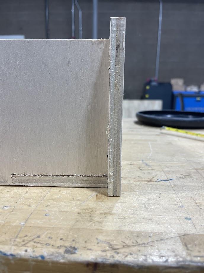(3).jpg)


use a soft mallet to wedge your pieces into place for added security you can use wood glue or nail pieces together. One problem I had was due to the lower half of the table top having to be made out of two separate pieces because I didn't have enough material the pieces didn't line up perfectly. Another problem is When building the drawer I made it too wide and it caused the drawer slides to lock up which could be easily avoided in the future. Also the nails I used to secure the bottom of the drawer split the plywood a little but which put a damper on the looks of the drawer.
Bask in Your Success

.jpg)
https://a360.co/3EJwuvW
There are plenty of other things you can do to improve upon it. Such as staining it with polyurethane and sanding down slash wood-filling lots of the imperfections.