Drawing Robot - Wifi Bluetooth USB CNC Shield Grbl_Esp32
by bluino_electronics in Workshop > CNC
10368 Views, 23 Favorites, 0 Comments
Drawing Robot - Wifi Bluetooth USB CNC Shield Grbl_Esp32

The Drawing Robot is a simple pen plotter. All of the custom parts are 3D printed. The rest of the parts are low cost and easy to get. The controller uses an ESP32 running Grbl_ESP32 firmware. It can be controlled via USB, Bluetooth or Wifi. You can simply upload gcode files to the unboard SD card and print.
The machine is controlled by a unique H-bot configuration, that uses a single belt. Two Nema17 stepper motors drive that belt in a special way to move in the X/Y plane. The pen is lifted by a hobby servo MG90/SG90 using a very simple and accurate mechanism.
The Drawing Robot based on open source project by bdring, many thanks for develop this project. You can find all the firmware code Grbl_ESP32 in Github repo.
Supplies

- 1x X Motor Support Acrylic
- 1x Y Motor Support Acrylic
- 1x Frame Cover Acrylic
- 1x Left Egg Holder 3D Printed Part
- 1x Right Egg Holder 3D Printed Part
- 1x Cap Support 3D Printed Part
- 1x Vertical Y Arm 3D Printed Part
- 1x Pen Holder 3D Printed Part
- 1x Drawbot Holder Support 3D Printed Part here
- 4x Spacer 3mm 3D Printed Part
- 1x V-slot Frame 2060 15cm
- 1x Controller ESP32 Drawing Robot Shield
- 2x Stepper Motor Nema17
- 1x Servo SG90
- 1x MicroSD 8GB
- 1x Bearing 693ZZ
- 1x Power Supply Adaptor 3A 8V
- 1x Linear Rod Dia.3mmx100mm
- 1x Press Spring
- 1x Knob M3
- 4x M5x6mm Hex Socket Screw
- 2x M5x8mm Hex Socket Screw
- 1x M5x12mm Hex Socket Screw
- 4x M3x8mm screw
- 8x M3x6mm screw
- 1x M3x25mm screw
- 1x M3 Nut
- 1x M2x10mm screw
- 1x M2 Nut
- Marker
Circuit Diagram Drawbot

Schematic.
Part List of Shield
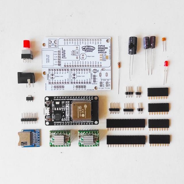
Part List of ESP32 Drawing Robot Shield:
- 1 x PCB ESP32 Drawing Robot Shield
- 1x ESP32 DEVKIT V1 board
- 2x Driver Stepper Motor A4988
- 2x Micro-SD Adapter module
- 1x LED 3mm
- 2x V-Regulator 5V AMS1117 (SMD)
- 1x Resistor 10K Ohm
- 1x Capacitor 0.1uF
- 2x Capacitor 100uF/16V
- 1x Capacitor 1000uF/16V
- 1x DPDT Lock Switch 8.5x8.5mm
- 1x Barel Socket DC
- 2x Female Header 15 pin
- 4x Female Header 8 pin
- 2x Male Header 4 pin
- 1x Male Header 3 pin
- 2x Male Header 2 pin
PCB (PCBWay)
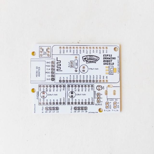
This article is proudly sponsored by PCBWAY.
To make this project you need to order a prototype PCB on PCBWAY. How to order is very easy and you will get 10 Pcs PCB for $5 with very great PCB quality.
Step to Order:
1. SignUp/Log in on pcbway.com
2. Open this PCB project link ESP32 Drawing Robot Shield
3. Click Add to cart.
4. Wait moment for PCB review, then Click Check Out.
Soldering SMD & MicroSD Module


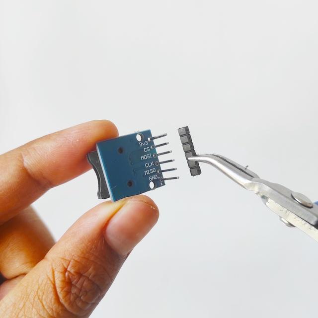
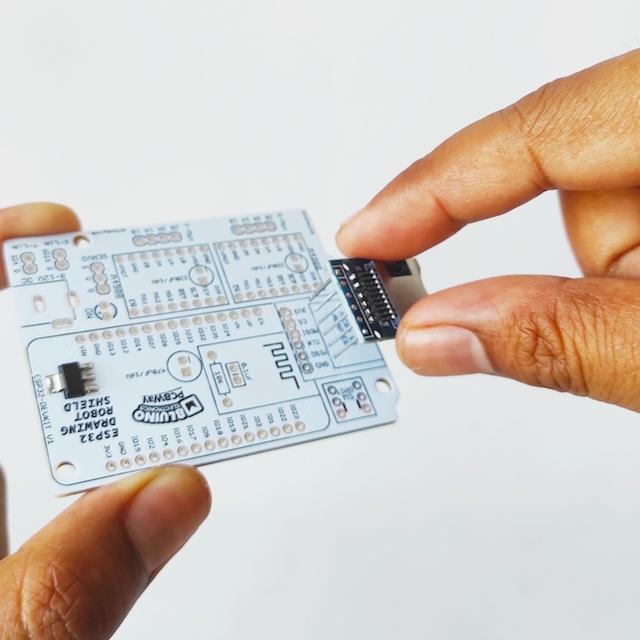
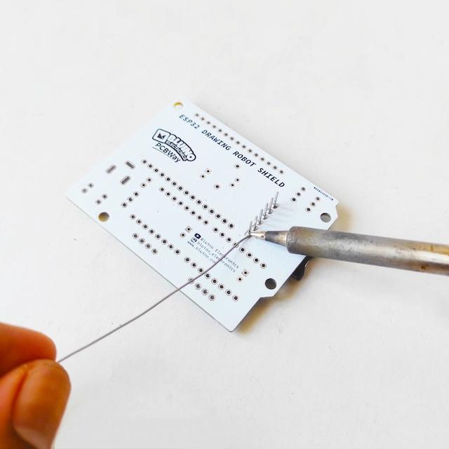

- This shield has one SMD component, it is not too difficult to solder because the size of the SMD component is quite large, so don't worry. You will need tweezers as a tool to hold the components when soldered.
- Solder 8 pin male header to microSD adapter module.
- Remove plastic holder use pliers.
- Attach microSD adapter with male header soldered to PCB.
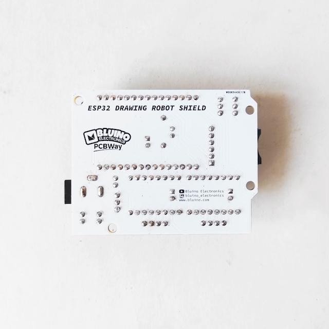
- Solder pins male header on the back of PCB.
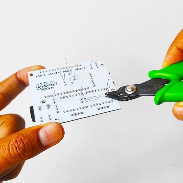
- Cut the long legs male header.
Soldering Components
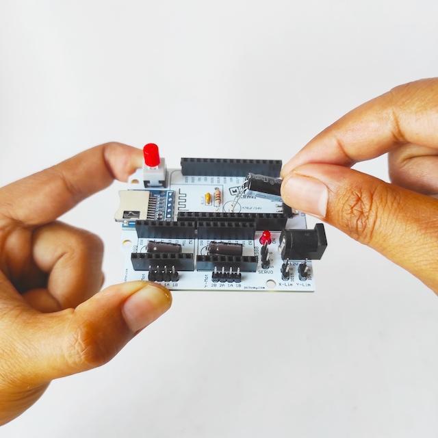
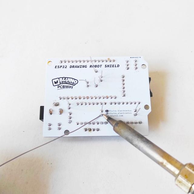
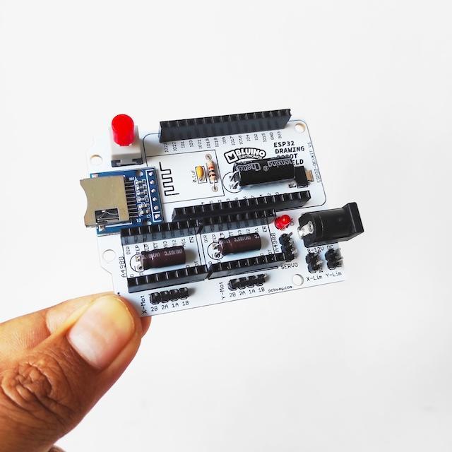
- After finish solder SMD component and microSD adapter, next attach other trough hole components on the PCB following the pictures and symbols on the PCB.
- Solder all the component legs on the back of the PCB.
- Cut all the long legs of the component wire.
- Shield already finished solder
Attach Modules


- Attach the ESP32 board and two Driver Stepper Motor A4988 into the female header socket as shown, look at the pin name dont get the wrong orientation.
Holder X Motor
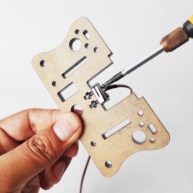
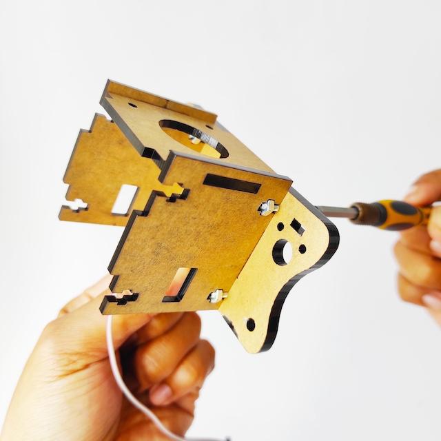


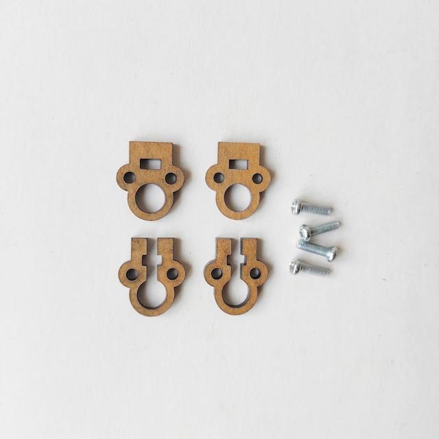
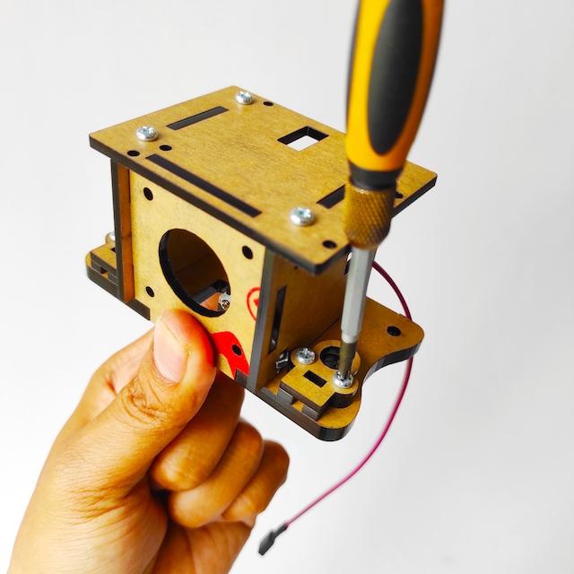

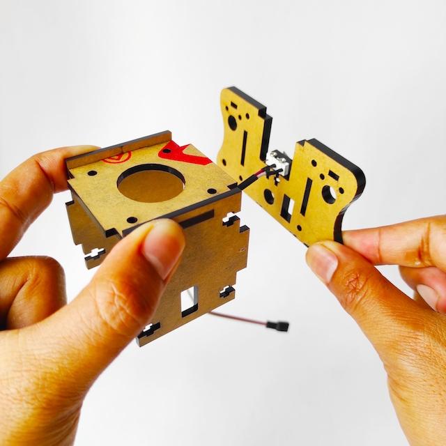
Prepare parts as below:
- Acrylic Parts
- X limit switch
- 8x M3 12mm
- 8x Nut M3
- 2x M2 12mm
- 2x Nut M2
- Install and tighten the X limit switch that has a soldered cable using 2 M2x12mm screw as shown below.
- Attach acrylic set for motor holder into 5mm base acrylic.
- Tighten use 4 M3x12mm screw.
- Attach acrylic base for shield holder.
- Tighten use 4 M3x12mm screw.
- Prepare Acrylic Parts and 4 M3x10mm.
- Stack two stoppers on the left and right 5mm base acrylic, then tighten use 2 M3x10mm screws.
Holder Y Motor
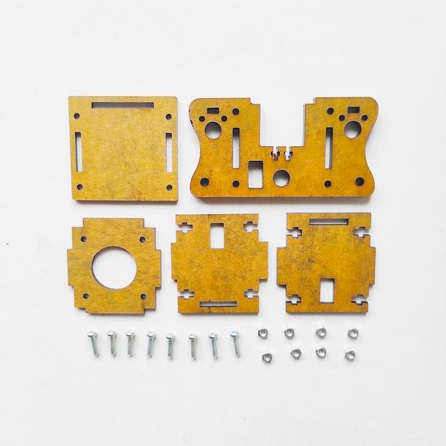
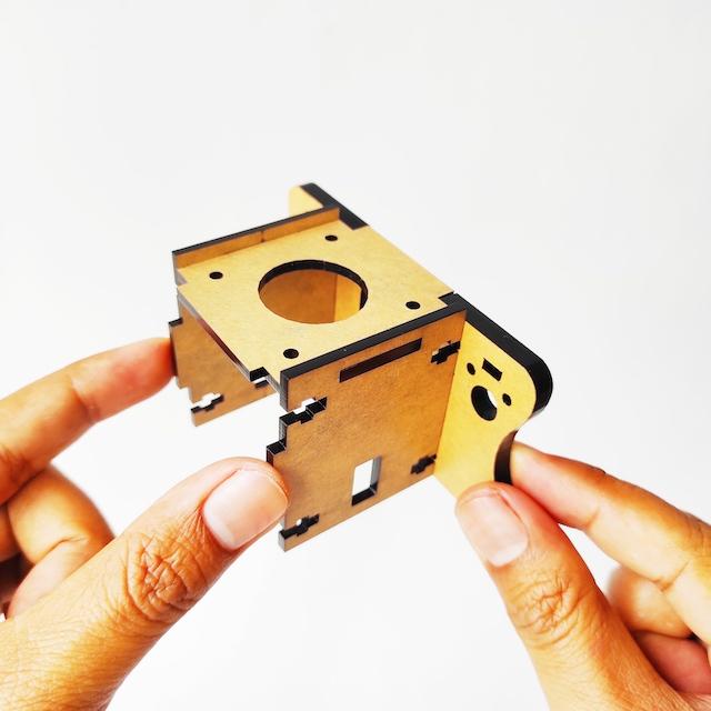

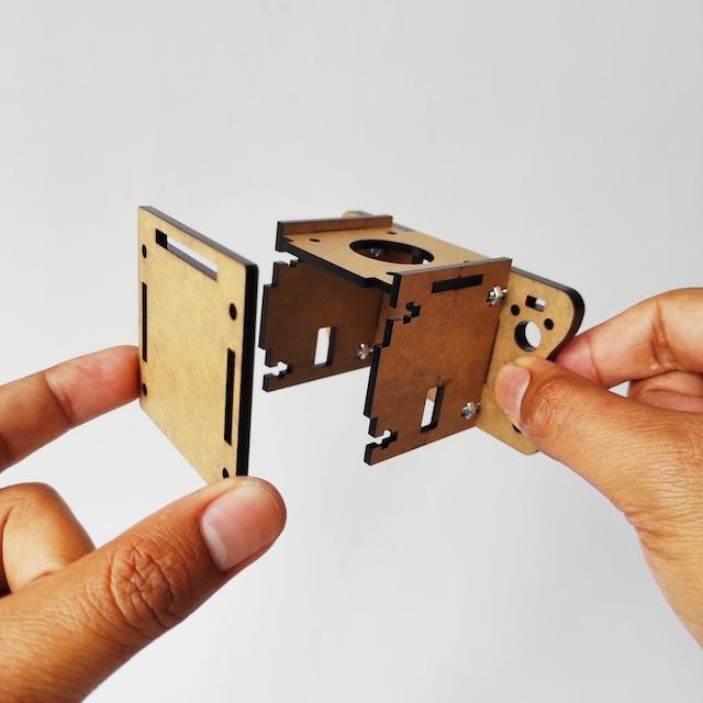
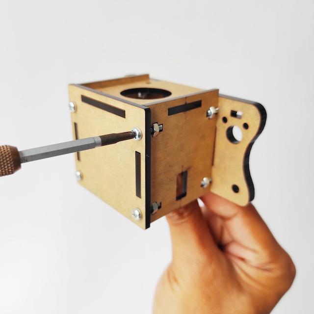


Prepare parts as below:
- Acrylic Parts
- 8x M3 12mm
- 8x Nut M3
- Attach acrylic set for motor holder into 5mm base acrylic.
- Tighten use 4 M3x12mm screw.
- Attach cover acrylic.
- Tighten use 4 M3x12mm screw.
- Prepare Acrylic Parts and 4 M3x10mm.
- Stack two stoppers on the left and right 5mm base acrylic.
- Tighten use 2 M3x10mm screws.
- Two XY holder motor are ready.
Back Support
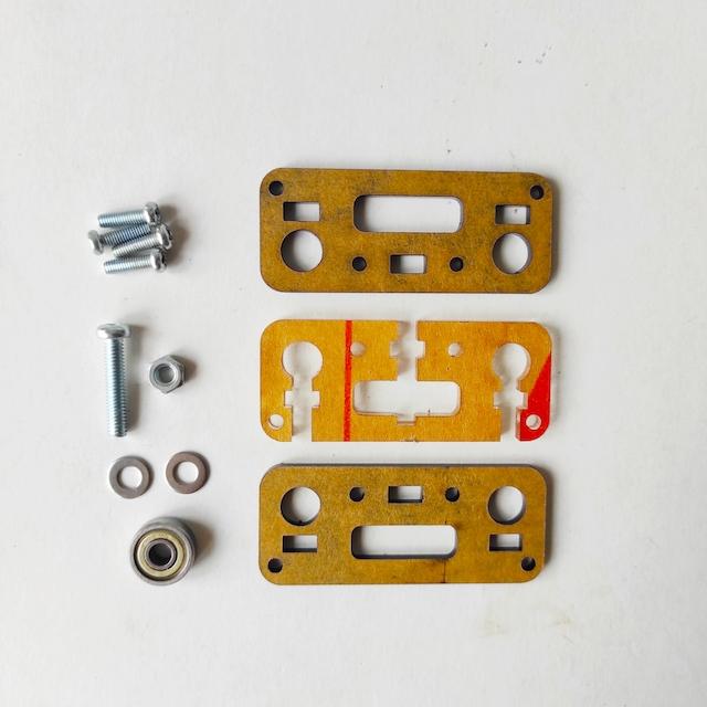
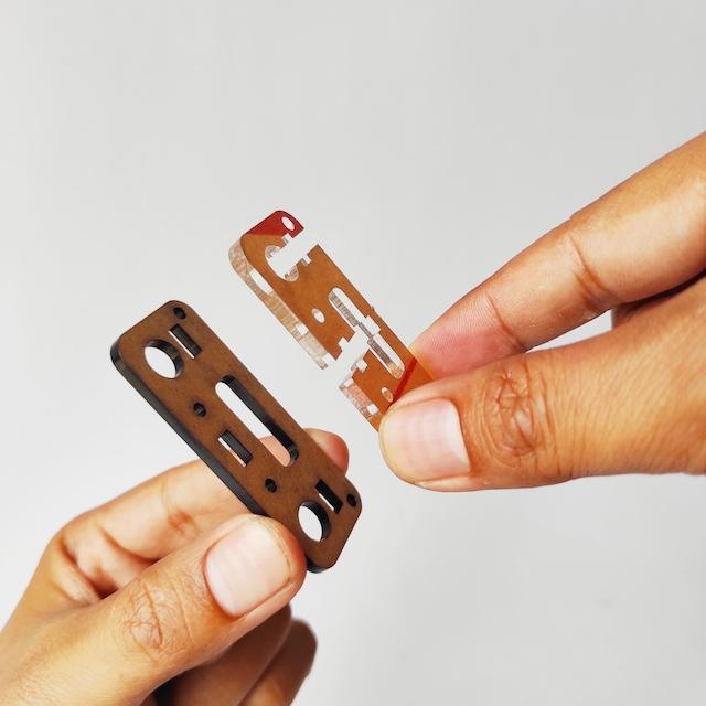
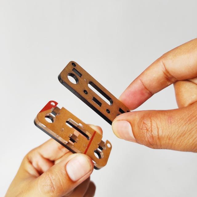

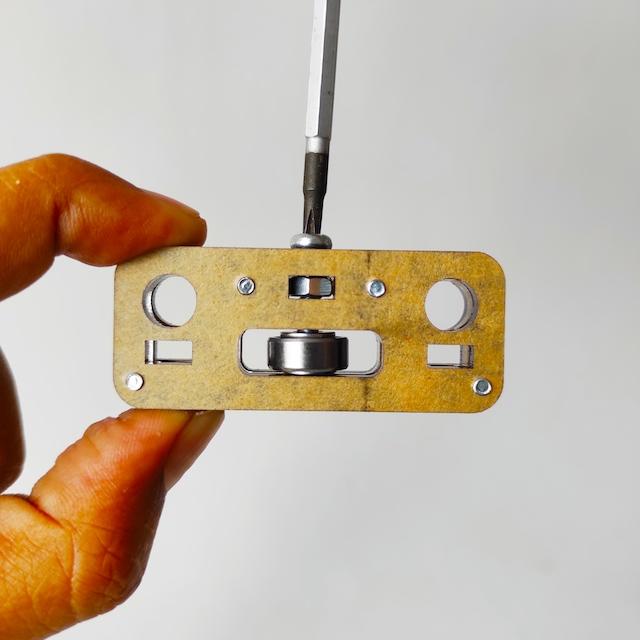
Prepare parts as below:
- Acrylic Parts
- Bearing 624ZZ
- 4x M3 10mm
- 1x M4 20mm
- 2x Washer M4
- 1x Nut M4
- Stack the first and second acrylic parts as shown below.
- Next, stack the third part of the acrylic.
- Tighten use 4 M3x10mm screws.
- Insert the bearing into the acrylic hole with clamped by 2 washers, then insert the M4 20mm screw as shown below.
Front Support
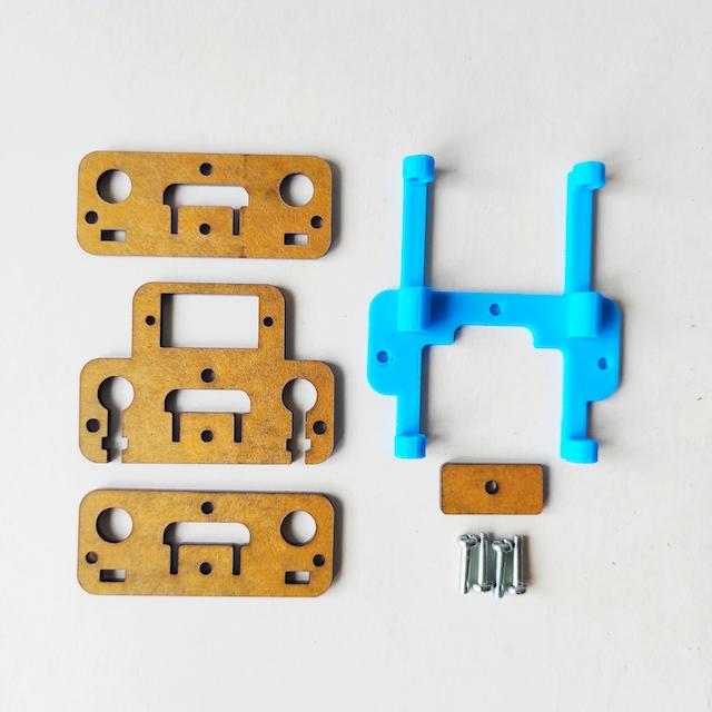
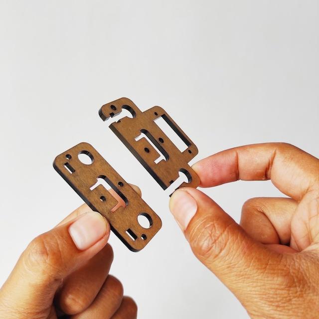

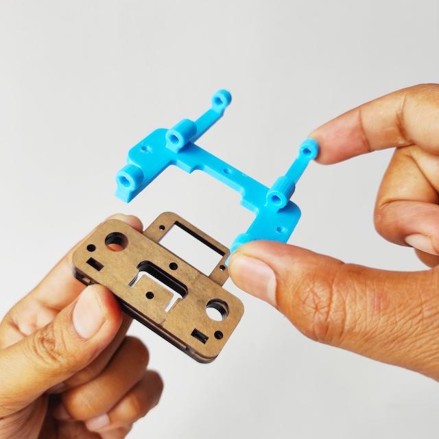

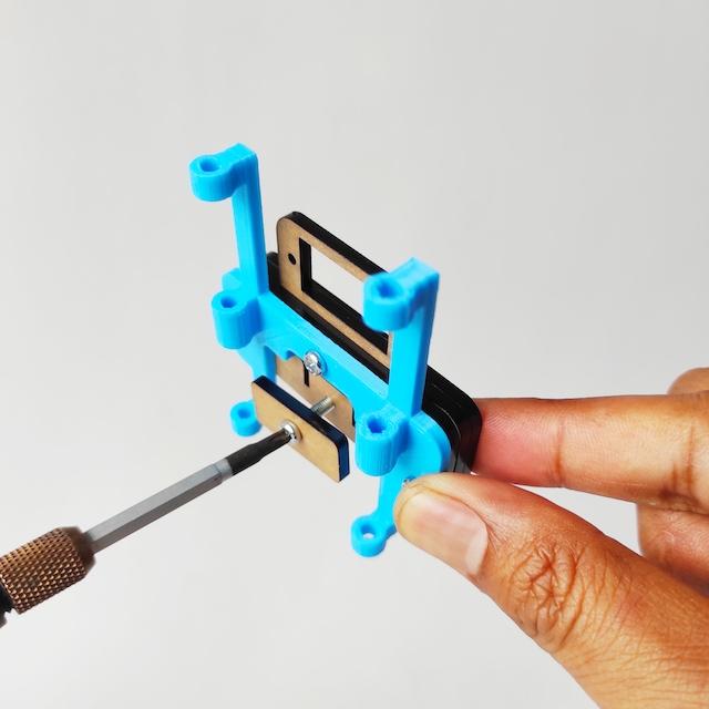
Prepare parts as below:
- Acrylic Parts
- 3D Printed Support
- 4x M3 12mm
- Stack the first and second acrylic parts as shown below.
- Then stack the third part of the acrylic.
- Last, stack the 3D Printed Support.
- Tighten use 3 M3x10mm screws.
- Attach the acrylic part as a belt stopper, use M3x10mm screw but dont tighten it.
Pen Holder
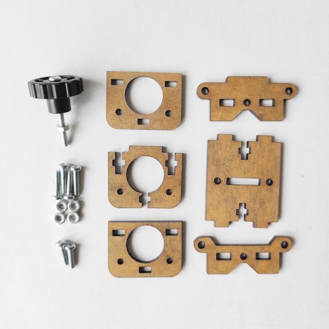
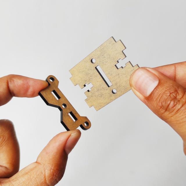


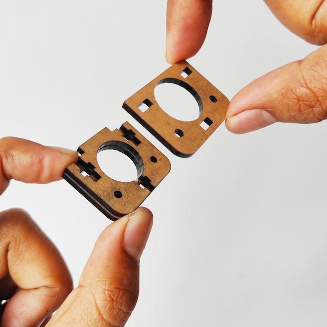
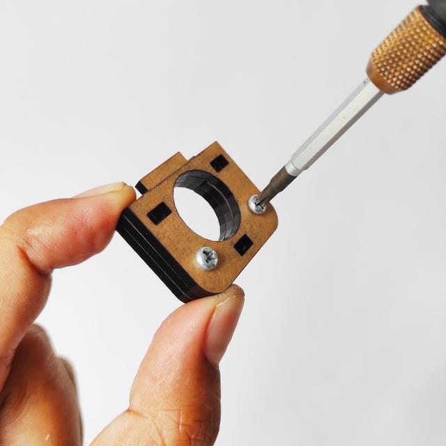
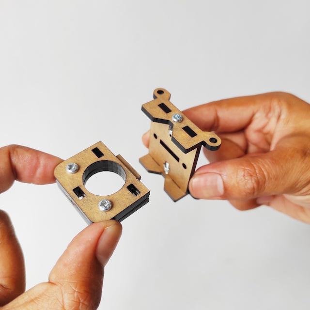

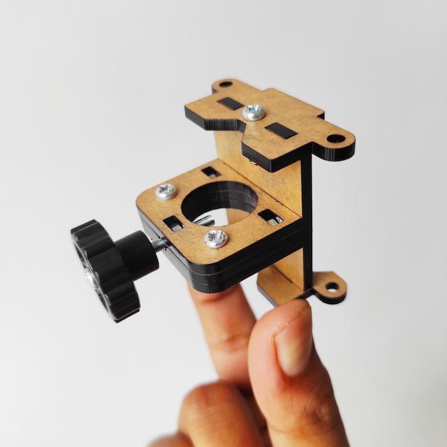
Prepare parts as below:
- Acrylic Parts
- Knob M3x25mm
- 4x M3 12mm
- 4x Nut M3
- 2x M3 10mm
- Attach two acrylic part as shown below.
- Tighten use M3x12mm screws.
- Also on the top, attach it and then tighten it.
- Stack three acrylic pieces as below.
- Tighten use 2 M3x10mm screws.
- Attach acrylic asy with other shown as below, then tighten use 2 M3x12mm screw.
- Install knob that is usefulfor holding pen as shown below.
- Done, Pen Holder is ready.
Bottom Slider Holder
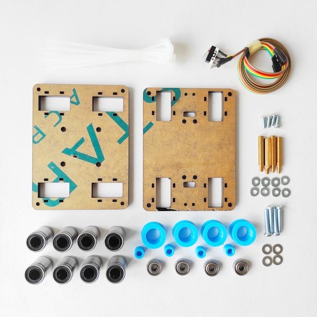


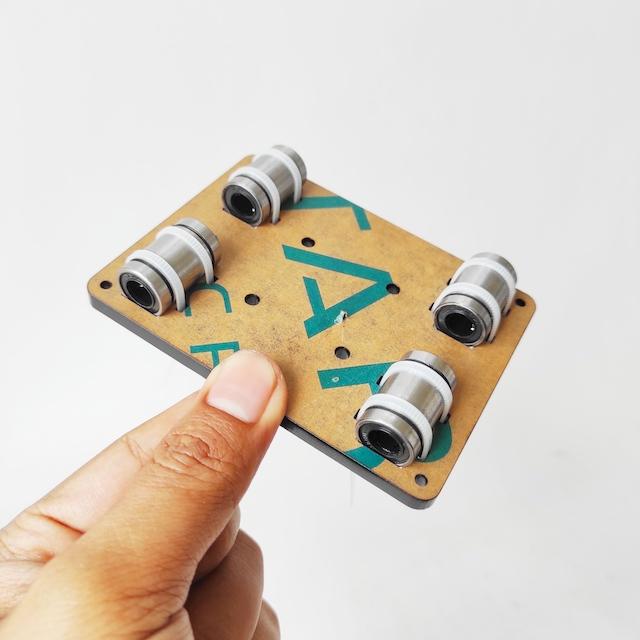
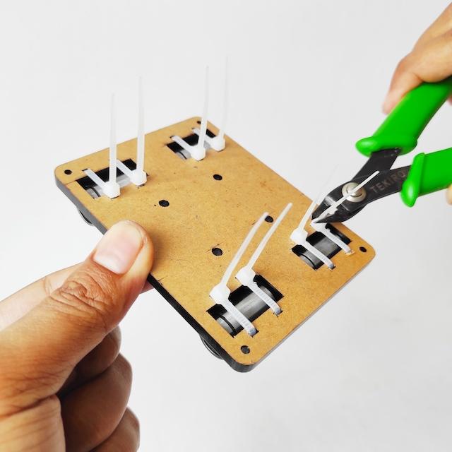
Prepare parts as below:
- Acrylic Parts
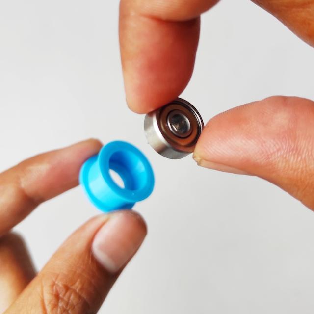
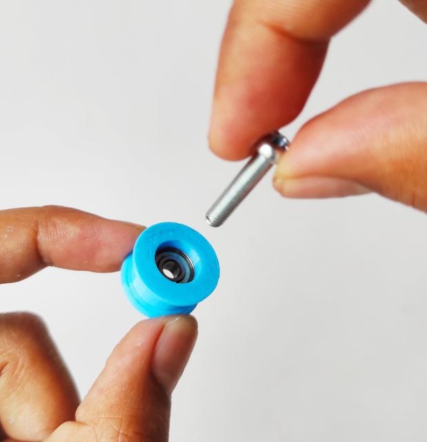
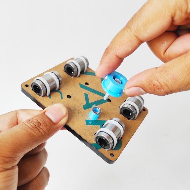
- 4x Idler 3D Printed
- 4x Bushing 3D Printed
- Y Limit Switch + Extended Cable
- 8x Slider Bearing LM8UU
- 4x Bearing 624ZZ
- 4x Screw M4x20mm
- 4x Washer M4
- 4x Spacer M3x25mm
- 4x Screw M3x8mm
- 4x Nut M3
- 8x Washer M3
- 2x Screw M2x12mm
- 2x Nut M2
- 20x Camble Ties 10mm
- Place the 4 LM8UU in the square holes on acrylic part bottom slider holder as shown below.
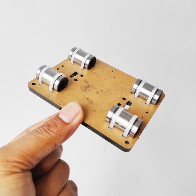
- Then tie the LM8UU body using cable ties.
- Also for the other four LM8UU.
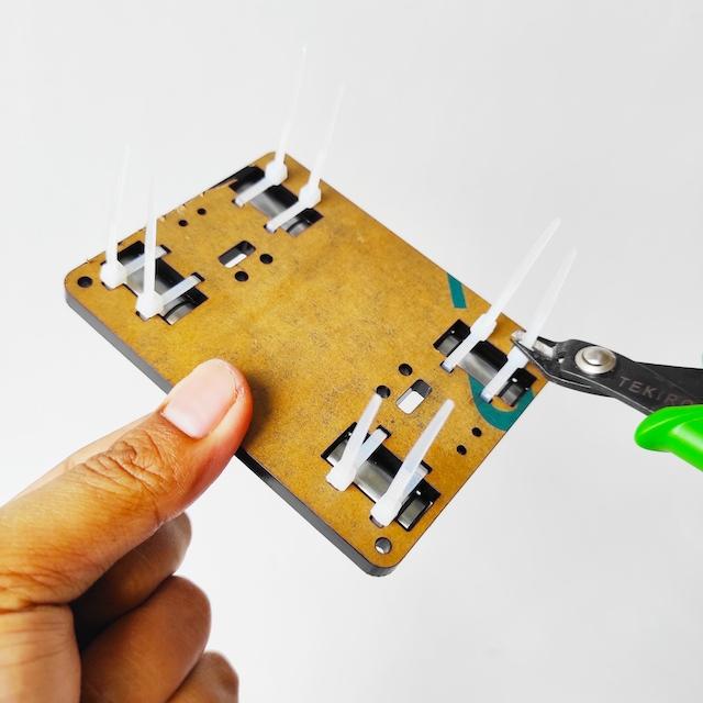
- Cut the remaining length of the cable ties.
- Insert the bearing 624ZZ into the idler hole.
- Insert M4x20mm screw into inner hole of bearing 624ZZ.
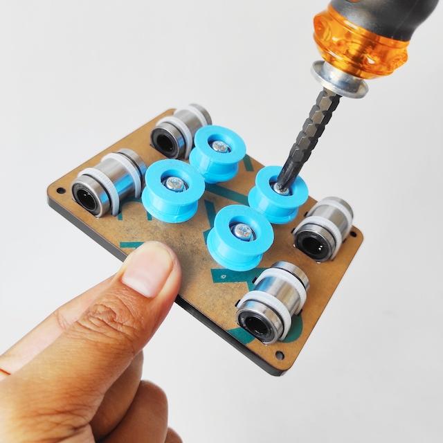
- Stack the 3d printed bushing with the M4 washer, place it in the hole, then install the idler assy on it.
- Also install for other idler assy and tighten.
Top Slider Holder
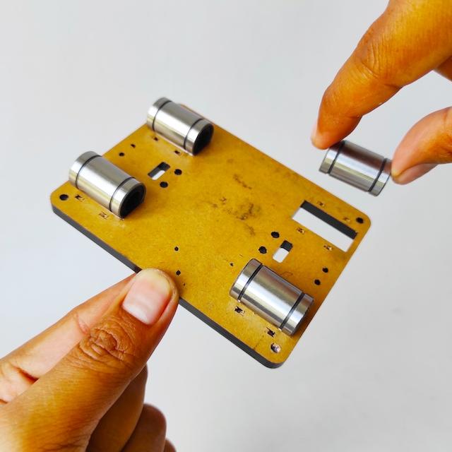




- Place the 4 LM8UU in the square holes on acrylic part top slider holder as shown below.
- Then tie the LM8UU body using cable ties.
- Also for the other four LM8UU.
- Cut the remaining length of the cable ties.
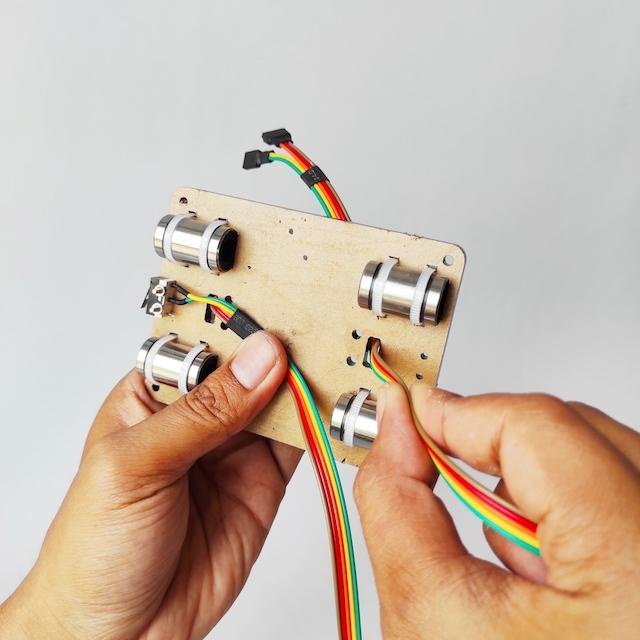
- Install Y limit switch as shown below, then tighten use M2x12mm screw & nut.
- Put and arrange the extended cable as shown below.
- Then tie the cable using cable ties.
- Cut the remaining length of the cable ties.
- Part of Top Slider Holder Assy are ready to be combined.
Slider Holder Assy
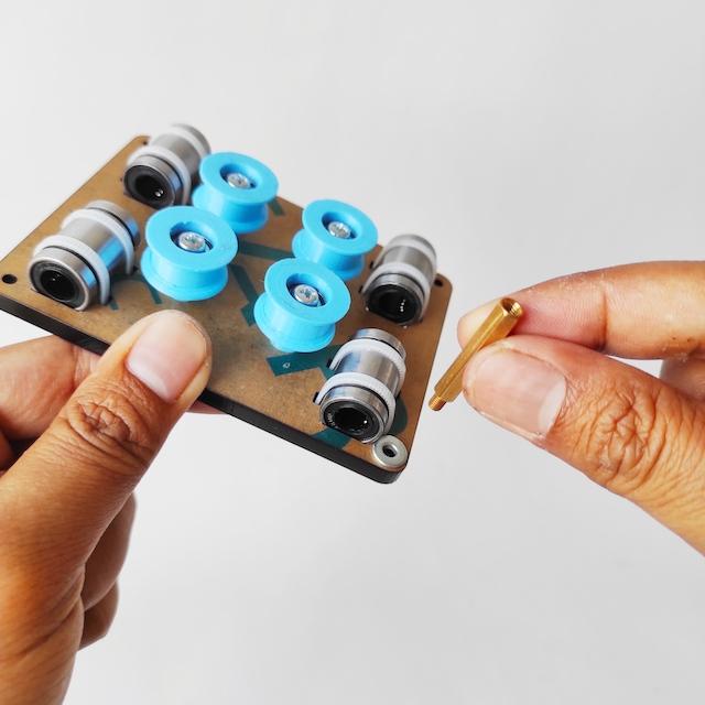


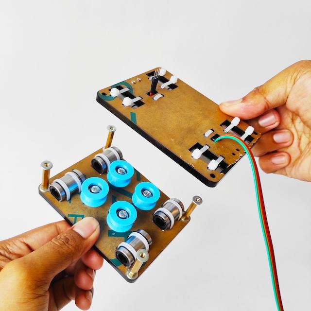

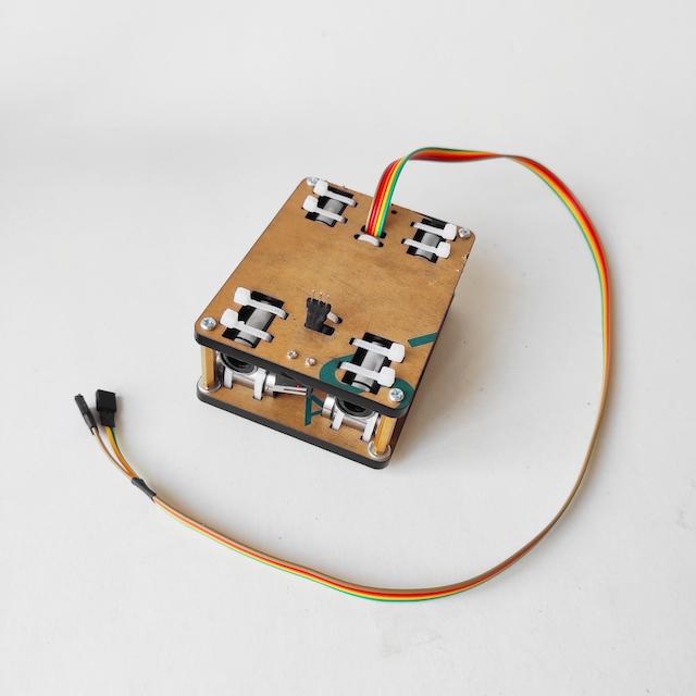
- Attach M3 washer and M3x25mm Spacer into Bottom Slider Holder Assy as shown below.
- Then tighten use hex key.
- Also install for other Spacer M3.
- Install Top and Bottom Slider Holder Assy, attach washer M3 as shoen below.
- Then tighten use 4 M3x8mm screw.
- Finally, the Slider Holder Assy is done.
Threaded Rod
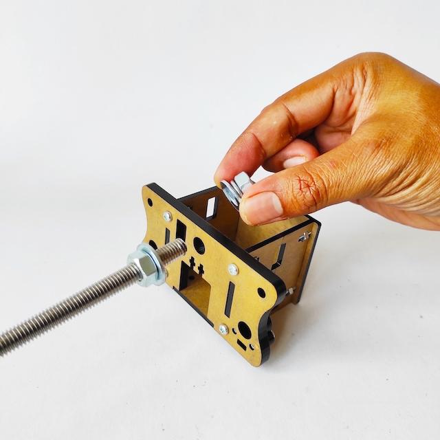
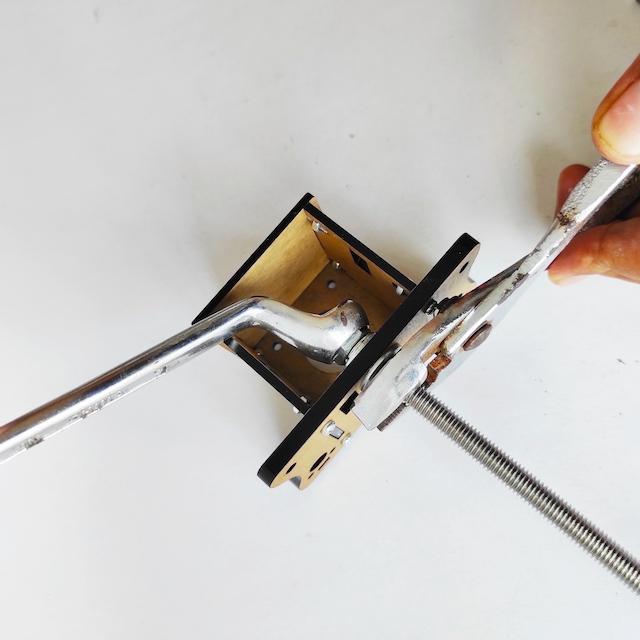
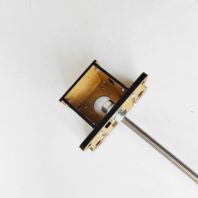
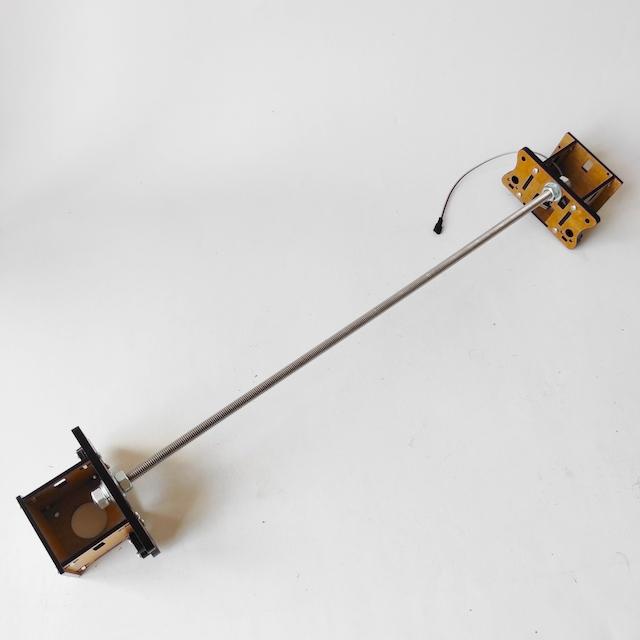
- Install M8 nut and M8 Washer into threaded rod 460mm, then insert onto hole of 5mm base acrylic. then clamp with M8 washer, spring washer & nut
- Tighten M8 nut use hex key.
- Install and tighten on other side treaded rod.
Linear Rod X


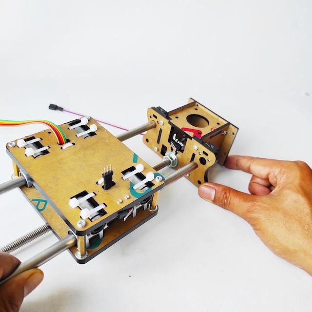
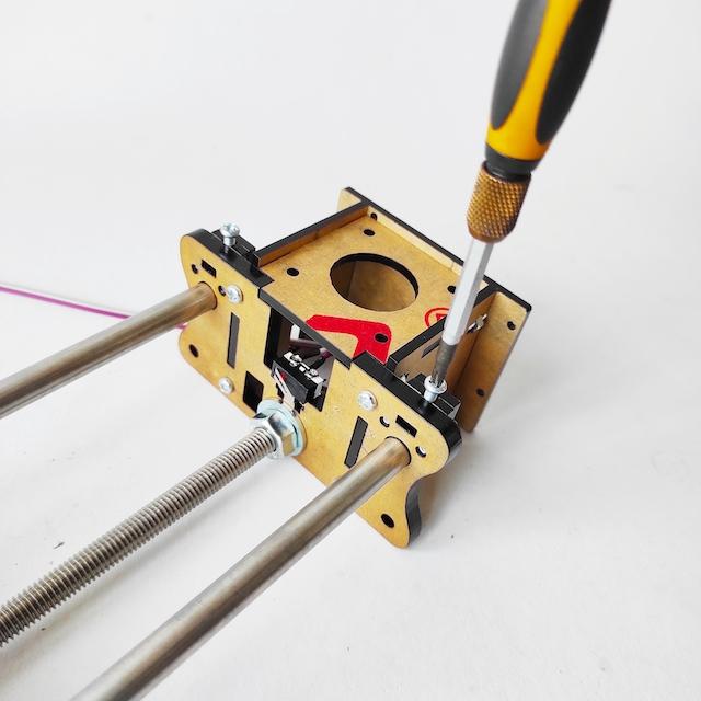

- Insert two 8mm linear rod 450mm from outside (left) Y Motor Holder Assy.
- Continue insert two linear rod into slider bearing LLM8UU of bottom slider holder.
- Insert end of two linear rod into X Motor Holder Assy.
- Tighten use M3x15mm screw as stopper each end of linear rod.
- The X axis slider is done.
Linear Rod Y
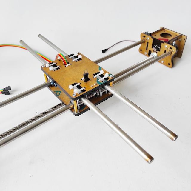

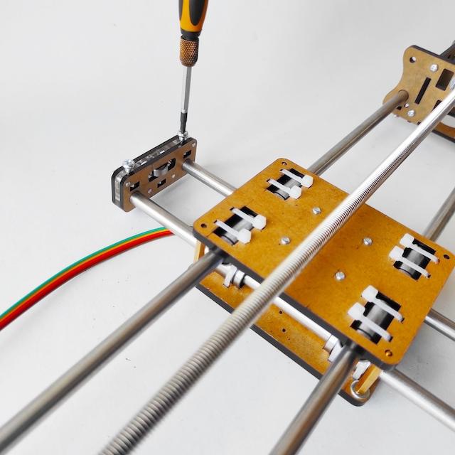
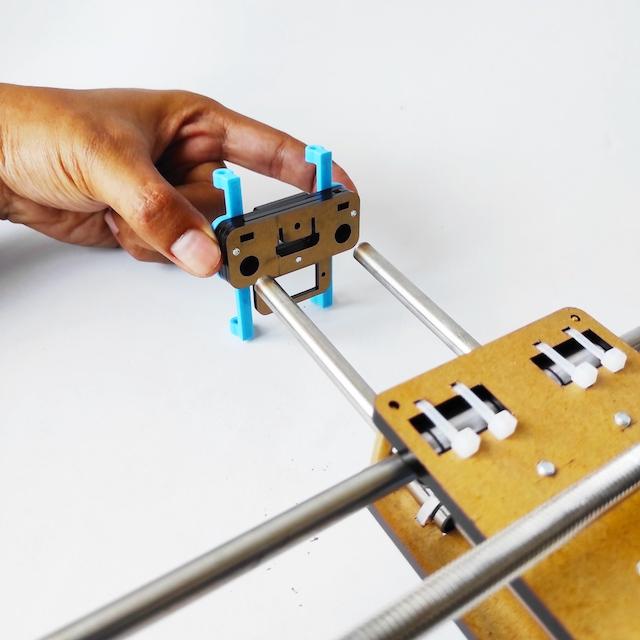

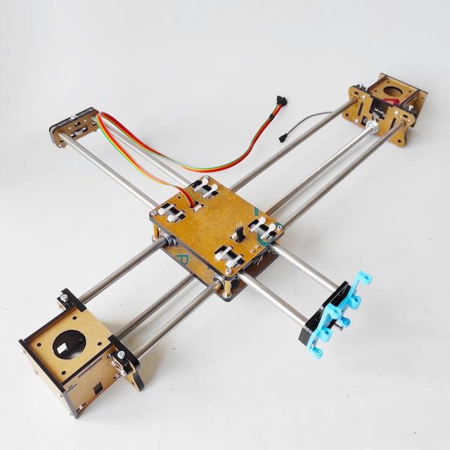
- With the bottom side facing up, insert two 8mm linear rod 350mm into slider bearing LLM8UU of top slider holder.
- Install back support assy into end of back Y linear rod.
- Tighten use M4x15mm screw as stopper end of back Y linear rod.
- Install front support assy into end of front Y linear rod.
- Tighten use M4x15mm screw as stopper end of front Y linear rod.
- The Y axis slider is done.
Install Motor
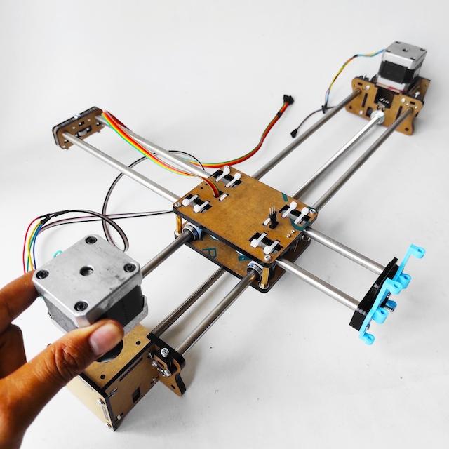

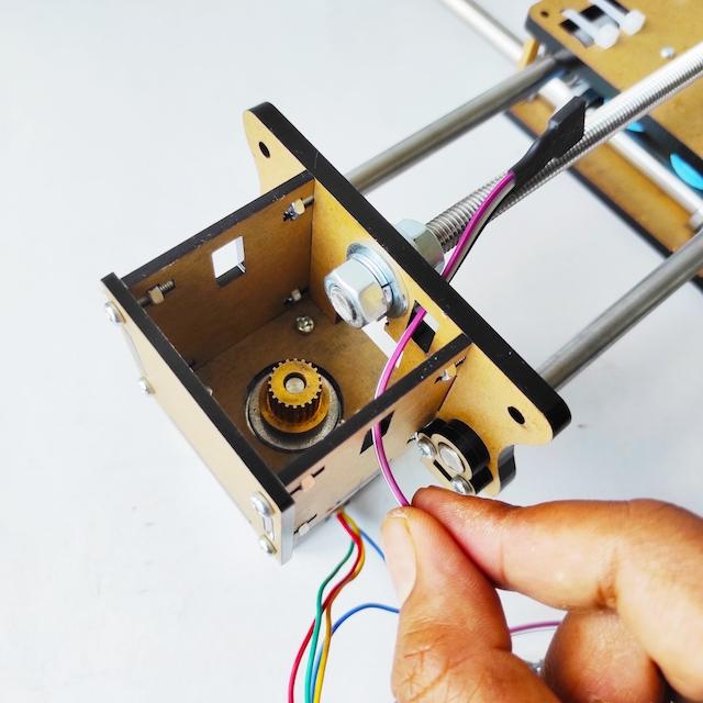


- Install stepper motor Nema17 into Motor Holder. X axis motor on the right side with sort cable, Y axis motor on the left side with extended cable.
- Each stepper motor tighten use 4 M3x6mm.
- Place and arrange extended cable following threaded rod.
- Tie together with threaded rod using cable tie.
Install Belt

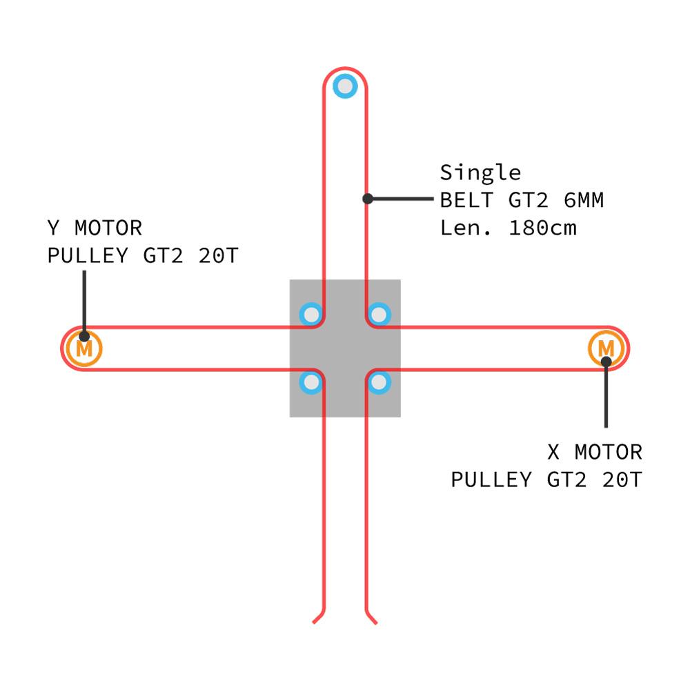
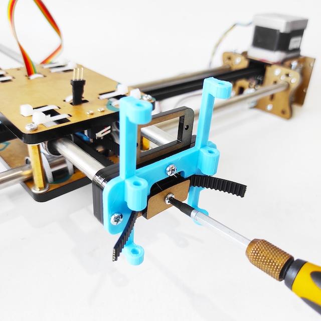

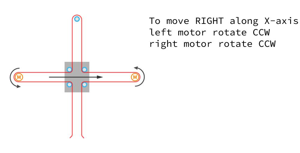


- Now install the belt GT2 180cm though all of the motor pulleys and into inside of slider holder assy. Make sure the belt is properly engaged in all pulleys and idlers. Make sure all parts are fully pushed onto the 6mm shafts.
- Pull the belt tight while engaging the belt in the teeth of the belt grip. Trim the end of the belt with a little 12mm tail exposed. It will be trimmed closer later.
- Because this Drawbot uses a long single belt that is interconnected between motor X and motor Y. The working principle of the movement will be slightly different from usual, to understand you can pay attention to each motor movement.
Install Servo

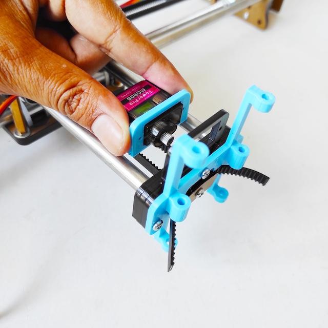

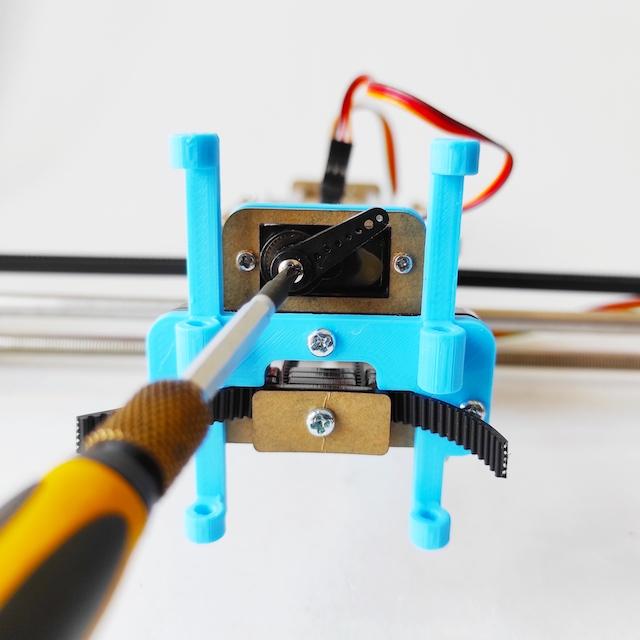
- Attach 3D printed bumper on the micro servo MG90 body.
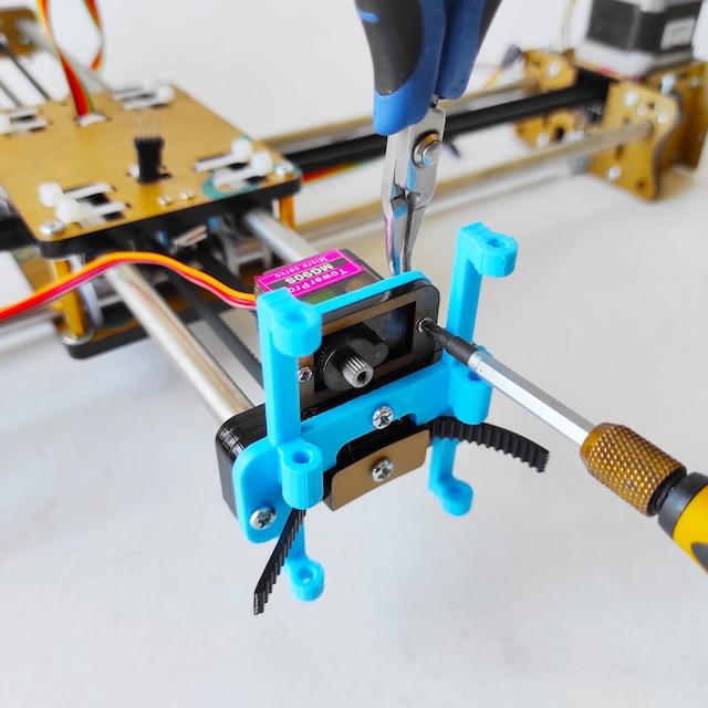
- Install servo into backside of Front Support assy as shown below.
- Tighten use 2 M2x110mm & nut.
- Connect servo pin header to extended cable on the Slider Holder assy.
- Install horn of servo with enough position to lift the pen holder (about 30 degree) when G-code command for servo Z5 or lift pen command.
Install Pen Holder
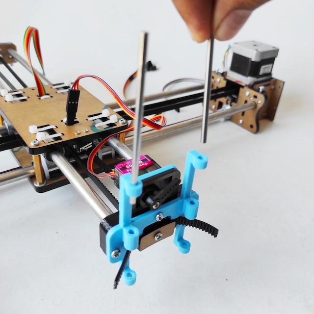


- Insert two 3mm linear rod from top side 3D printed pen holder support.
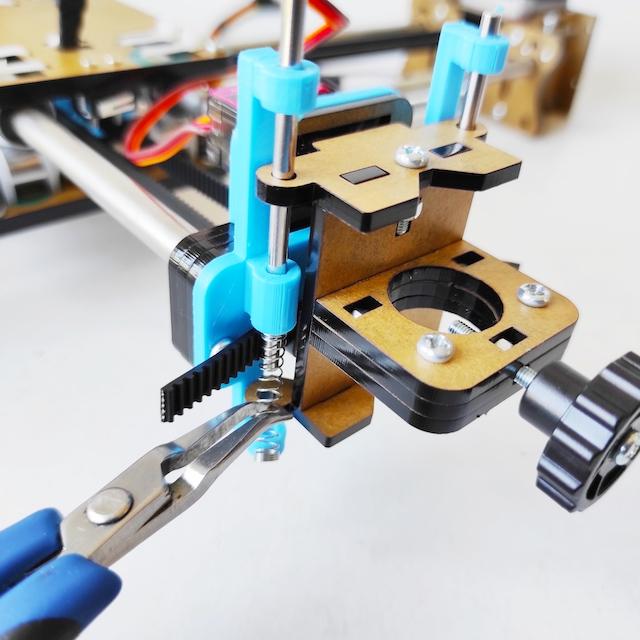
- Then attach pen holder assy, continue insert linear rod on top pen holder assy.
- On the bottom pen holder attach one spring into 3mm linear rod.
- Test manually for lift down and lift up of pen holder.
Install Controller

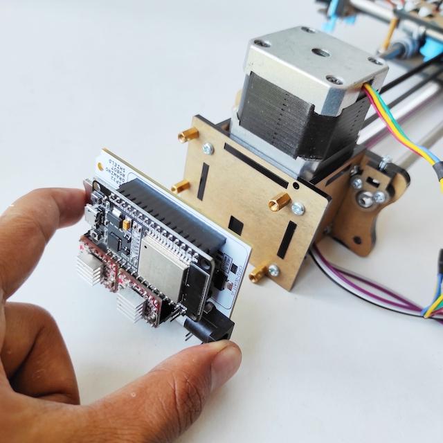
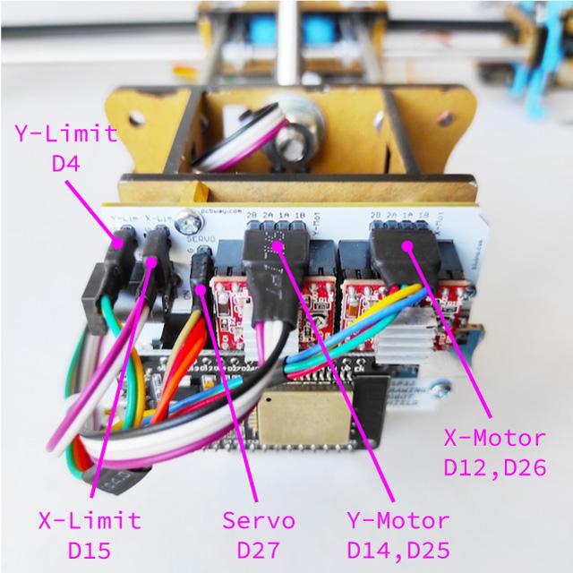

- Install controller (ESP32 Drawing Robot Shield) on the right X Motor Holder assy as shon below. Use spacer M3x8mm.
- Install controller with microSD slot facing to front and power connector facing to back.
- Connect the pin header as shown bellow, pay attention not to get the wrong orientation.
- X and Y Stepper Motor Nema17
- X and Y Limit switch
- Servo MG90
- nsert micro-SD card.
Drawbot Is Ready


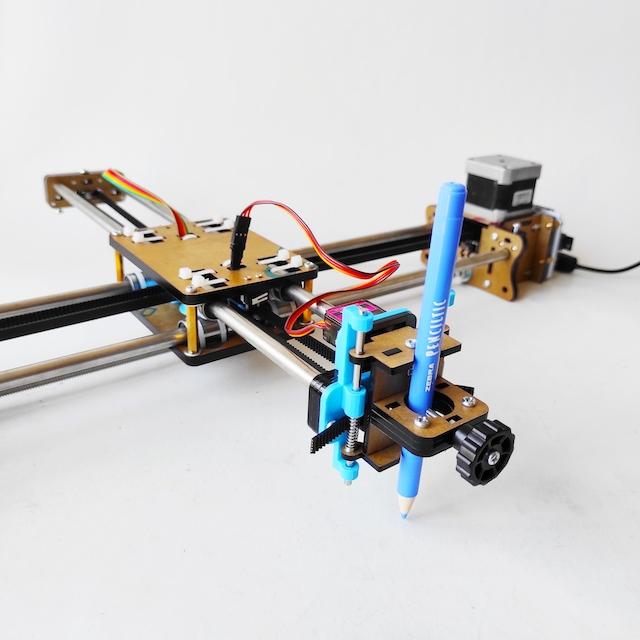
The hardware setup of Drawbot are complete. The next step is to upload and setup firmware.
Compile and Upload Firmware
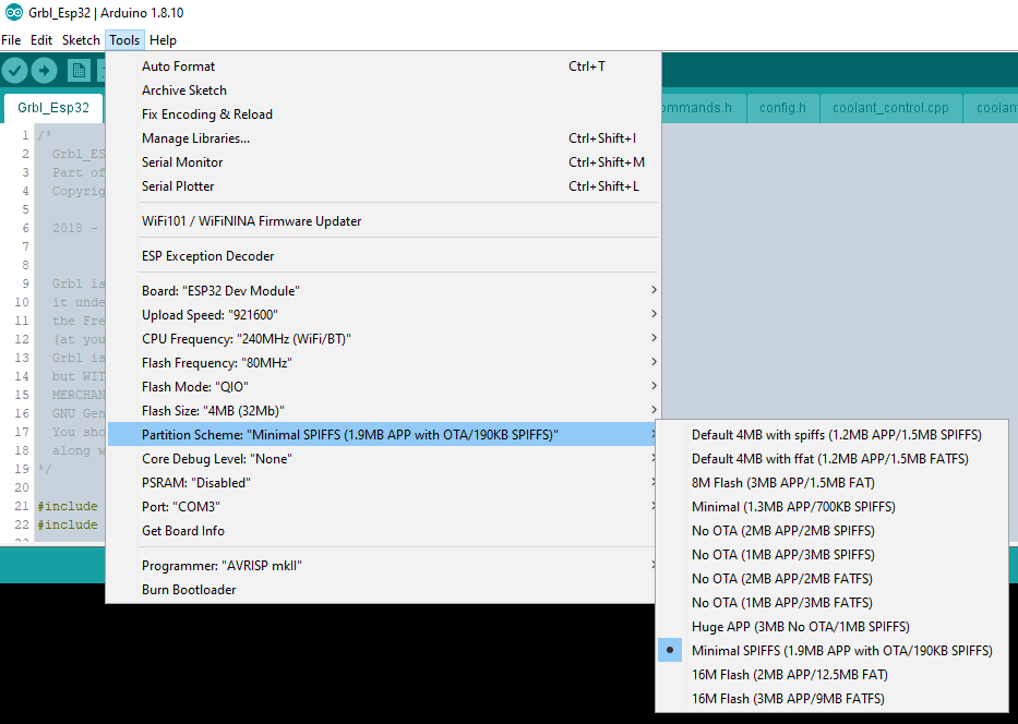


The ESP32 version of the Drawbot uses Grbl_ESP32 firmware.
Follow the compile instructions.
Use the drawbot.h file for your machine definition files.
- Copy eggbot.h file into "../Grbl_Esp32-main/Grbl_Esp32/src/Machines/"
- then on file Machines.h for customize set up to #include "Machines/drawbot.h"
- Select the Minimal SPIFFS (1.9MB APP with OTA/190KB SPIFFS) partition scheme.
- Select the serial port that corresponds to your ESP32.
- Click on the Upload button to begin the compilation/upload process.
- Scroll to the bottom to see the final upload result "Done Uploading".
Software for GRBL


The ESP3D-WEBUI project has been modified for use with Grbl_ESP32 by Luc of luc-github so you can control Grbl_ESP32 over WiFi using any browser, without needing any other programs. Follow guideline here.
LaserGRBL is one of the best Windows software for image Laser Engraving. LaserGRBL is able to load any image, pictures and logo and send to your laser engrave with few click. Follow the instruction for setup LaserGRBL with Drawbot here.
Lightburn is in trial version for one month but wanting to buy it costs very little and gives you the possibility to use it on 2 computers at the same time. Follow the instruction for setup Lightburn with Drawbot here.