Dual SHT41 Temperature & Humidity Monitor With Raspberry Pi Pico | Temp-Hume Display | SHT41 | Sensirion | Raspberry Pi Pico | Industrial Grade Sensor
by akashwave rf in Circuits > Raspberry Pi
894 Views, 5 Favorites, 0 Comments
Dual SHT41 Temperature & Humidity Monitor With Raspberry Pi Pico | Temp-Hume Display | SHT41 | Sensirion | Raspberry Pi Pico | Industrial Grade Sensor
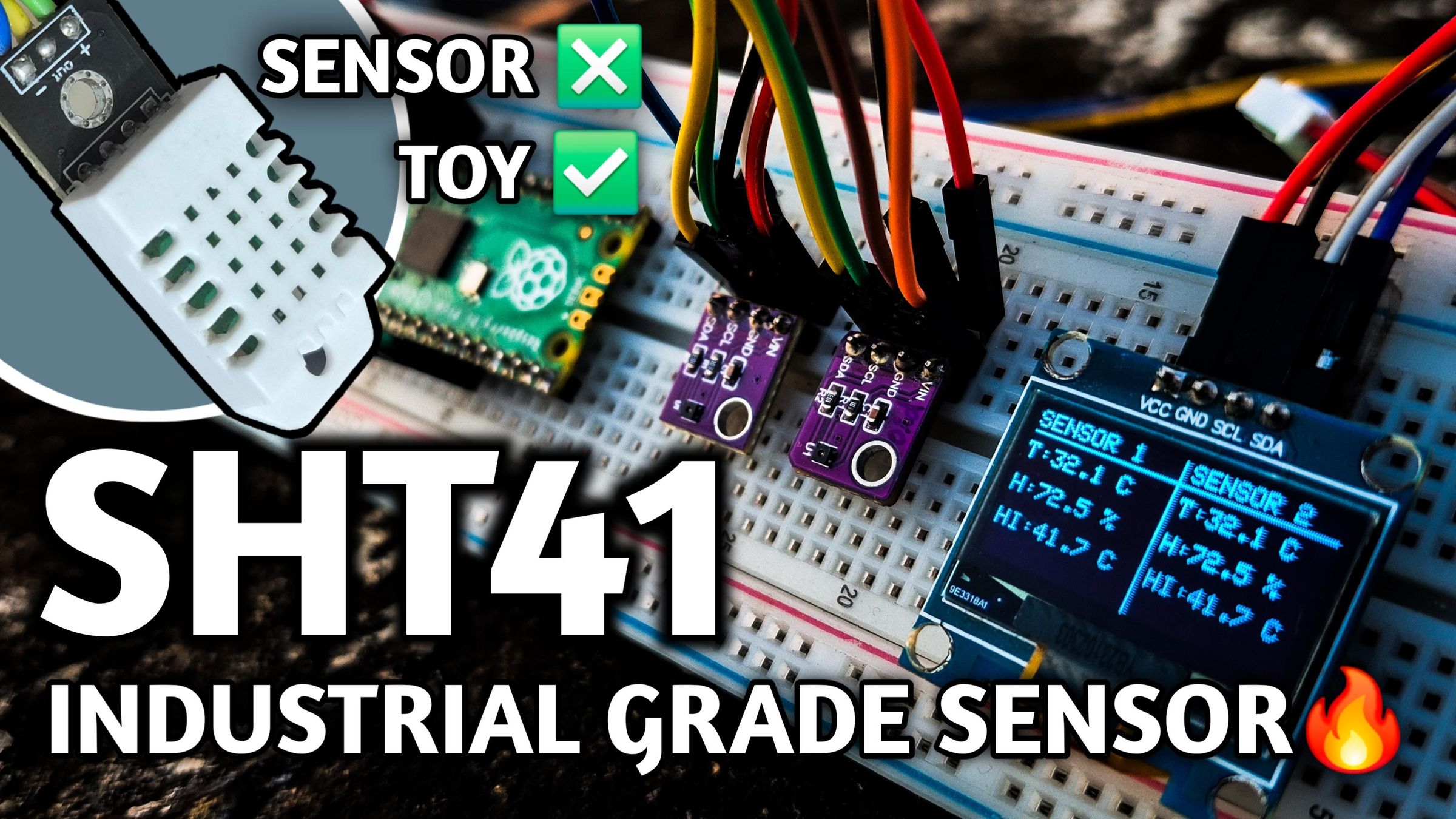
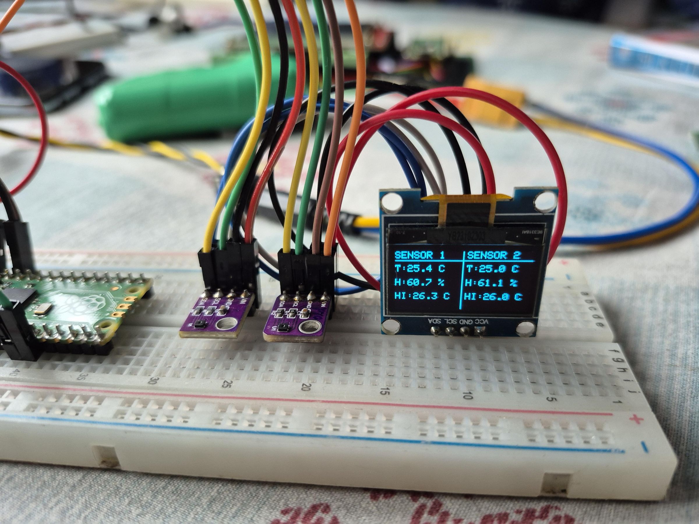

In this tutorial, I’ll show you how to build a dual-sensor temperature, humidity, and heat index monitoring system using two industrial-grade SHT41 temperature and humidity sensors, a Raspberry Pi Pico, and a generic 128×64 I²C OLED display.
I’ll also provide the Arduino code and circuit diagram used in this project.
I also made a detailed YouTube video documenting the entire experiment, including a practical comparison between the SHT41 and DHT22. I shared my real-world experience and demonstrated the difference between a basic “toy” sensor and an industrial-grade sensor.
If you're interested, you can watch the full video here- https://youtu.be/gvT-3zCykAo
Supplies
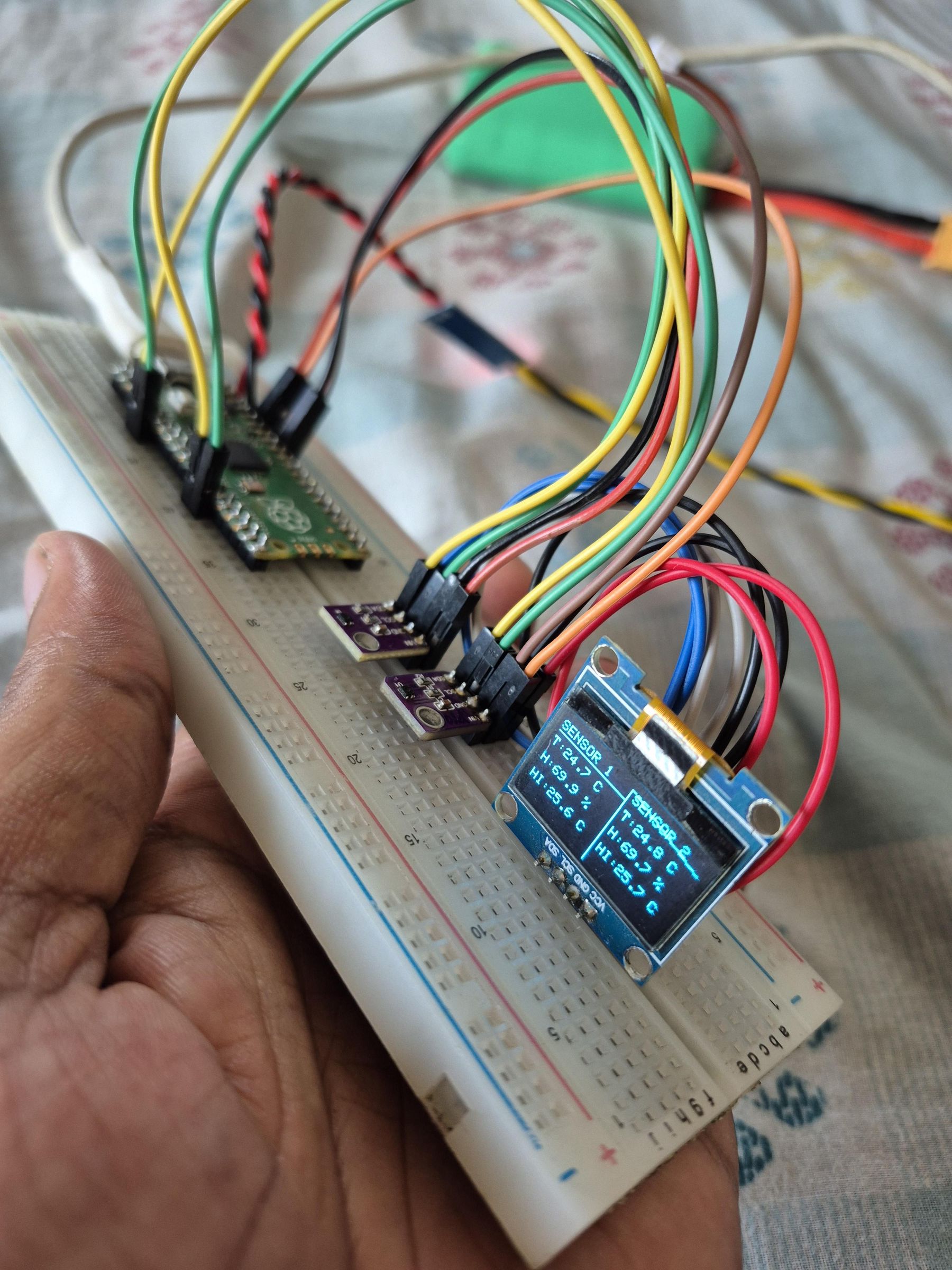
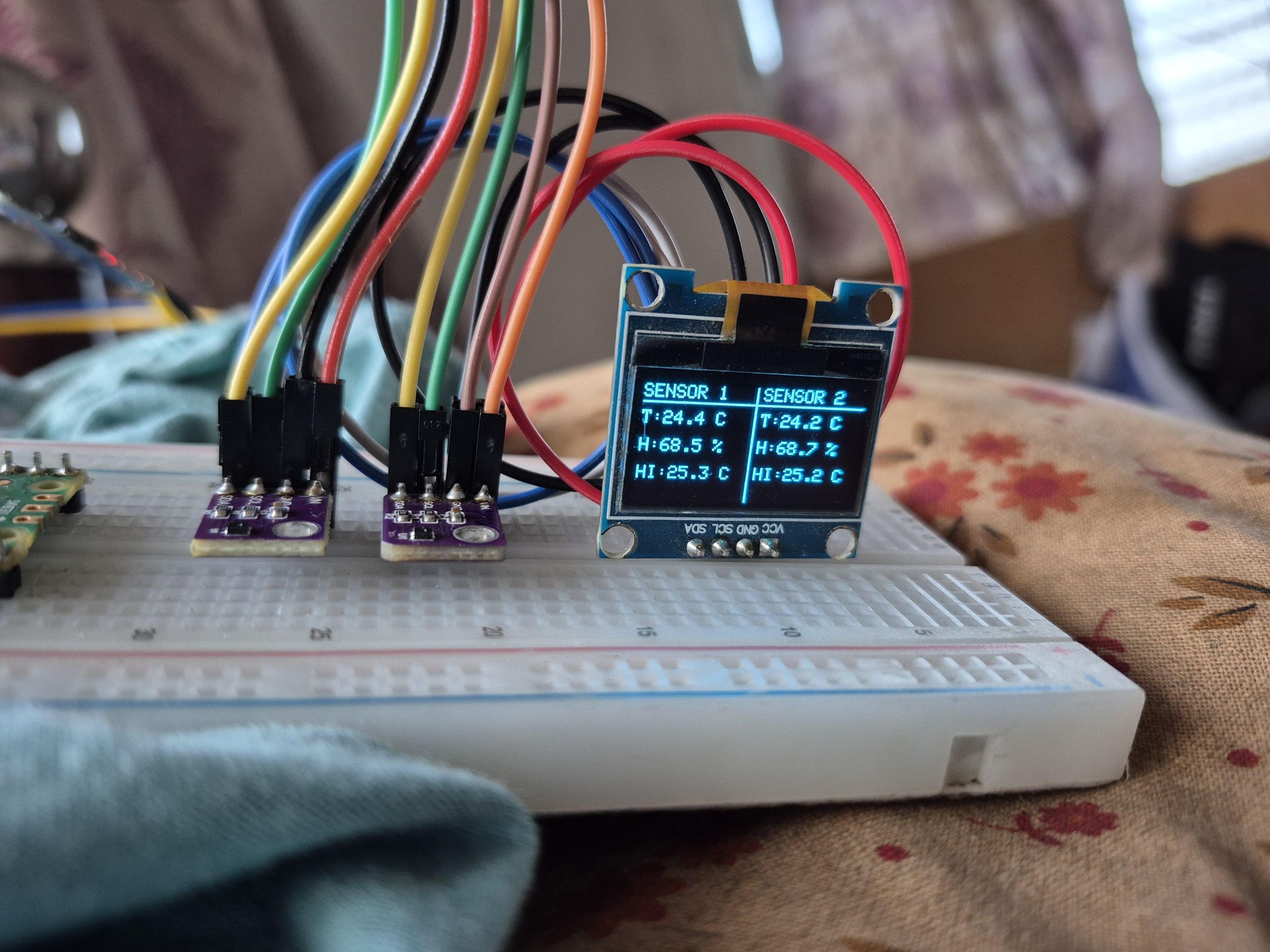
- SHT41 one or two
- Raspberry Pi Pico
- Male to Male Jumper Cable
- 128*64 OLED Display
- Breadboard
- USB Cable
SHT41 Vs. DHT22
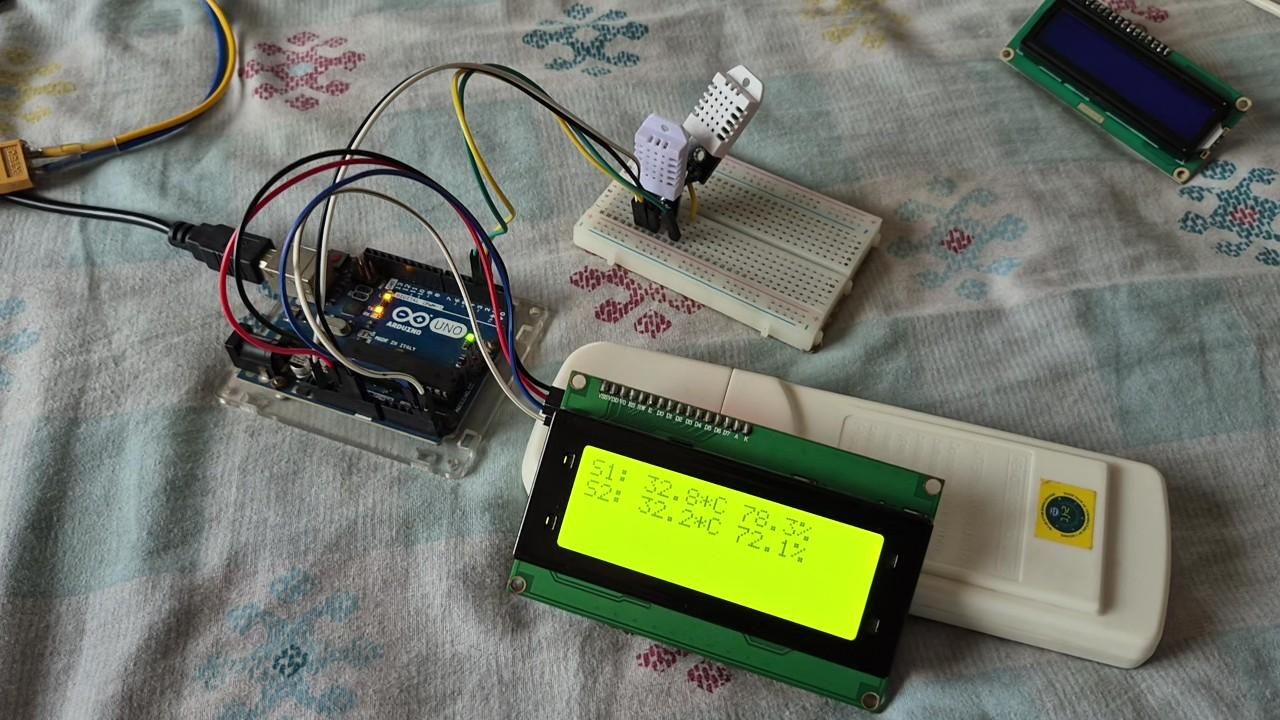
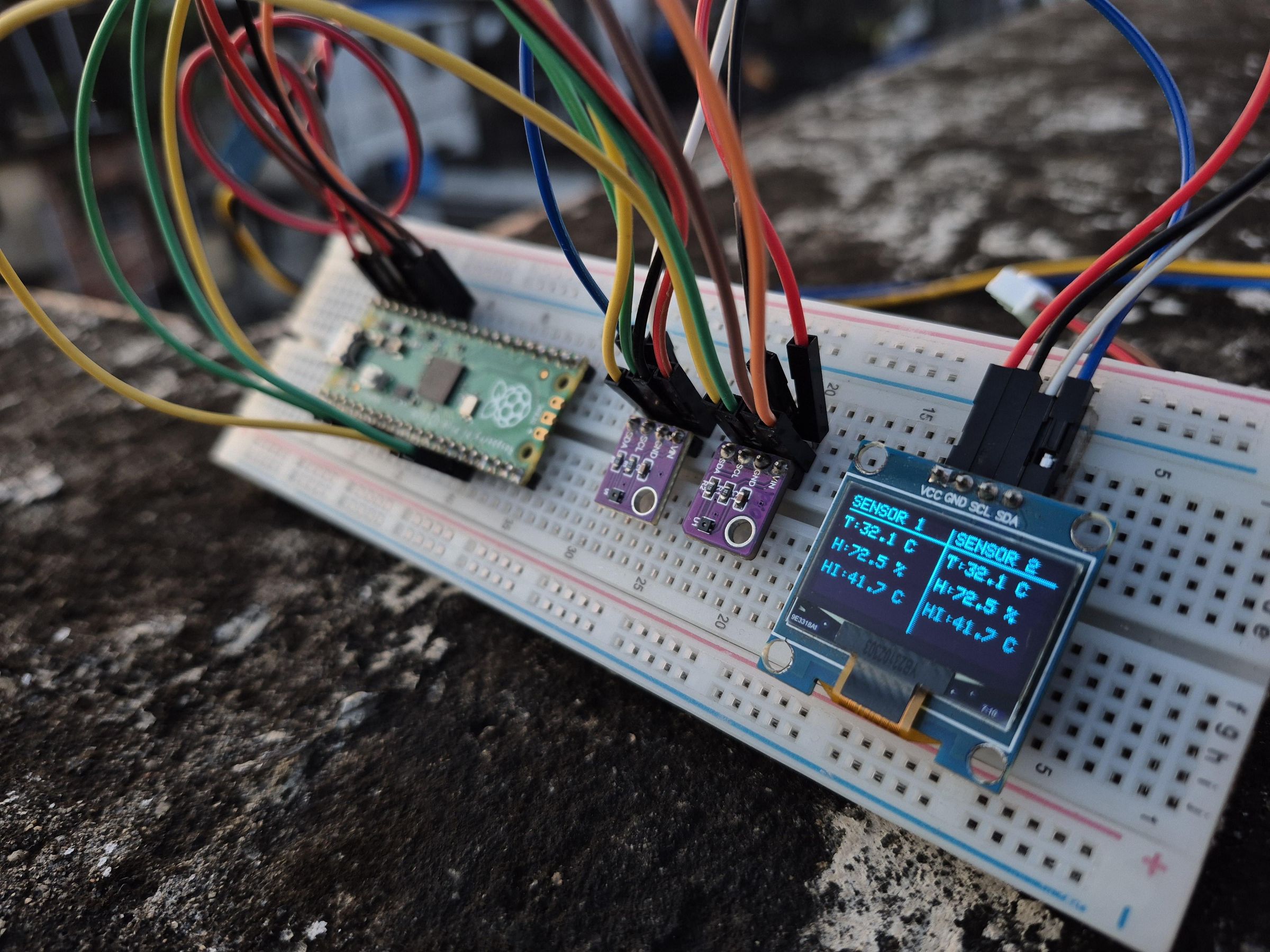
I have also made a detailed video comparing the SHT41 with the very popular and inexpensive DHT22 sensor.
In that test, I used two DHT22 sensors and two SHT41 sensors at the same time. The data from the two DHT22 sensors showed noticeable differences, while the factory-calibrated SHT41 sensors produced very similar readings — and sometimes exactly the same readings.
If you’re interested, I’ve included the YouTube video link here- https://youtu.be/gvT-3zCykAo
I hope you enjoy the comparison!
Circuit Diagram
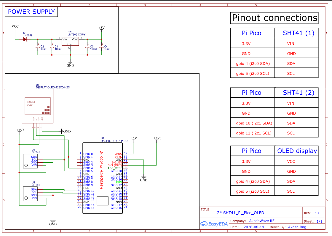
As you can see in the schematic, I have used two SHT41 sensors.
However, you can also use this project with only one SHT41 sensor. If one sensor is not connected, the display will simply show "Sensor Not Found" for that sensor, while the connected sensor will continue to display its readings normally.
Why Raspberry Pi Pico?
The SHT41 does not have a pin for changing its I²C address. Since both sensors use the same I²C address, connecting them to the same I²C bus would cause an address conflict.
The Raspberry Pi Pico solves this problem because it has two separate I²C interfaces: I²C0 and I²C1. Therefore, we can connect one SHT41 sensor to each I²C bus and use both sensors independently.
I had also explained this circuit diagram completely in details on my YouTube video on this topic, if you are interest, click here to watch it- https://youtu.be/gvT-3zCykAo
Downloads
Arduino Code
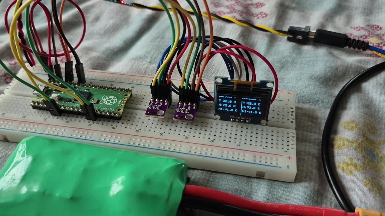
You can simply copy and paste the provided Arduino code and upload it to your Raspberry Pi Pico.
One small thing to note: in my project, I mounted the OLED display upside down on the breadboard. Therefore, I used the following function to rotate the display:
display.setRotation(2);
If your OLED is mounted in the standard orientation, simply remove or comment out this line. This code also has been explained in the YouTube Video, CLICK here to checkout it.
Thank You
I hope you find this project useful! If you do, please consider liking the project and sharing it. Also don't forget to checkout my full length YouTube video on this topic on my YouTube channel AkashWave RF, and subscribe the channel to stay tuned with me. you can click here to watch the video https://youtu.be/gvT-3zCykAo . Stay tuned with me, and after my exam, a lots of interesting videos on RC HOBBY, RF and LoRa based videos are on the way. Thank you!