Dual Text Modern Concept Lamp
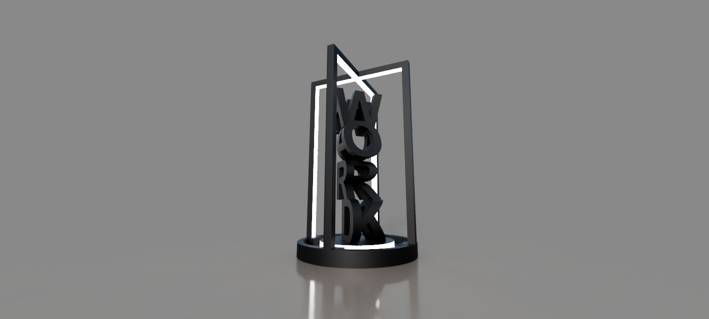


Have you ever seen a dual-text illusion and wondered how they managed to make it? In this Instructable, you will learn how to make your very own with Fusion 360. To make things more interesting, I made it into a modern lamp design that you could potentially 3D print and add some LED strips to make it an actual lamp (unfortunately I don't have a 3D printer).
Supplies

- Some creativity
- Fusion 360
Brainstorm
First, we need to come up with some ideas for the dual-text illusion. For mine, I decided to make it motivational-themed so I decided to go forth with "Work Hard". Ideally, you want two words with the same number of letters to ensure they align perfectly for the best results. However, you could fill in a letter space with the symbol or icon to add a touch of creativity.
Here are some examples that I was considering just for some inspiration:
- [🌟Shine] [Bright]
- [Rise] [High]
- [Dream] [🌙Big☁️]
- [Live] [Love]
Modeling the First Word
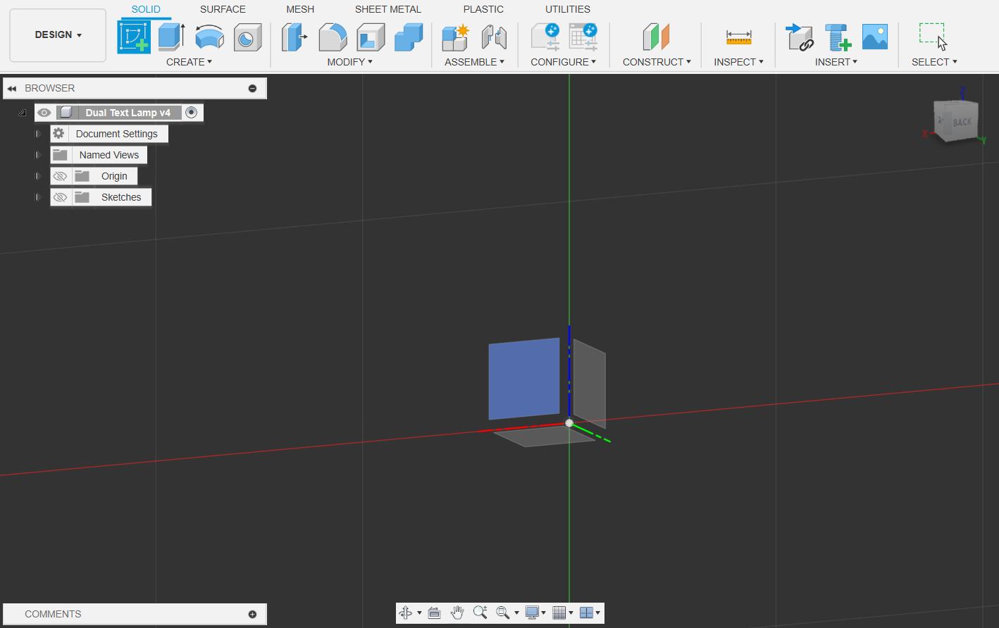
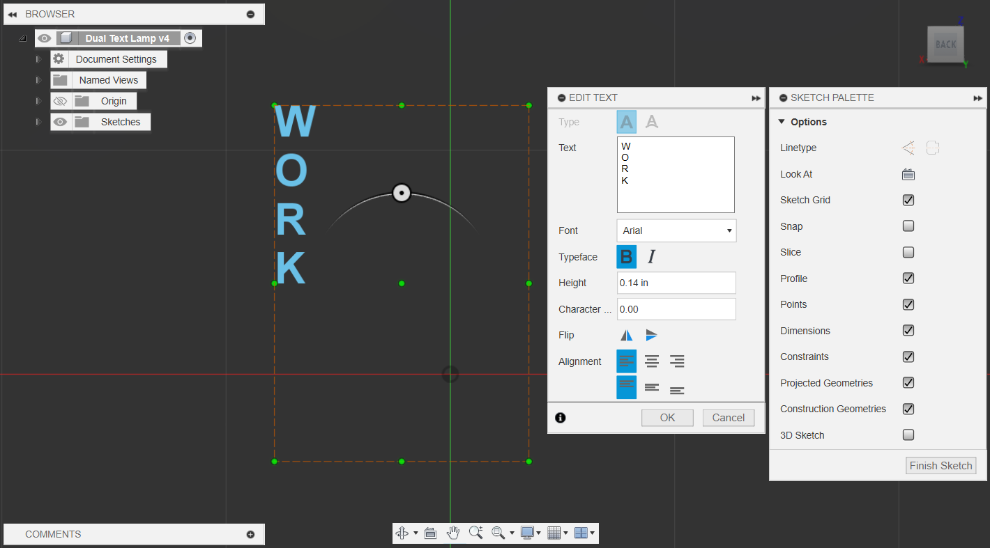

It's time to open up Fusion360! Now that we have our words in mind, we want to create a sketch and then use the 'text' tool found in the CREATE drop box and type out our first word.
Take note of the font size ('Height') and make sure that it's the same for the next word as well. Feel free to use whatever font, but to keep things simple, I went with the default Arial. Also, make sure to hit 'Enter' after each character to space them out vertically.
Finally, click 'finish sketch' and use the 'Extrude' tool (or just press E) and select the sketch to extrude the letters out by a few increments to make them 3D. You don't need to worry about sizing that much, the best feature of Fusion is the history slide at the bottom so you can always go back and adjust the sizing.
Adding the Second Word
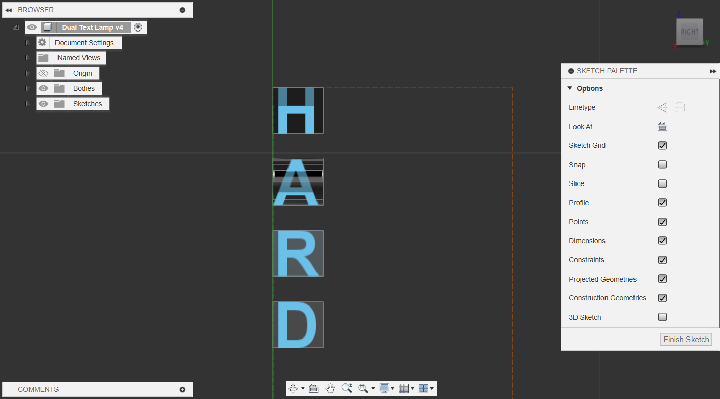
From here, we want to create another sketch on the plane perpendicular to the one we used for the first word. For mine, I created a sketch on the flat face of the 'R' so it is easier to align the letters, but it doesn't matter as long as you make sure the sketch is made perpendicular to the first one.
Now, use the 'text' tool again and add the second word. Again, make sure to separate the letters vertically to align them. Also, try to use the same font size for consistency. You may need to go back and make sure that you extruded the first word enough that the second word is fully inscribed.
Fusing the Letters Into One

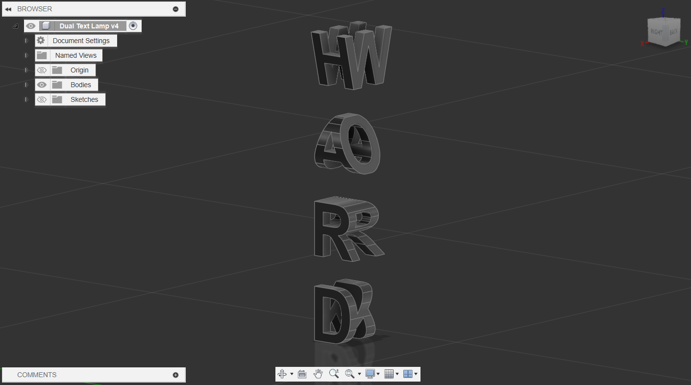
Here is the fun part. Select the sketch that you just made and extrude them outwards. Make sure that they fully extend over the first word, to do this, you may need to change the direction from 'One Side' to 'Two Sides’. Finally, the key step is to change the operation at the bottom to 'Intersect'. This is what allows us to merge the letters to make that dual-word illusion.
The finished result should look like the second visual. As you can see, when we orbit around the object, it now displays different words when viewed from different angles.
Stacking the Letters


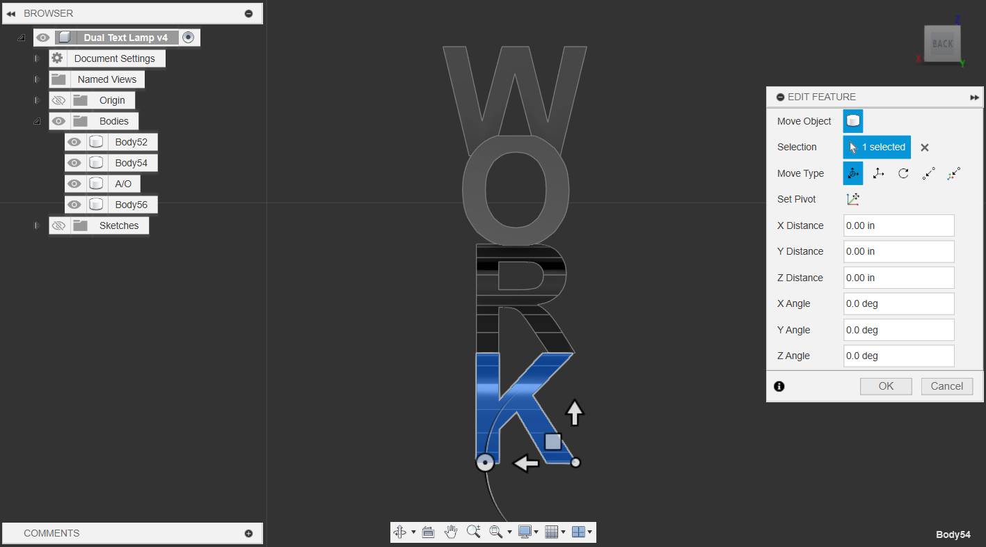
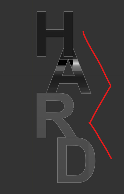
To design the lamp, we need to make sure that the letters aren't just floating in mid-air. To move the letters, select the body and use the 'Move/Copy tool (press M) to stack the letters on top of each other. You also need to make sure that there are some points of contact between the letters (as you can see, I made sure the top of my A/O was under the leg of the H/W).
Tip: Click on one of the faces of the cube in the top right corner (Viewcube) to work in a straight orientation. When you move your letters, it ensures that you are only moving them on a horizontal or vertical plane.
This is the part where you can play around with the design and orientation to make it unique. For mine, I kind of embed the W with the O to make things work for me. Also, I went with a zig-zag orientation for 'HARD' to make it more interesting.
Combine the Letters

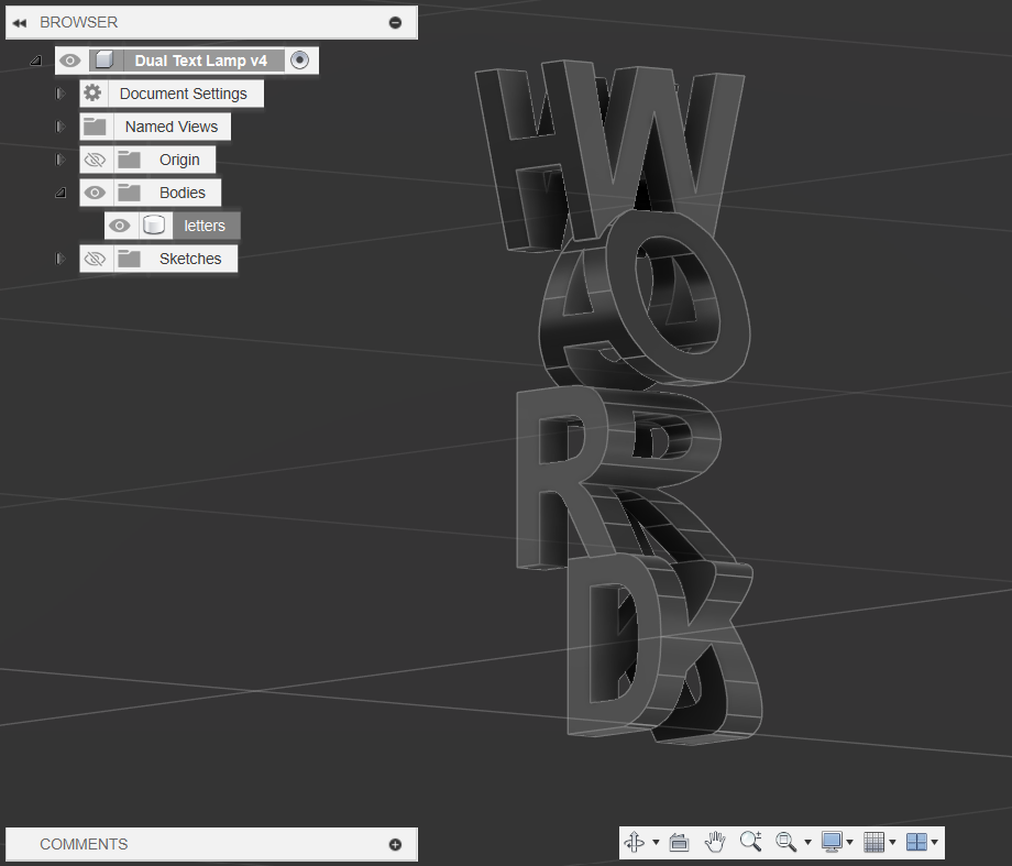
There may be some intersections of the letters, so to get rid of them, select all the letters from the Bodies folder and use the 'Combine' tool found in the 'MODIFY' section. Make sure the operation is set to 'Join' so that it combines all the letters into a single body.
Creating the Lamp Base

For the lamp base, I made a simple circular disk by creating a sketch on a horizontal plane. Then, use the 'Center Diameter Circle' tool to create a circle. Finally, extrude it to add some depth.
Lamp Arc (preliminary Sketchs)


To create a more modern feel, I used a rectangular arc structure/beam. To model this, go back to the sketch that you used to extrude the circular base. Use the 'Offset' tool or the circle tool to create two more inner circles. The smallest circle will determine the thickness of the truss, and the circle between it and the outer edge is going to be our reference line.
Next, draw a center through the circle and an additional parallel line next to it. Then, using the 'Mirror' tool, select the line parallel to the center line as the 'Object and select the 'Mirror Line' as the center line. This should create another parallel line on the other side of the center line.
Now, this should splice up your sketch so that you have 2 square-ish faces on either side as shown in the third picture above. This is what we are going to use to bring out the square-arc structure.
Lamp Arc


From here, we want to use a tool called 'Sweep' which is like extruding a face on a certain path. This is how we can achieve the rectangular arc. To do this, we first need to make another sketch aligned with the centerline that we drew in the last step. Then, use the project tool by pressing 'P' and selecting the reference (middle) circle so that we can reference it in our new sketch. Then, use the intersection point and draw a rectangle with the line tool as shown. You can add a dimension to the height to easily adjust it.
Finally, click 'Finish Sketch' and use the 'Sweep' tool to extrude the beam. Select those squares from Step 8 as the 'Profile' and select the rectangle sketch we just made as the 'Path'. Also, make sure that the 'Operation' is set to 'New Body'.
Adding the Second Arc


To make the other truss, we can use the 'Circular Pattern' tool found under CREATE -> Pattern -> Circular Pattern. Select the beam as the 'Object' and select one of the circles as the 'Axis'. I decided to only make 2 arcs but you could add more if you wish.
Finally, we can combine the two arcs with the base with the 'Combine' tool and choose 'Join' as the 'Operation'.
Base for the Dual Text


To make the dual text pop out more, I made a smaller circular platform on the lamp base. To do this create a sketch on the top face of the lamp base. Then, use the 'Offset' tool to make an inner outline and the 'Center Diameter Circle' tool to draw a smaller base for the dual text.
Now, use the section outlined from the lines made by the offset and the inner circle as the face to extrude. When extruding, we want to extrude downwards by a few increments. Ensure that the 'Operation' is set to 'Cut' and it doesn't completely cut through the base. This creates a slight variation in depth that makes the design of the base more interesting.
Adding the Dual Text

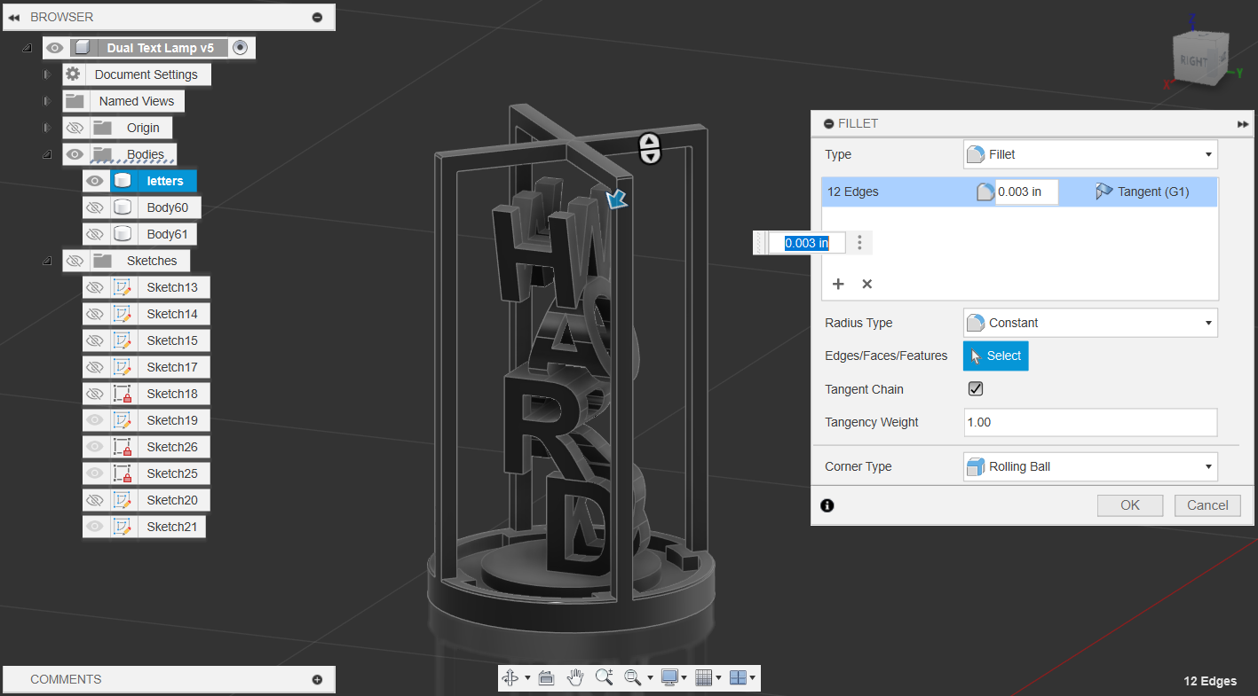
To bring in the dual text, either move it or the stand with the 'Move/Copy' tool. I made sure to rotate the lamp base so that the beams aren't covering up the letters when viewed straight on. Finally, use the 'Combine' tool to join the two together.
For some finishing touches, you can use the 'Fillet' tool by pressing 'F' to round off some edges. For myself, I want to keep the sharper look so I only rounded the base and the corners of the arc a tiny bit.
(Optional) Adding Textures


You could also try to add some texture to your lamp by heading to MODIFY -> Appearance, or just simply pressing 'A'. From here, you can play with many pre-made textures from the Fusion Libray to decorate your lamp. For me, I used a Polished Stainless Steel texture with a darker tint. To apply an appearance, simply drag it onto the parts of the lamp you want to be textured.
To add the lights, I used a LED - 20lm (white) texture found under 'Miscellaneous' -> 'Emissive'. Make sure that when you apply the texture, the 'Apply To' selection in 'Appearance' is set to 'Faces'. This is because we only want to add the LED on certain faces, not the entire lamp.
Finally, to see the textures better, you can head over to Render Mode by clicking the 'DESIGN' at the top left corner and changing it to 'RENDER'. Note that this may require a better graphics card and CPU to run smoothly. To render, click 'Render' at the top and select the settings that best work for you.
And with that, we are finished! I hope you guys enjoyed my first Instructable :)