Dust Covers for FoxAlien Vasto
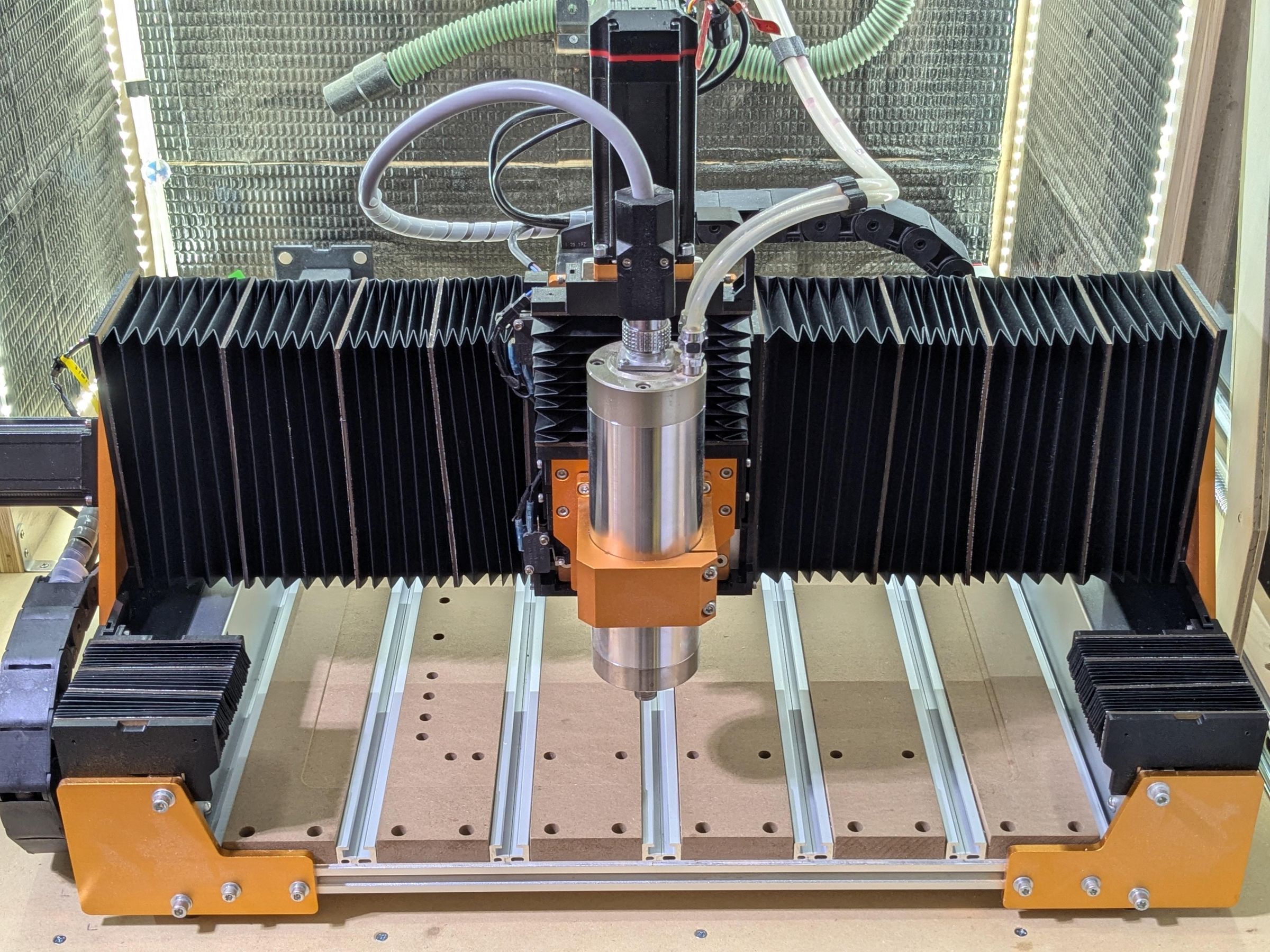
Note: This Instructable is a repost of the article https://cnc.ibeltchev.com/docs/articles/dust_covers/
Dust and chips are a natural part of CNC life. They tend to cling to all surfaces and make a mess.
Unlike professional machines, hobby-level CNC routers lack covers to protect the vital moving parts.
Good dust collection definitely helps. But while I have a vacuum with a dust shoe, I rarely use it. It is noisy, the bristles obscure the cut, and can damage the more delicate surfaces as they drag along. Instead, I use a coaxial fan to blow away the chips and I vacuum them later. This unfortunately contributes to the mess. So I started looking into making dust covers for the X, Y and Z axes.
This article describes the design and the manufacturing process for making the covers.
The profiles
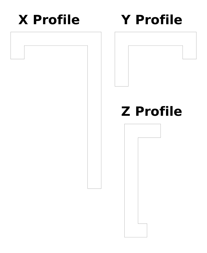
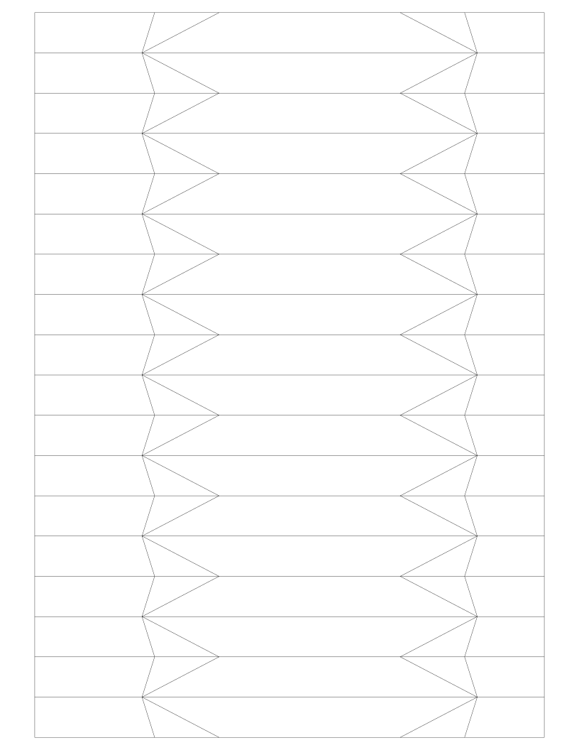
First I came up with optimal profiles for the X, Y and Z rails. They cover as much as possible while staying away from the limit switches and other hardware. See dust_cover_ribs.svg.
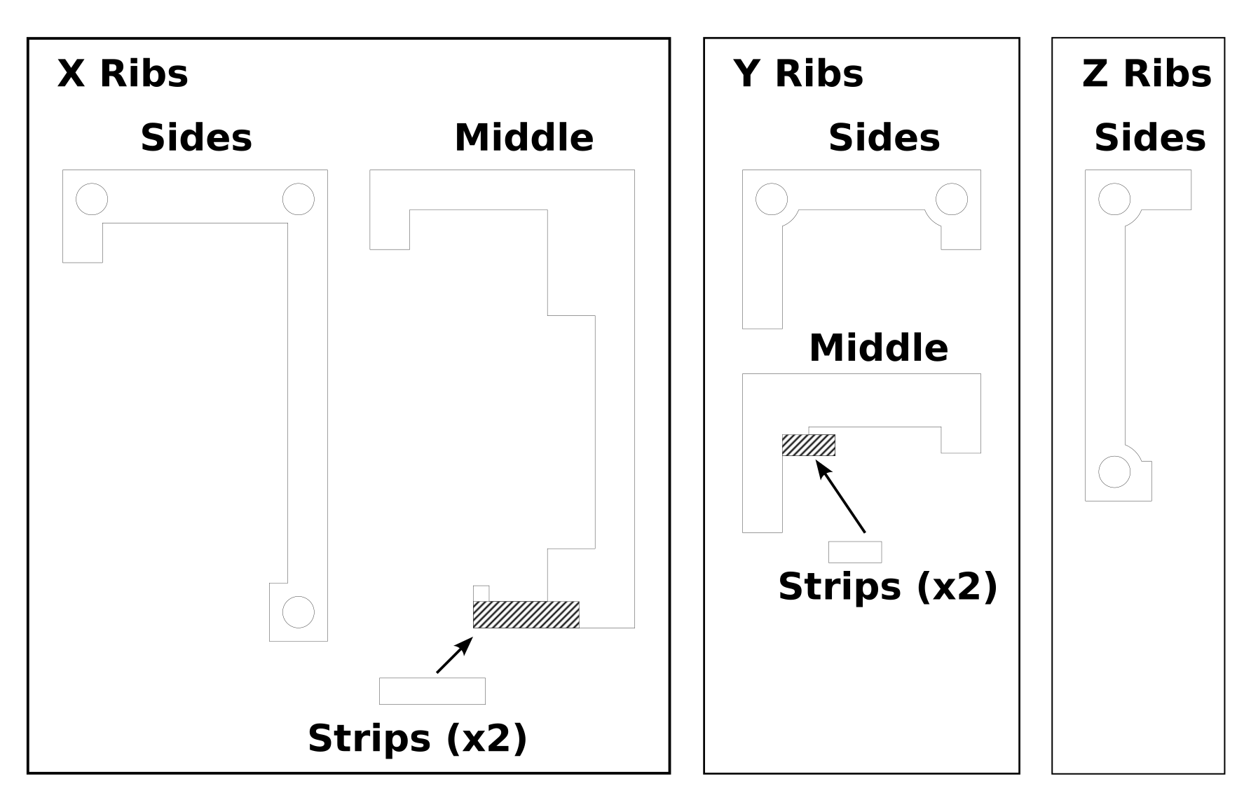
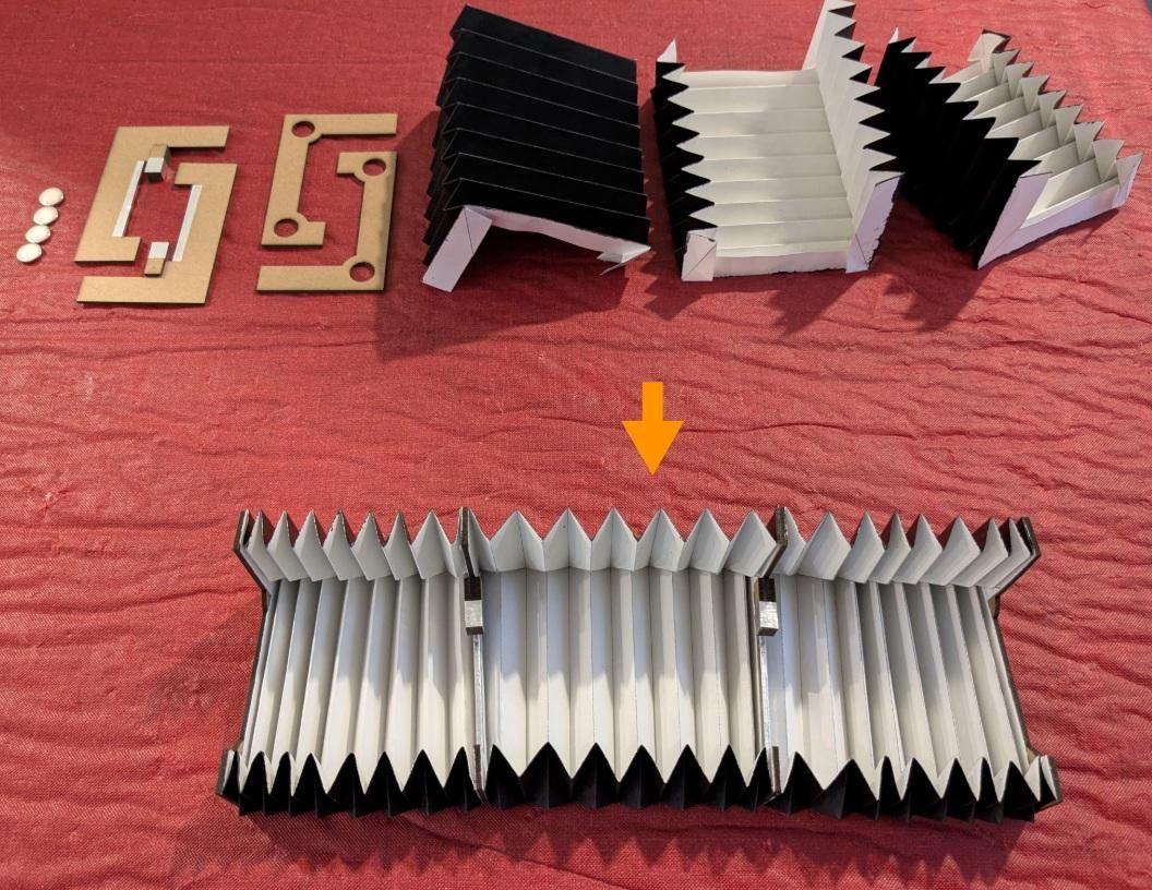
The bellows are assembled from one or more segments, attached together. The segments are separated with ribs. The ribs in the middle have a particular shape to hook onto the frame and glide along the rails. The ribs on both ends have magnets for attaching to the frame. See dust_cover_profiles.svg.
M-fold vs V-fold
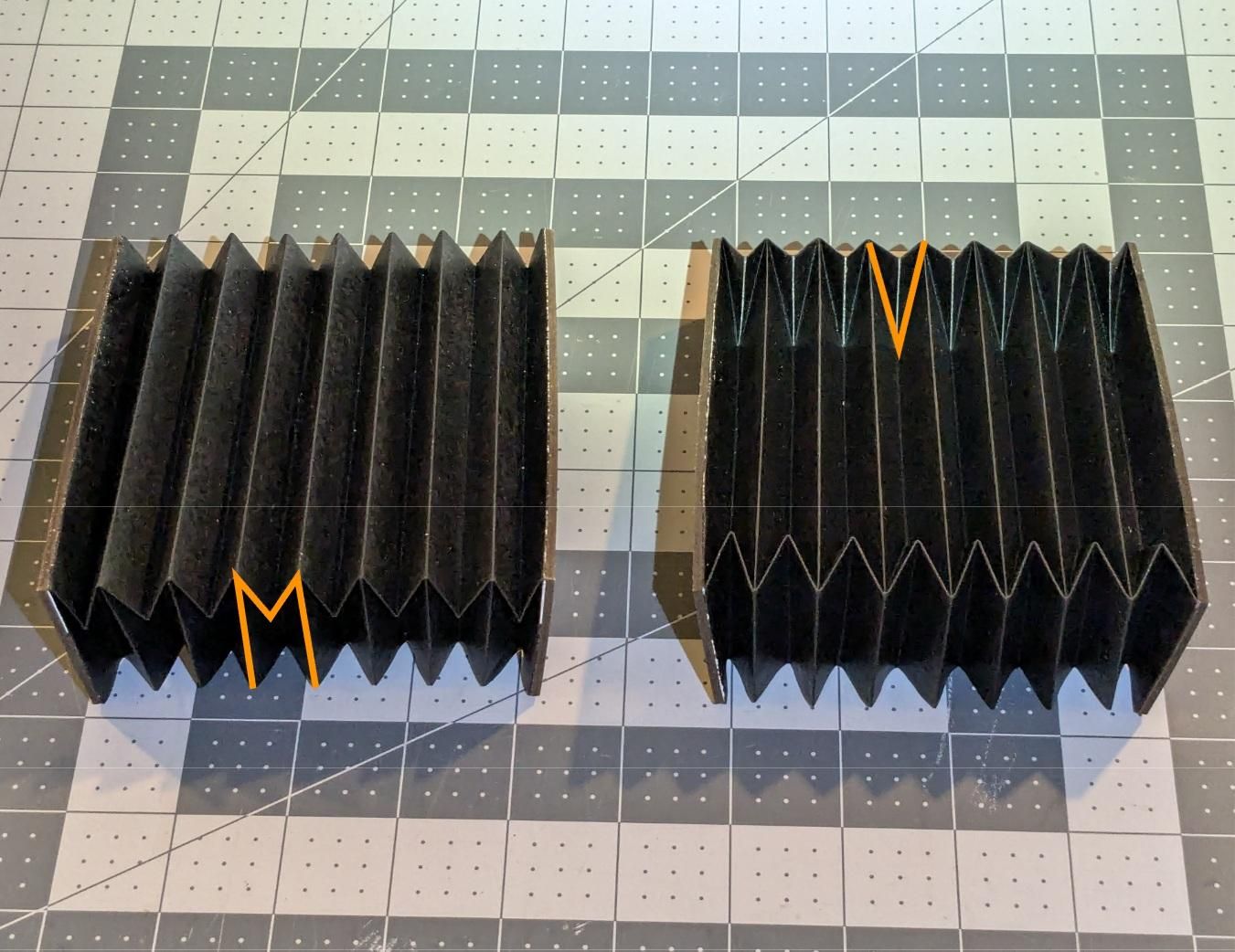
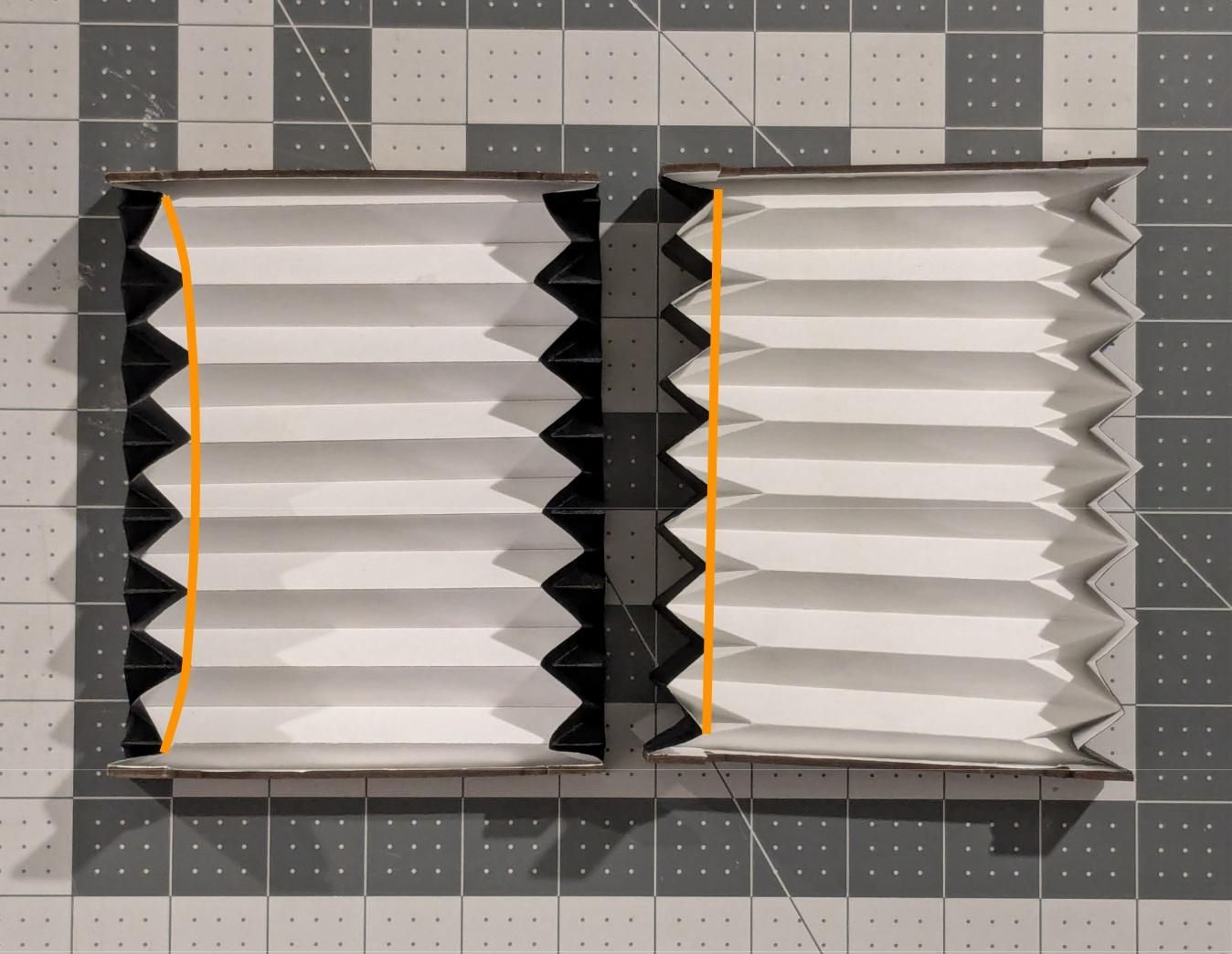
The standard bellows fold is what I call “M-fold”. It is easy to make, but has the tendency to buckle inwards when stretched.
Then I discovered a more optimal fold, which I call “V-fold”, where the creases meet at 55.14 degrees instead of the standard 90. There is a whole scientific paper and a patent from 30 years ago https://patents.google.com/patent/US6054194A/en describing why it retains its shape better during stretching. The downsides are that it is harder to make, and it protrudes out in the corners.
Supplies
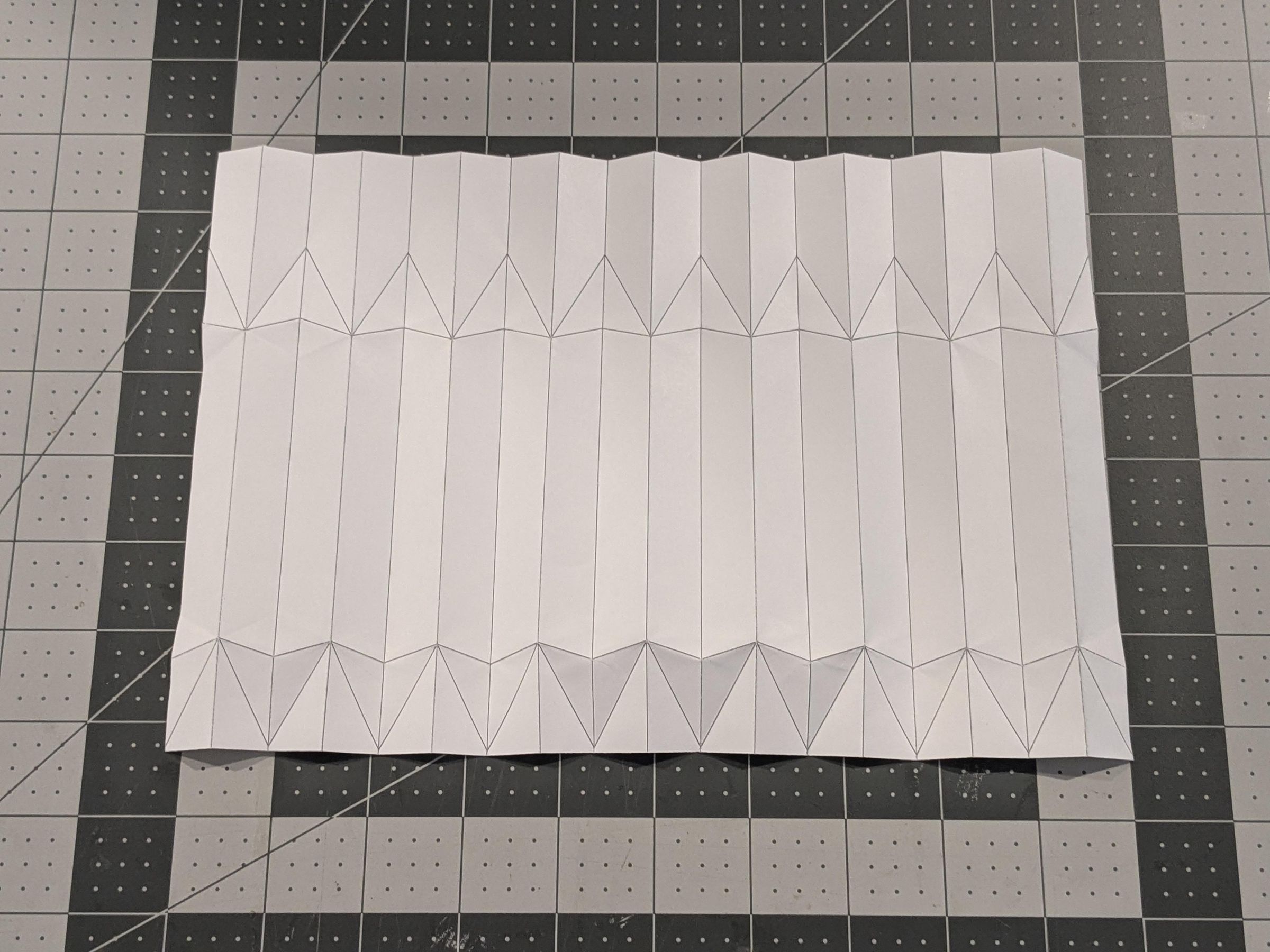
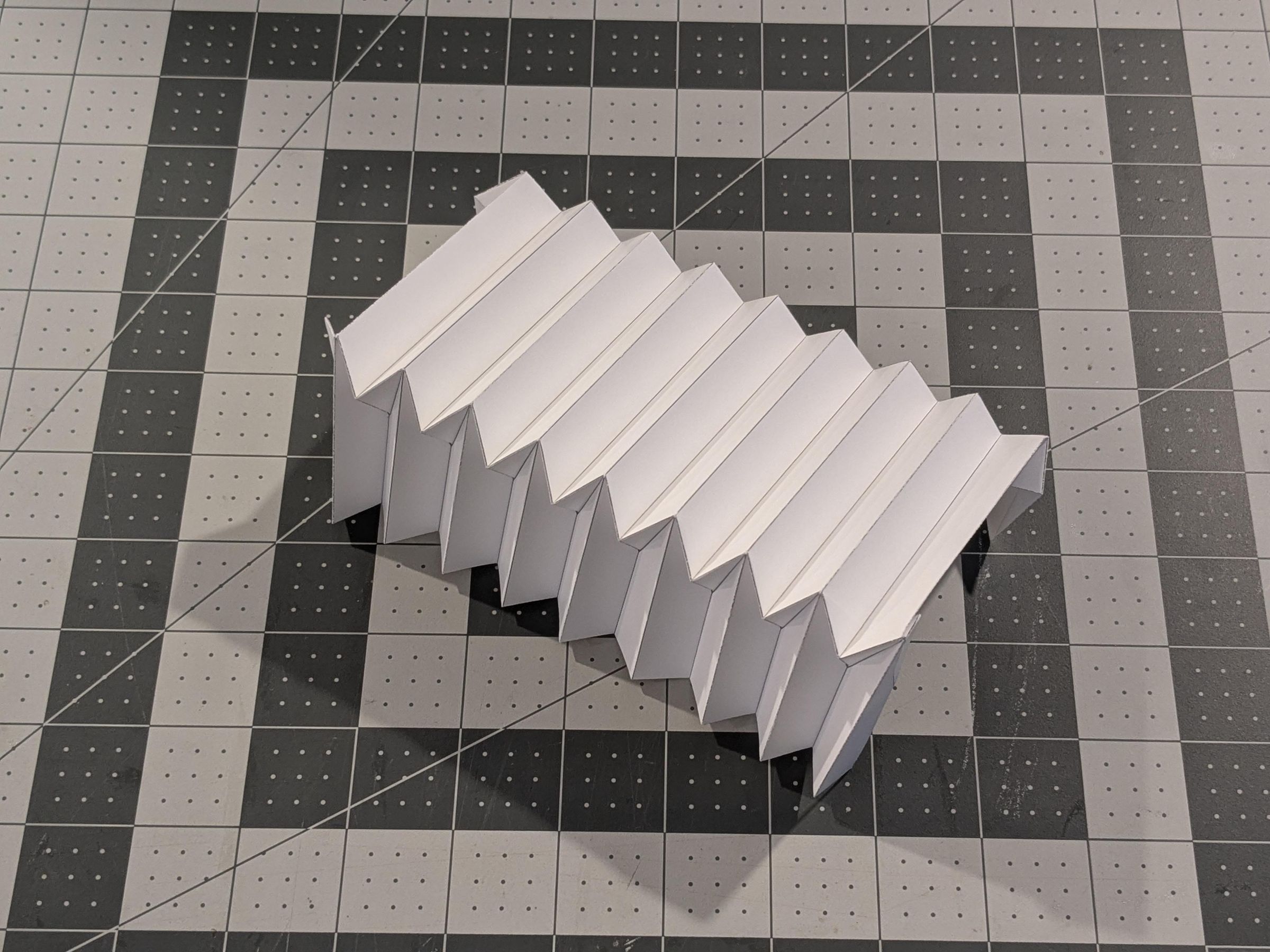
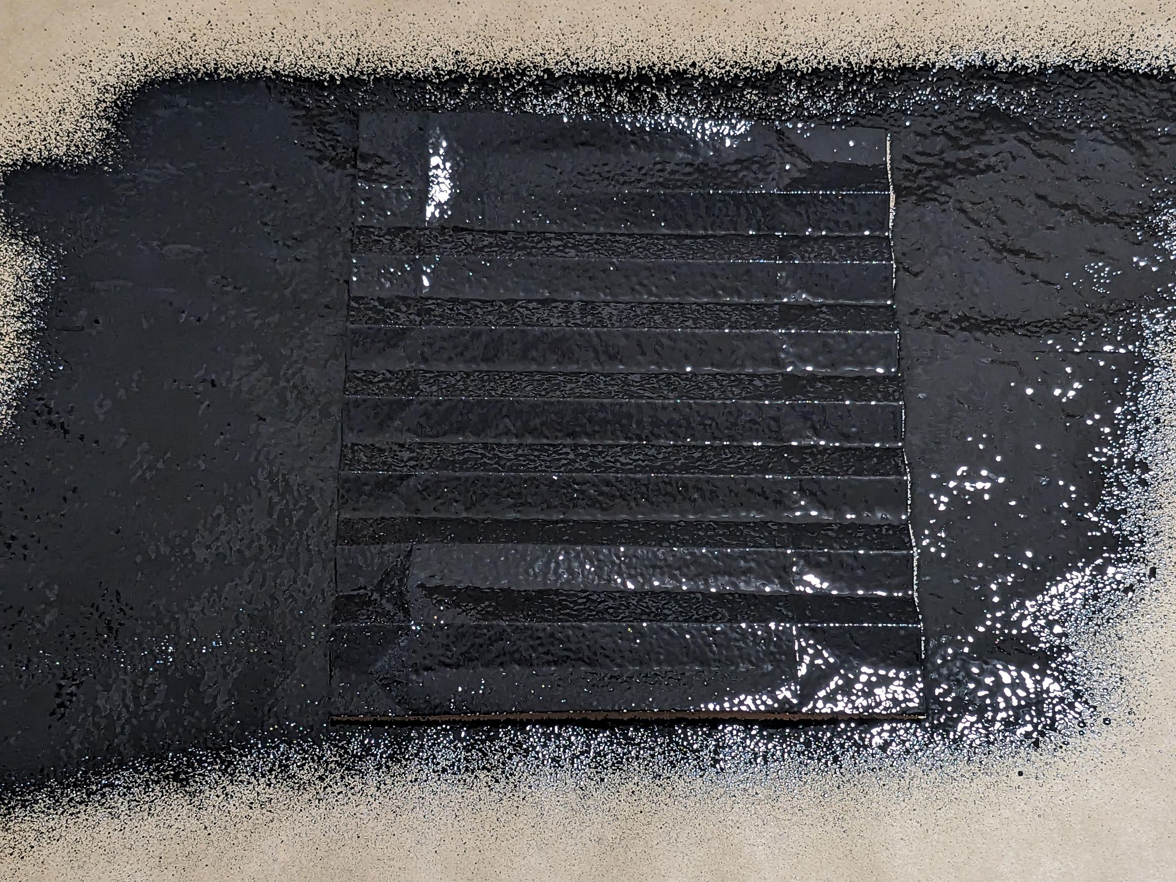
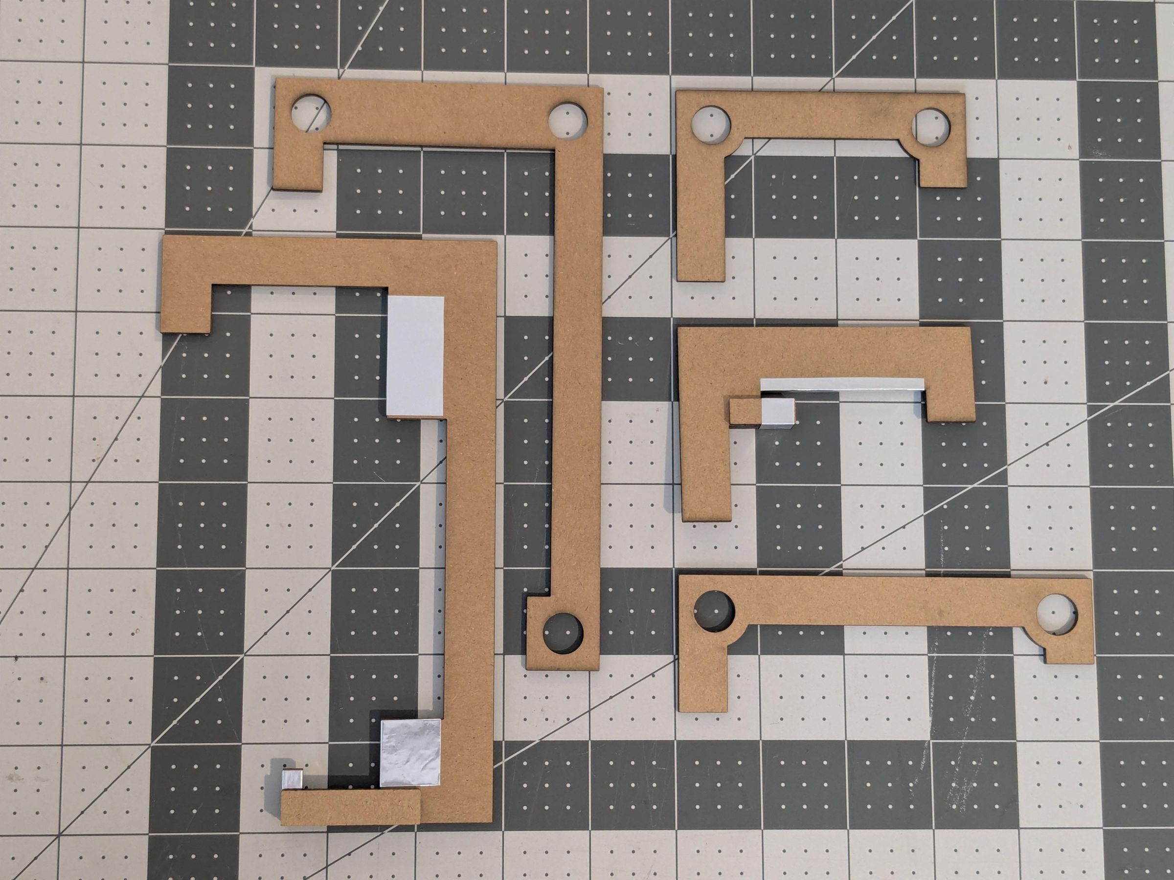
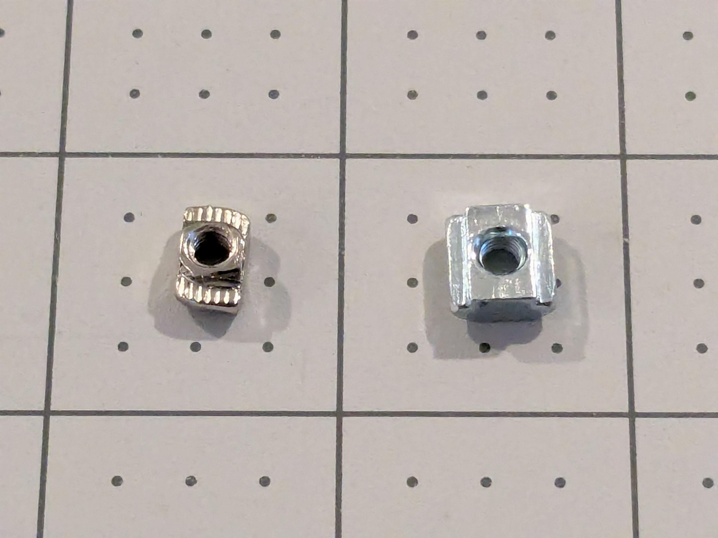
For the bellows I start with plain 28lb paper. The X axis needs “legal” sheets 8.5" x 14" due to the greater width. The Y and Z use regular “letter” sheets 8.5" x 11".
I print the pattern on the sheets, cut them, score them, and fold them.
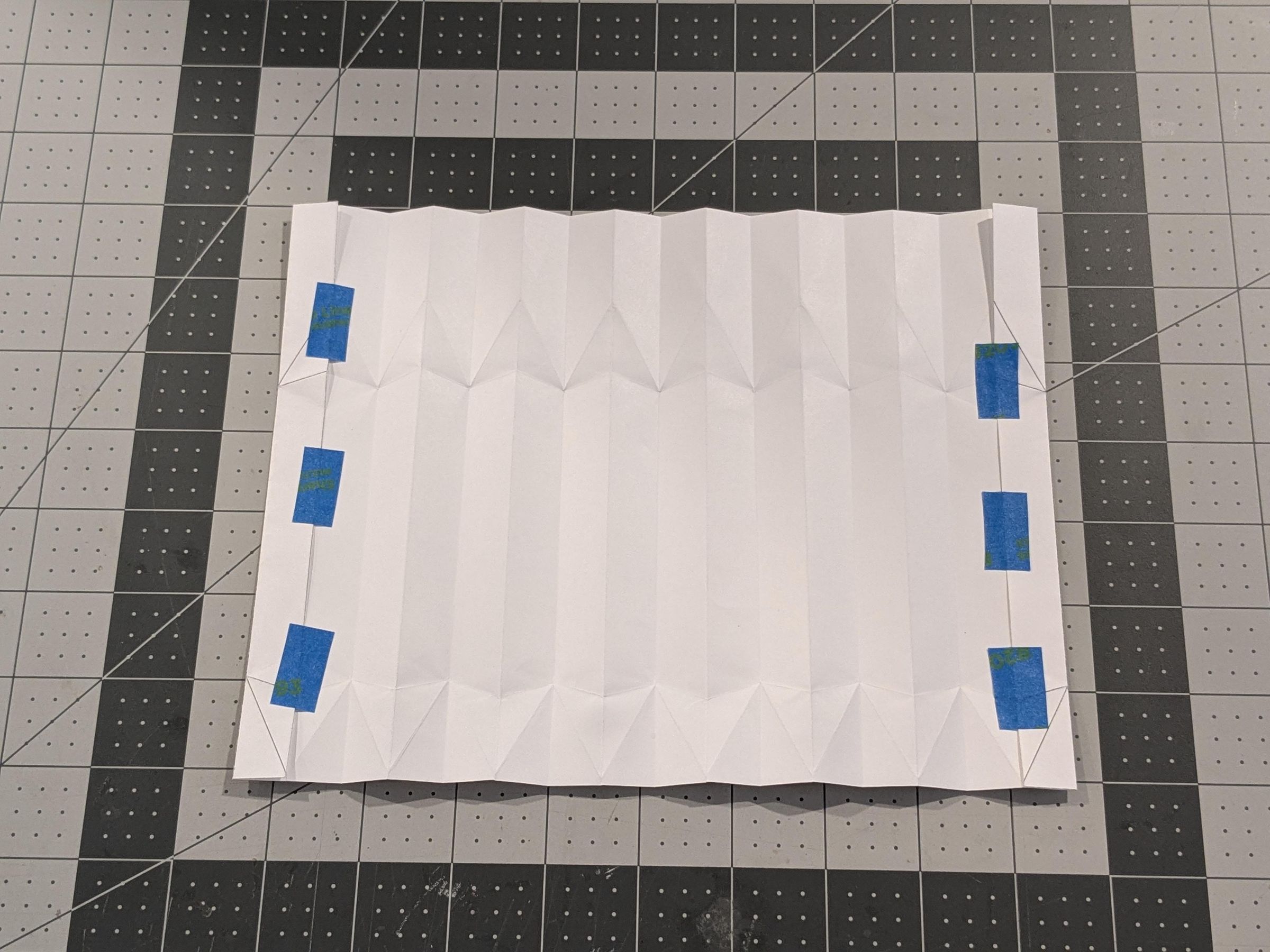
Then the sheets are unfolded and sprayed with Flex Seal. I keep the first and last stripes folded and taped behind, as they will later need to be glued to the ribs.
The ribs are made of 2mm cardboard on a laser cutter. Some parts are reinforced with extra cardboard strips. The edges that will touch the metal frame are further protected with aluminum foil.
Besides the bellows themselves, there are multiple 3d-printed parts to connect them to the frame. I used PETG with 0.2mm layer height.
The plastic parts connect together mostly with M3 screws and square nuts. Some pieces need 12mm magnets with 2mm and 3mm thickness. In practice the magnets are 1.8mm and 2.8mm thick, you may need to adjust the models to fit your particular magnet size (both in terms of thickness and radius).
Some parts are mounted onto the aluminum extrusions using drop-in T nuts. They are a PITA to use as they keep falling off or fail to twist into place, but they eliminate the need to remove the end plates to insert proper T nuts. Next time I am rebuilding the machine I may replace them with full-sized nuts.
For gluing paper and cardboard I use Aqua Mono liquid glue. For the magnets I use medium viscosity CA glue.
Below you can find all of the design files - the paper patterns and all 3d models. I am including an STL file for each model, as well as one STEP file that includes all the parts. From the STEP file you can also see how the parts fit together.
Downloads
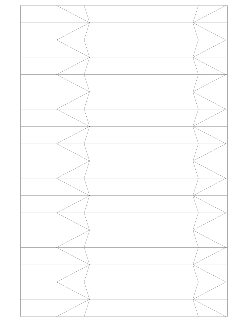


The X Axis Covers
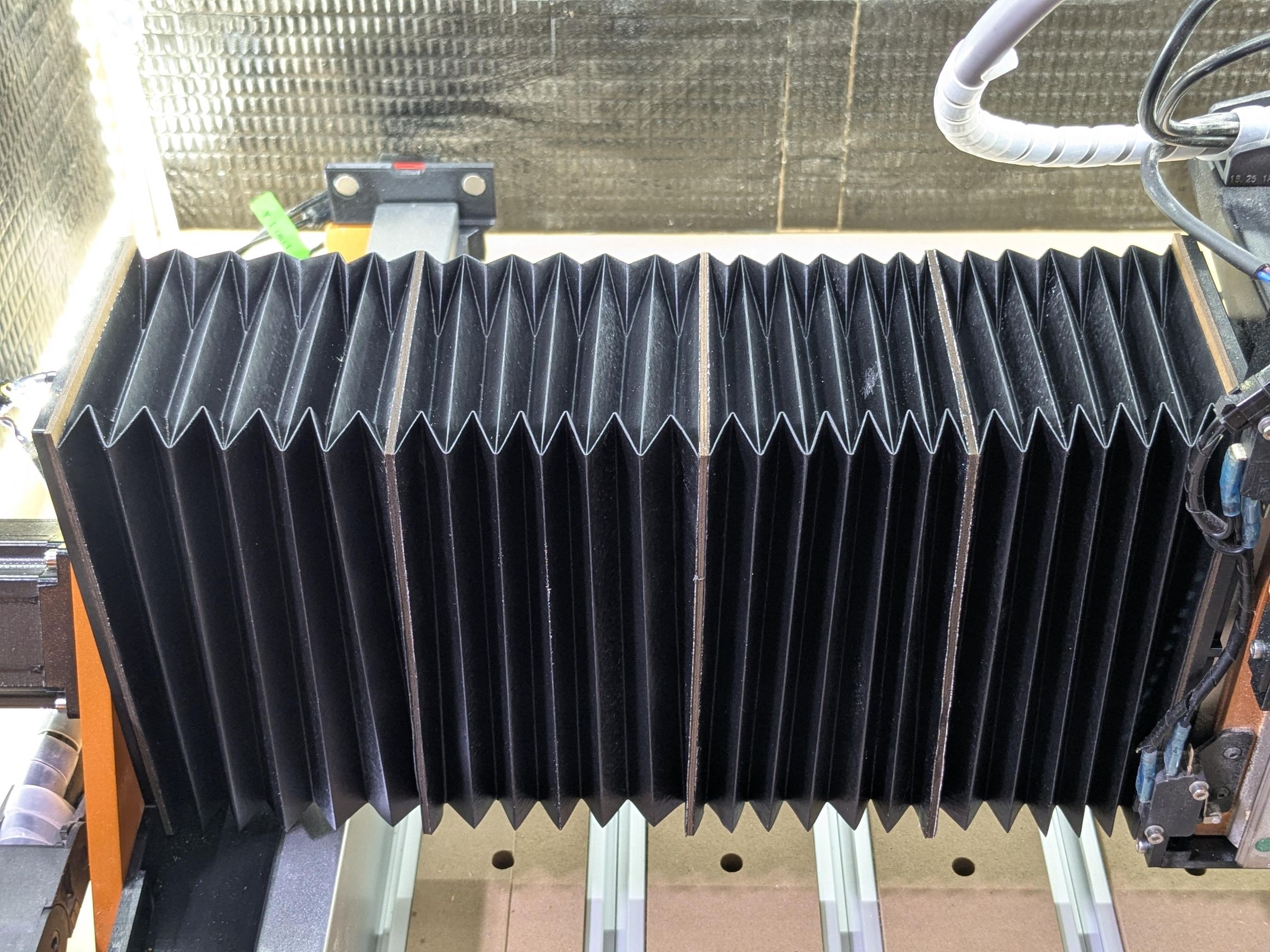
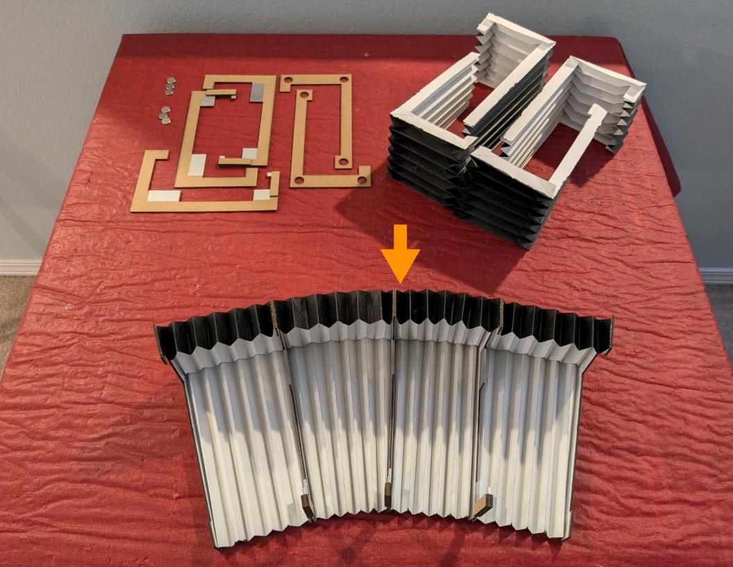
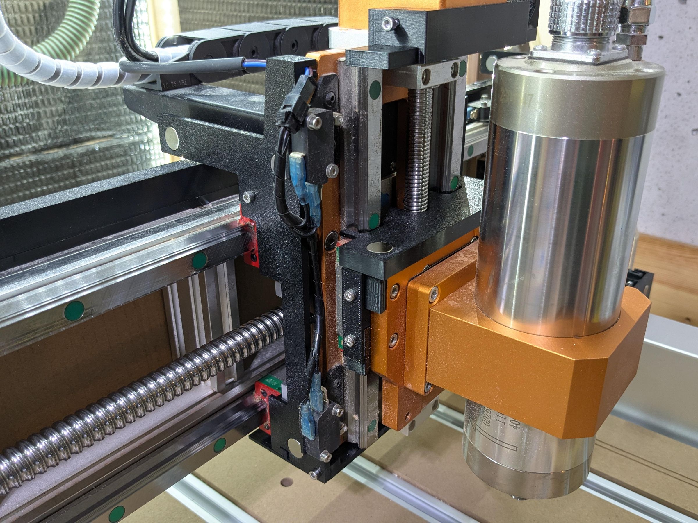
The X axis needs 2 bellows, each made of 4 segments, 3 middle ribs, 2 end ribs, and 6 magnets.
The middle ribs have an extra notch that rides inside the bottom slot of the X axis extrusion. This prevents the covers from buckling out when compressed.
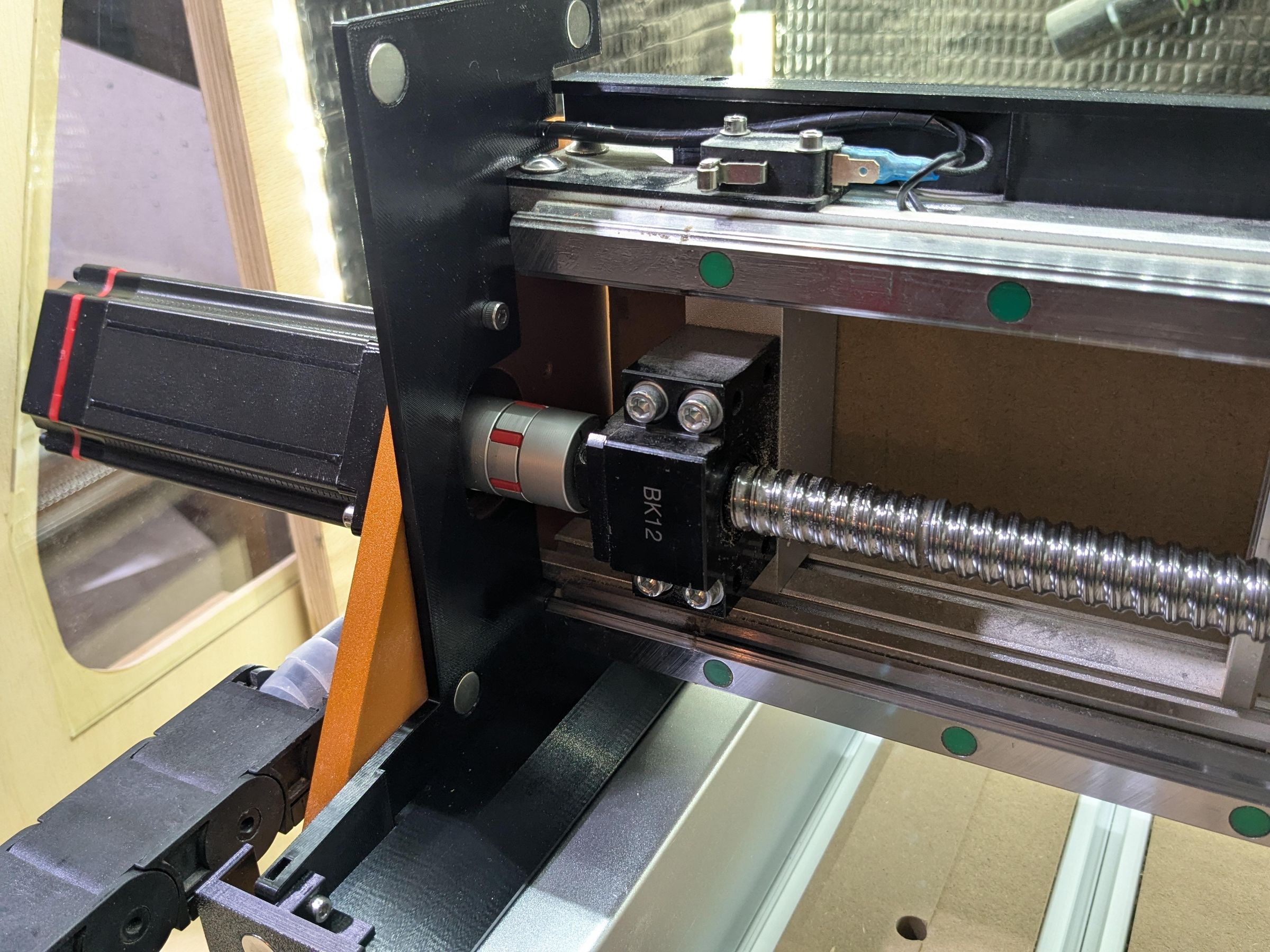
The bellows are attached to the gantry and to the frame with 3d-printed parts.
The 2 side plates are bolted to the Y1 and Y2 carriages with M4 screws, using existing holes. They are further secured at the bottom with either the optional Y axis plates or the replacement brackets. The left plate has a slot for routing the X limit switch cable.
The 2 middle plates are linked around the Z assembly with a top and bottom connector. The left plate has a hook to keep the Z limit switch cable out of the way.
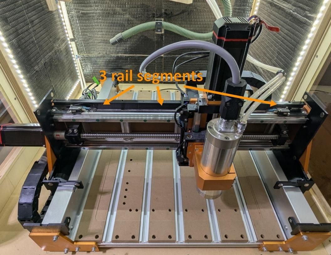
There is a plastic rail that is bolted on top of the X axis to guide the ribs. It is constructed from 3 segments. The middle segment has a magnetically attached removable part to make it easier to install and remove the bellows.
In case the magnets turn out to be not strong enough, I designed clips x_axis_clip_end and x_axis_clip_mid to provide extra support. They are sized for 2mm cardboard. You may have to modify them if using a different thickness.
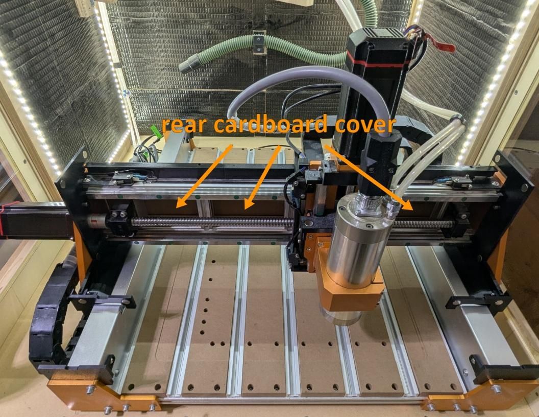
In addition to the bellows on the front of the X axis, I have a piece of cardboard on the back. It is permanently mounted to the vertical extrusions with M3 screws and T nuts. It reduces the amount of dust entering from behind.
The Y Axis Covers
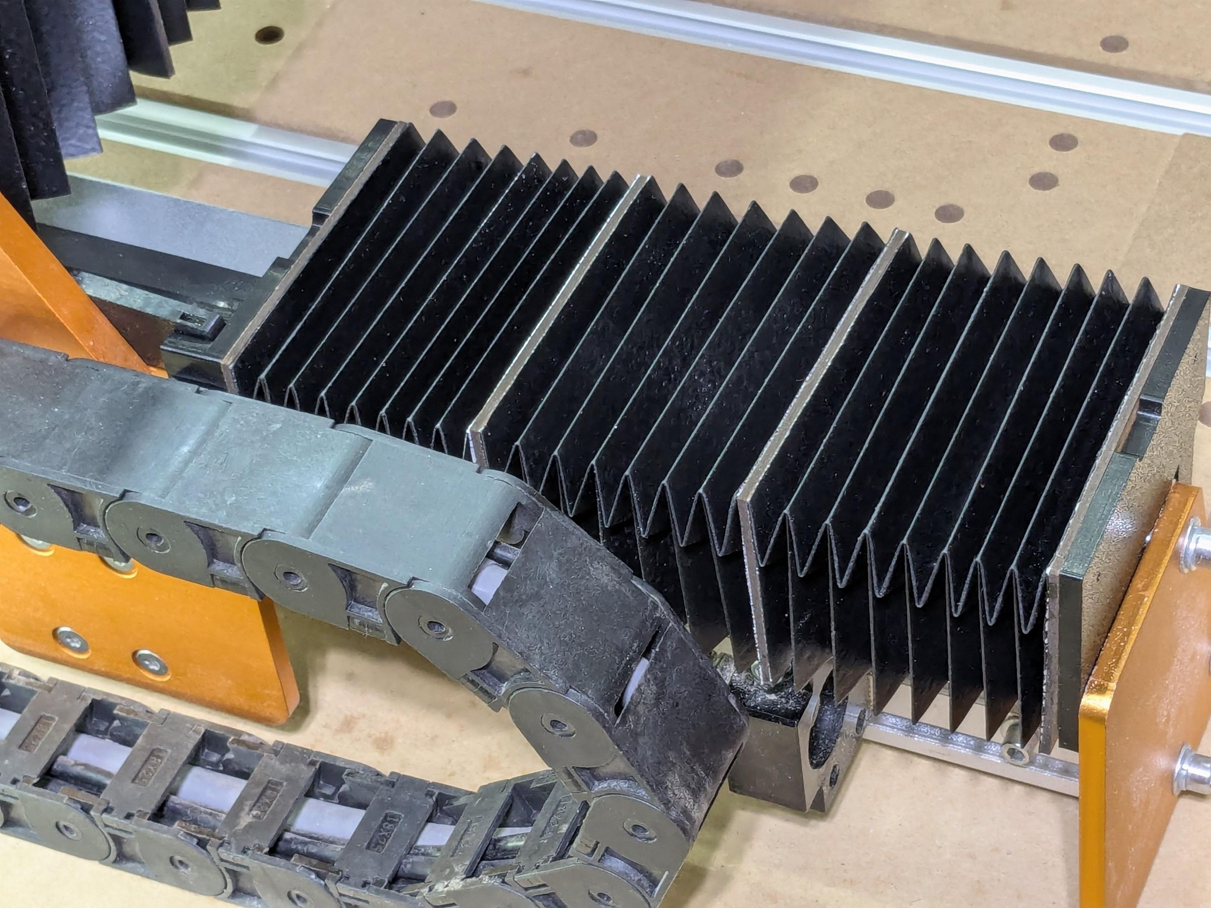
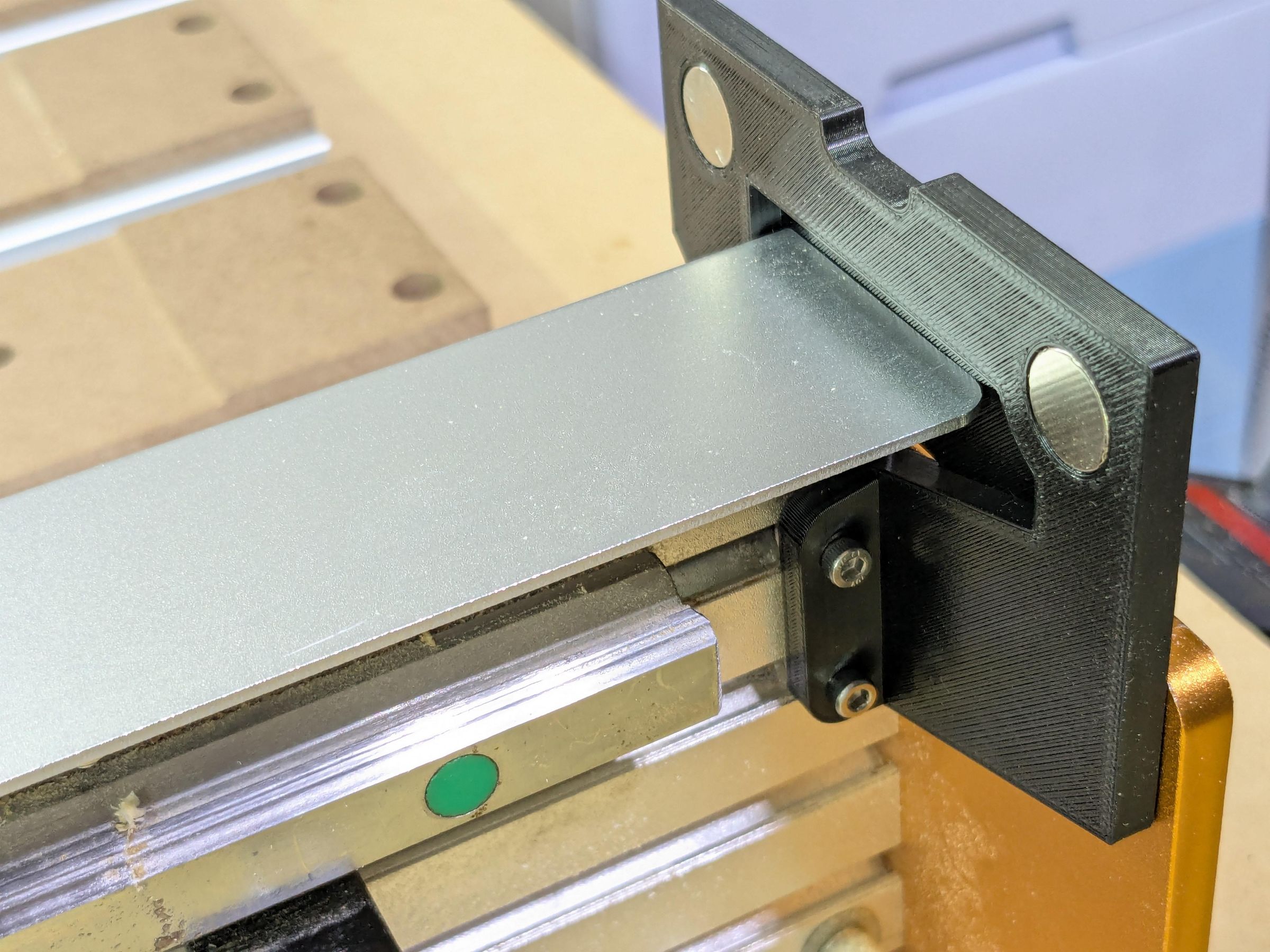
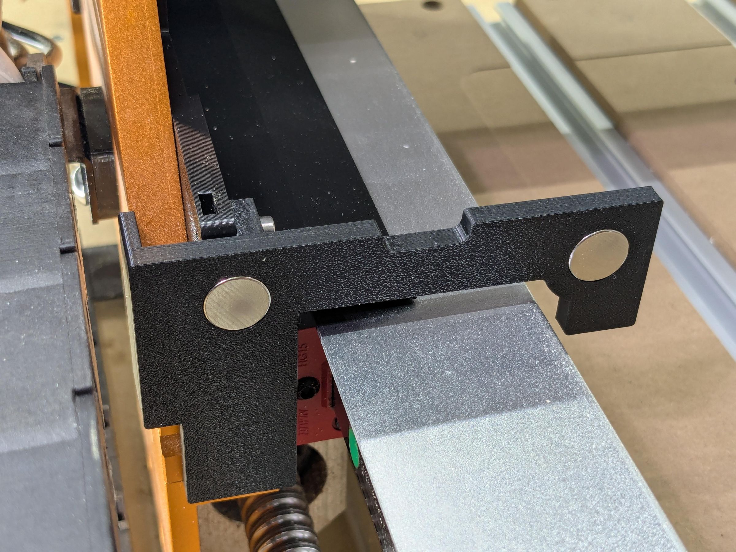
The Y axis needs 2 or 4 bellows, each made of 3 segments, 2 middle ribs, 2 end ribs and 4 magnets.
The middle ribs have a slot that rides on the existing aluminum dust guards. This stops the covers from buckling up when compressed.
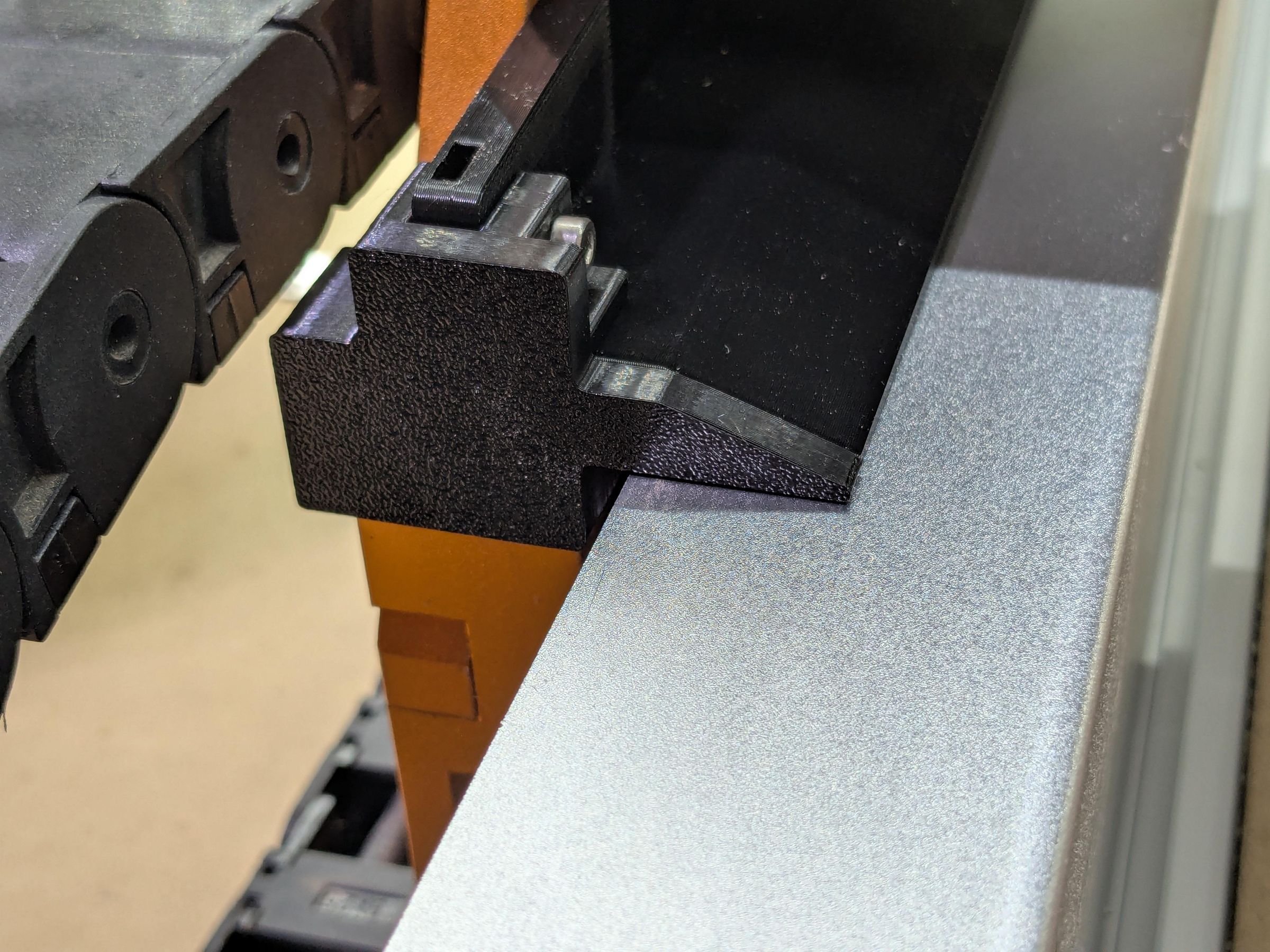
The bellows are attached to the frame with plastic parts y_axis_plate1, y_axis_plate2, y_axis_plate3 and y_axis_plate4.
Note: The provided models are for the right side. Mirror them and print them again for the left side.
The front and rear plates are attached to the outside with T nuts and to the inside using the existing screws from the aluminum guards. The aluminum guards need to be removed to install the rear piece y_axis_plate4 in case you choose to have covers in the back. The rest of the parts can be attached without removing anything.
y_axis_plate2 and y_axis_plate3 are attached to the X axis side plates with M3 screws and square nuts.
The left dust cover gets quite close to the drag chain and can rub into it. I added 5mm spacers to move the drag chain away. This is not strictly necessary, as there is very little contact. If you decide to do this, you will need to replace the existing 6mm bolts with 10mm or 12mm M5 bolts. There are two copies of the spacer, one for each end of the drag chain.
Note: The Y dust covers are designed to be optional, both in the front and in the back. The parts y_axis_bracket2 and y_axis_bracket3 can be used instead of y_axis_plate2 and y_axis_plate3 to secure the X plate to the frame if the front or the rear cover is missing.
Warning: Due to the X axis side panels being slanted backwards, there is far less space behind than in the front. To have dust covers in the rear of the Y axis, you will need to reduce the Y travel by about 40mm and move the rear limit switch forward by the same amount. I myself decided to forego the rear covers because there is significantly less dust accumulating there.
The Z Axis Covers
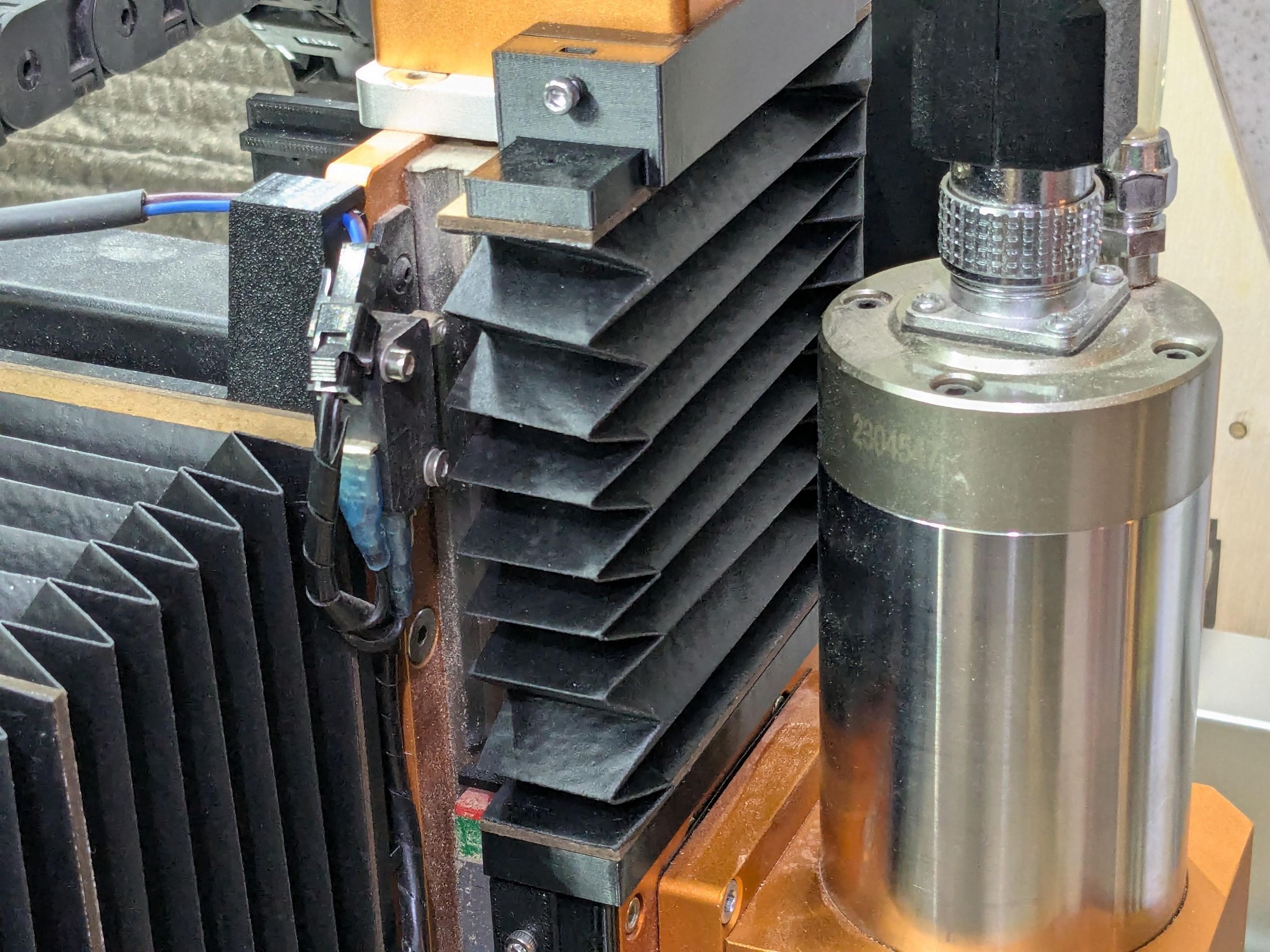
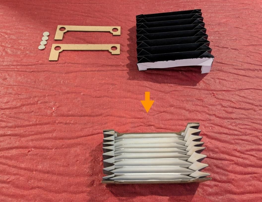
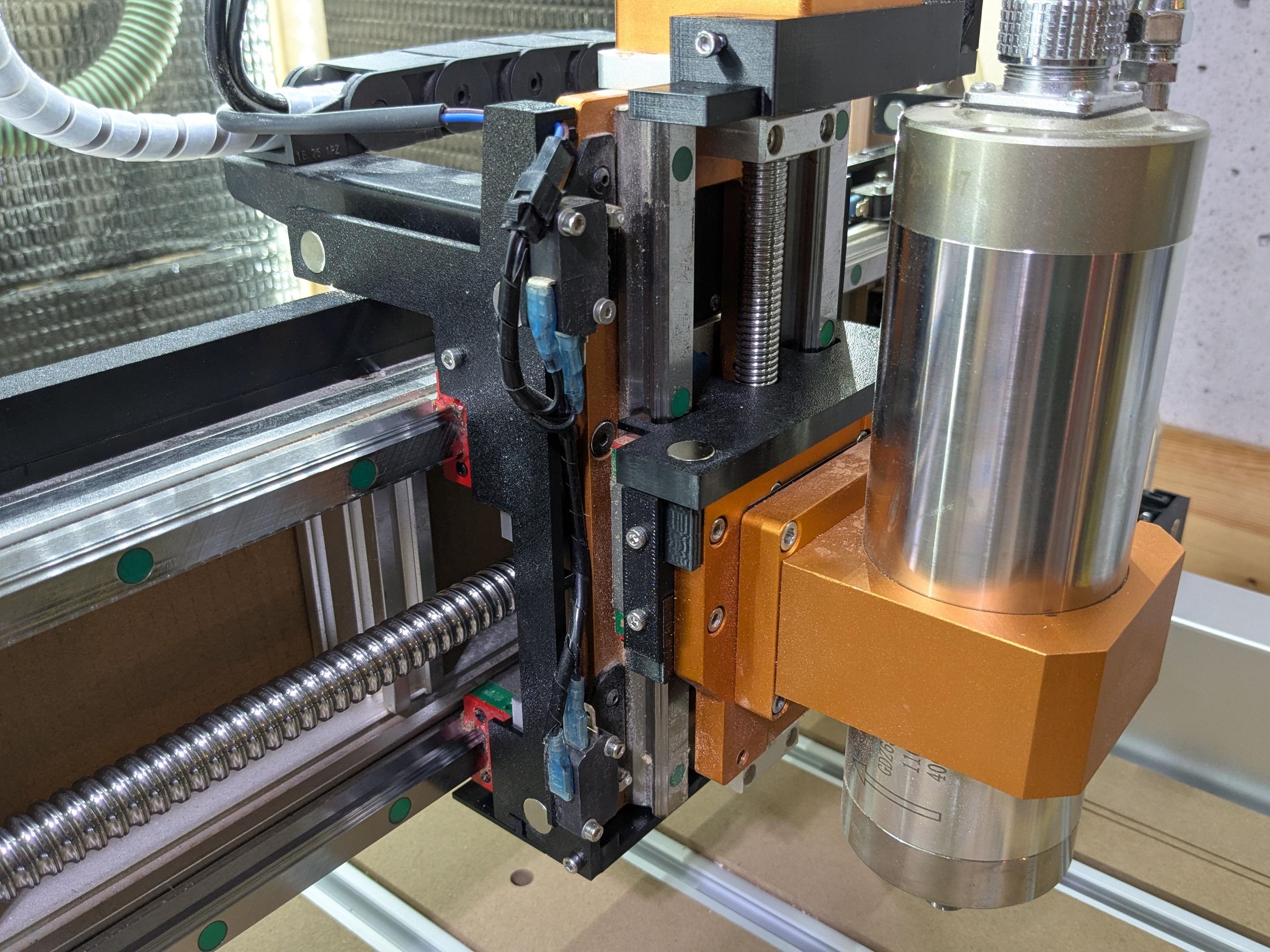
The Z axis is the simplest because it has the shortest travel distance. It has only one segment.
The top plate is squeezed onto the Z motor mount with two bolts from the sides and held by friction. The rest of the parts hug the Z carriage and provide some dust protection to the bearings from all sides.
There are 2 variants of the top plate z_axis_plate1 - one for the 52mm spindle and one for 65mm and up. The reason is that the original 52mm spindle has a shallower mounting bracket that puts it closer to the surface.
Unfortunately, there is no way to add a dust cover to the bottom of the Z assembly. The carriage travels beyond the frame, so there is no room for any additional parts.
Due to the shorter stretch distance, the Z axis can work with either the M-fold or the V-fold. Use z_axis_dust_cover.svg for the V-fold and z_axis_dust_cover_M.svg for the M-fold.
Final Thoughts
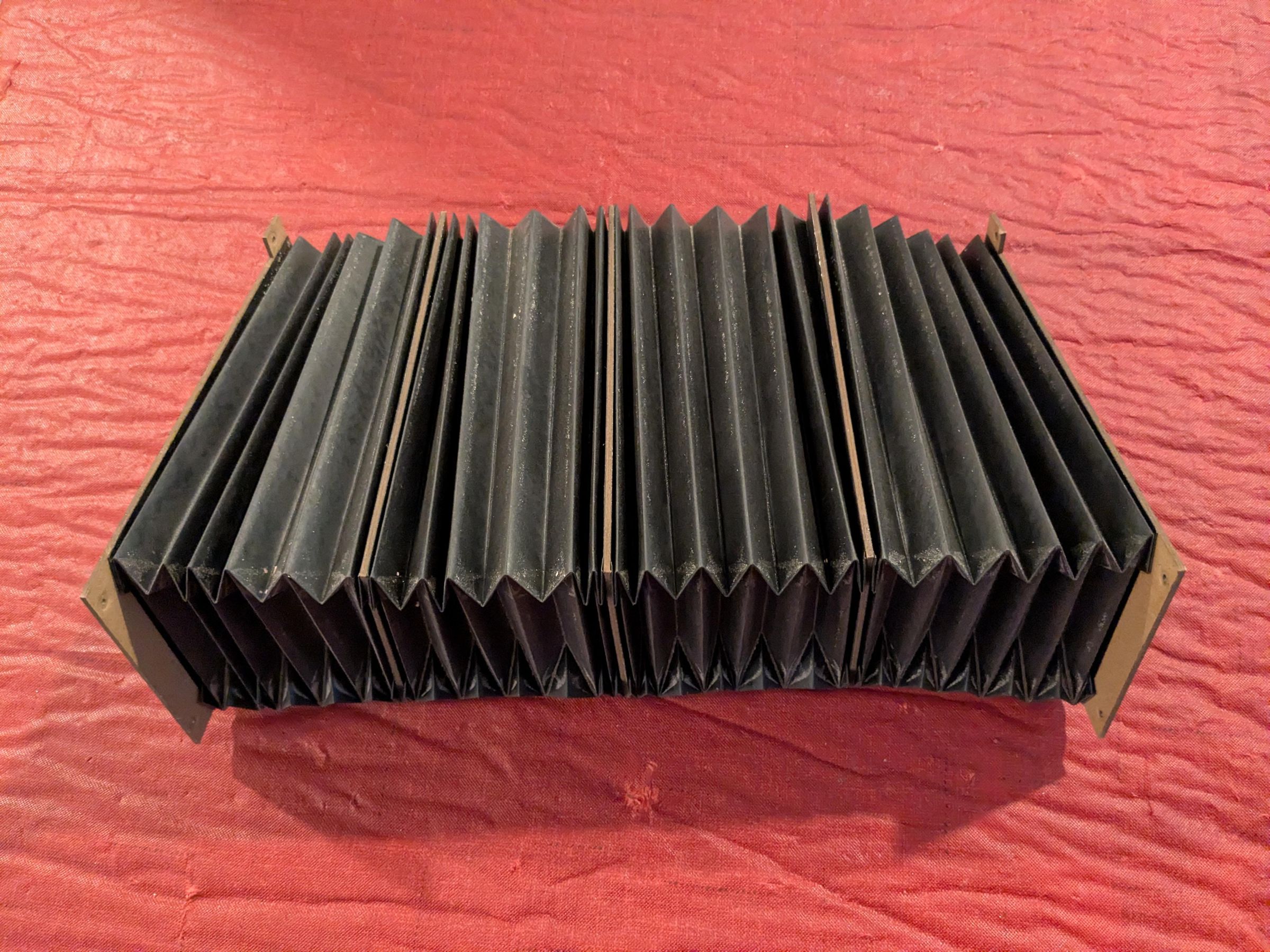
Durability
I’ve had the X and Z axis covers for about 3 years of moderate use. Besides just getting dirty, they show only a few signs of wear and are still intact.
I believe the Flex Seal sprayed paper is adequate for this purpose.
Caveats
While the dust covers keep the insides significantly cleaner, they have a few downsides.
- They are not perfect. Some dust still manages to get through. The bottom of the X axis is particularly vulnerable. It is not possible to extend the covers below the axis without losing at least 20mm of clearance, which is quite limited to begin with. One idea I have is to mount a horizontal piece of cardboard right below the ribs to cover the gap. It will still reduce the clearance, but only by a little bit
- The extra pieces mounted to the frame make it harder to access the rails for cleaning and lubrication. The first version of the X axis covers used screws instead of magnets, making it even more time-consuming to take off. I am hoping the new magnet attachments simplify the maintenance process
- The bellows construction process is quite tedious. Printing, scoring, folding…
- Even after doing a bunch, it still takes me 40-45 minutes to process one single sheet. This doesn’t include the spraying, drying time, and the final glue-up. And during my experiments I had to do this a few dozen times
- Since all sections of one cover are permanently glued together, if one part gets damaged, everything will need to be remade (see #3). Possibly each section can have its own independent cardboard ribs, which connect with magnets or clips so they can be individually replaced
- The combination of paper and rubber may not be suitable for cutting metal, in case there are hot chips flying around. The bellows material could be flammable, and it could release toxic chemicals if it catches fire
Alternative materials
The Flex Seal spray produces nasty fumes. Proper ventilation and PPE are required. It is available also in liquid version that could be applied with a brush. It may be safer and more economical that way. I have not tried it though.
In the interest of fairness, I also have not tried paper on its own without the coating. It may be durable enough?
I did experiment with different paper thicknesses before settling on 28lb weight. Thinner paper was tearing up when scoring, and thicker paper was cracking when creased. 28lb was the sweet spot for me.
There are types of specialty paper that are water-resistant and may work without an additional rubberized coating. This may be something to explore.
Someone had success using thin polypropylene sheets: http://www.franksworkshop.com.au/CNC/Bellows/Bellows.htm
There are even attempts to 3d-print bellows from TPU: https://www.youtube.com/watch?v=UFrWfnwD3aU
Note about the limit switches
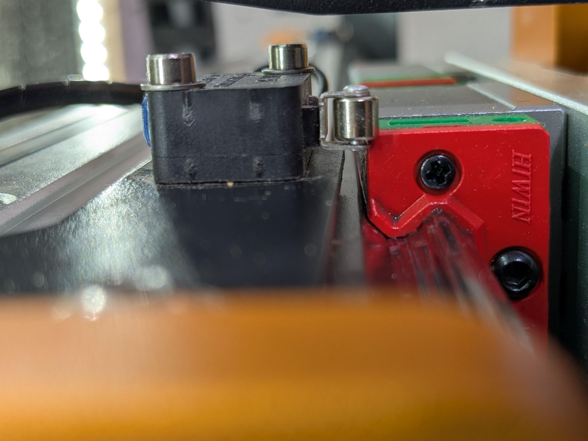
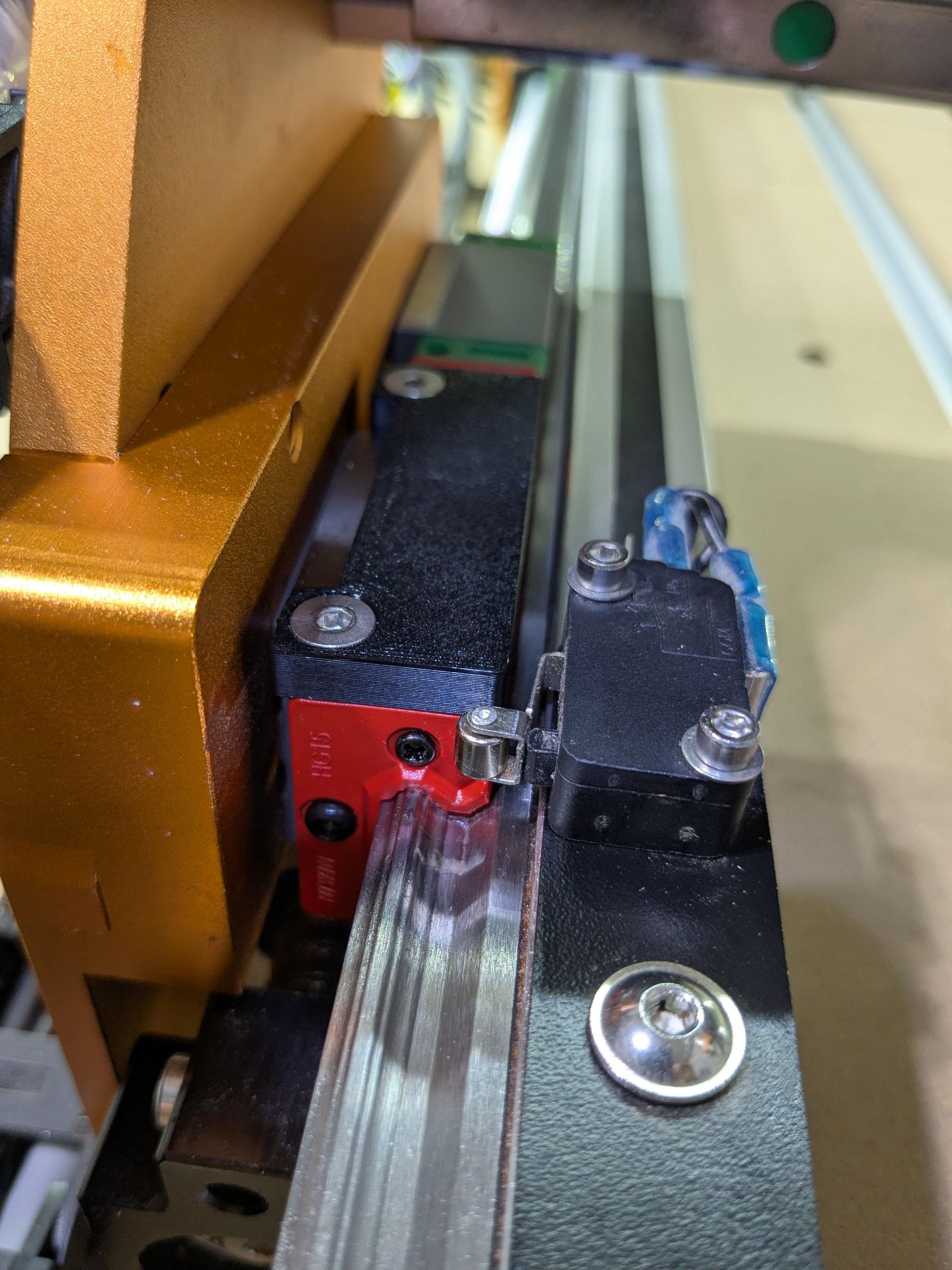
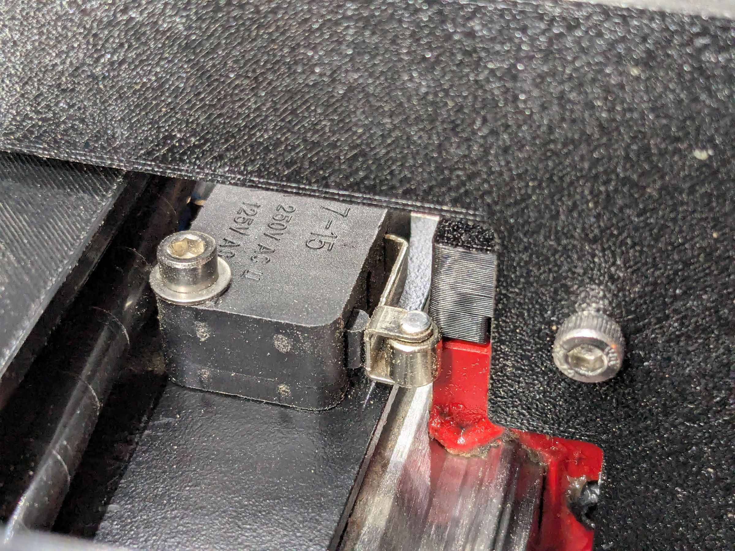
The X and Y limit switches on the FoxAlien Vasto don’t make good contact with the linear blocks. Only the corner of the switch roller connects with the body of the block, causing the lever to twist upwards. This results in some variance in the homing accuracy.
For the Y axis I designed an extra plastic riser that bolts onto the linear block. There are 2 holes on the block that are intended for 4mm grease fittings. I tapped them and attached the riser with M4x8 screws. It extends the contact area with the limit switch for more reliable and accurate homing.
For the X axis the top connector bracket x_axis_connect_top serves the same purpose.