ESP32 Pocket Multi-tool
by Adrian Pol in Circuits > Microcontrollers
3141 Views, 28 Favorites, 0 Comments
ESP32 Pocket Multi-tool
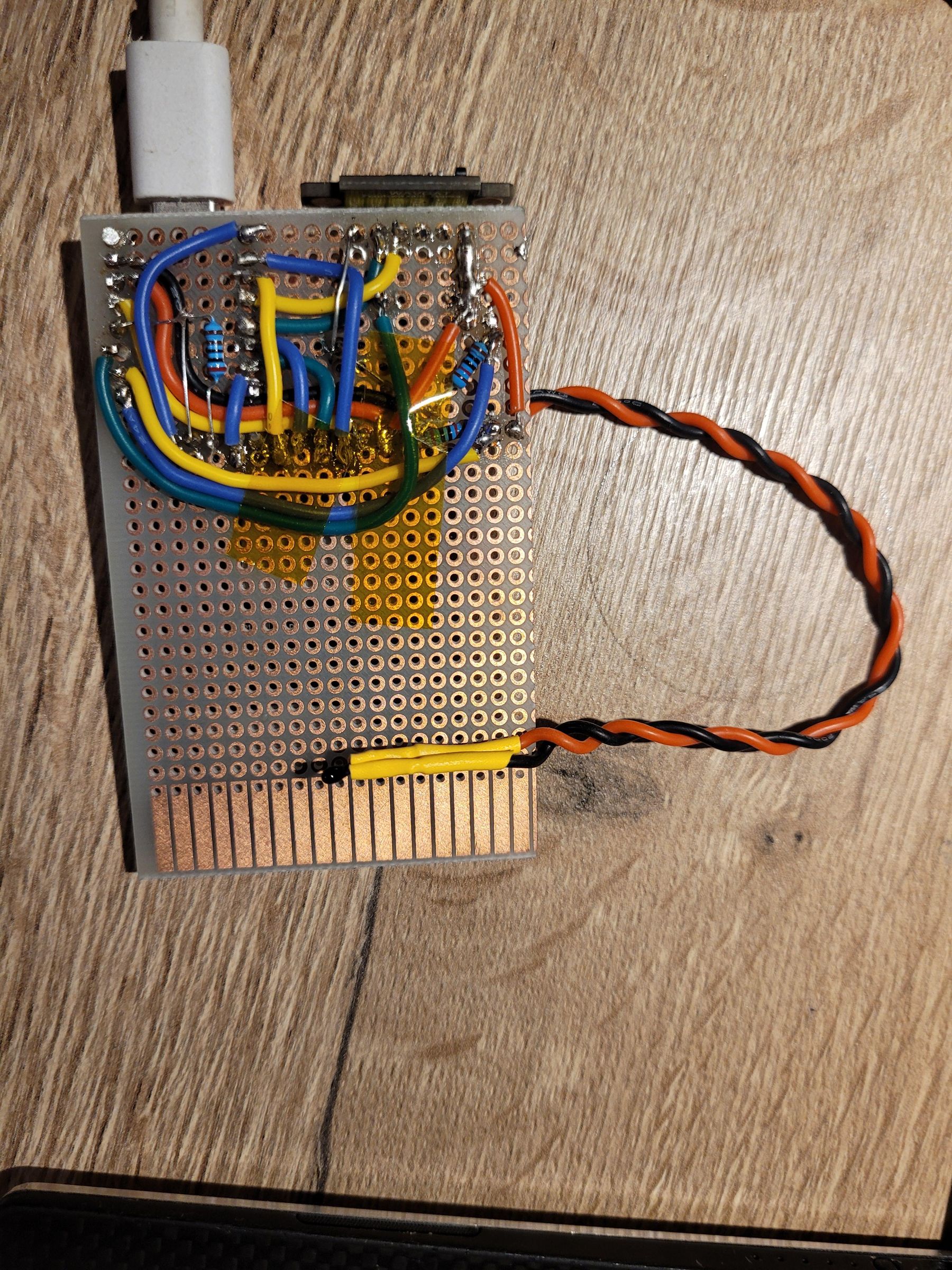
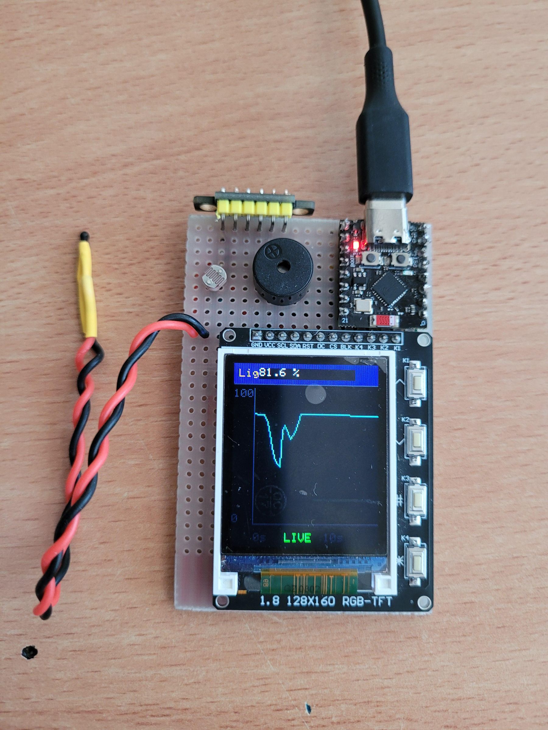
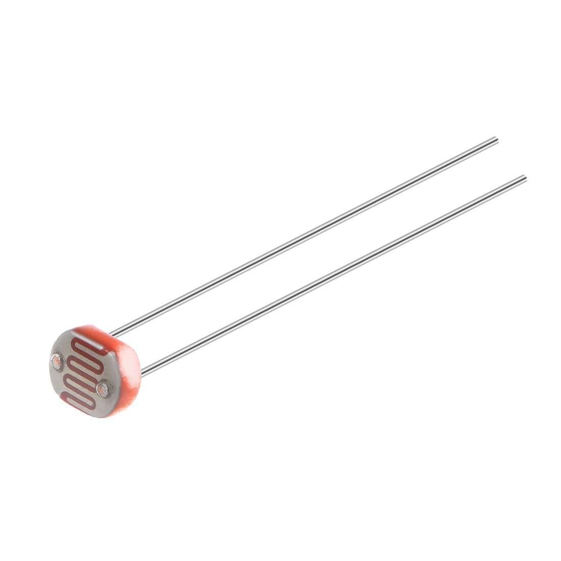
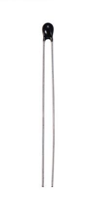
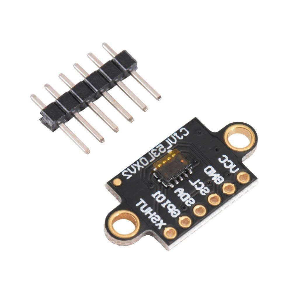
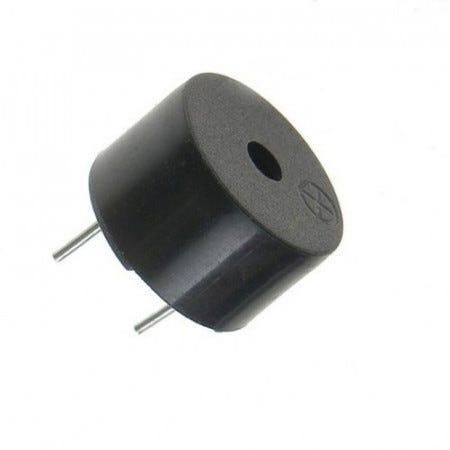
I often find myself in a situation, where I need to measure temperature, distance or just compare how strong are the light in a room. That is why I decided to build this multitool. It features a photoresistor, thermistor, time of flight sensor (for measuring distance), passive buzzer for sounds, 1.8 inch tft lcd with 4 buttons, and an esp32-c3 supermini microcontroller. It also has some small fun games when you are bored.
Supplies
Components:
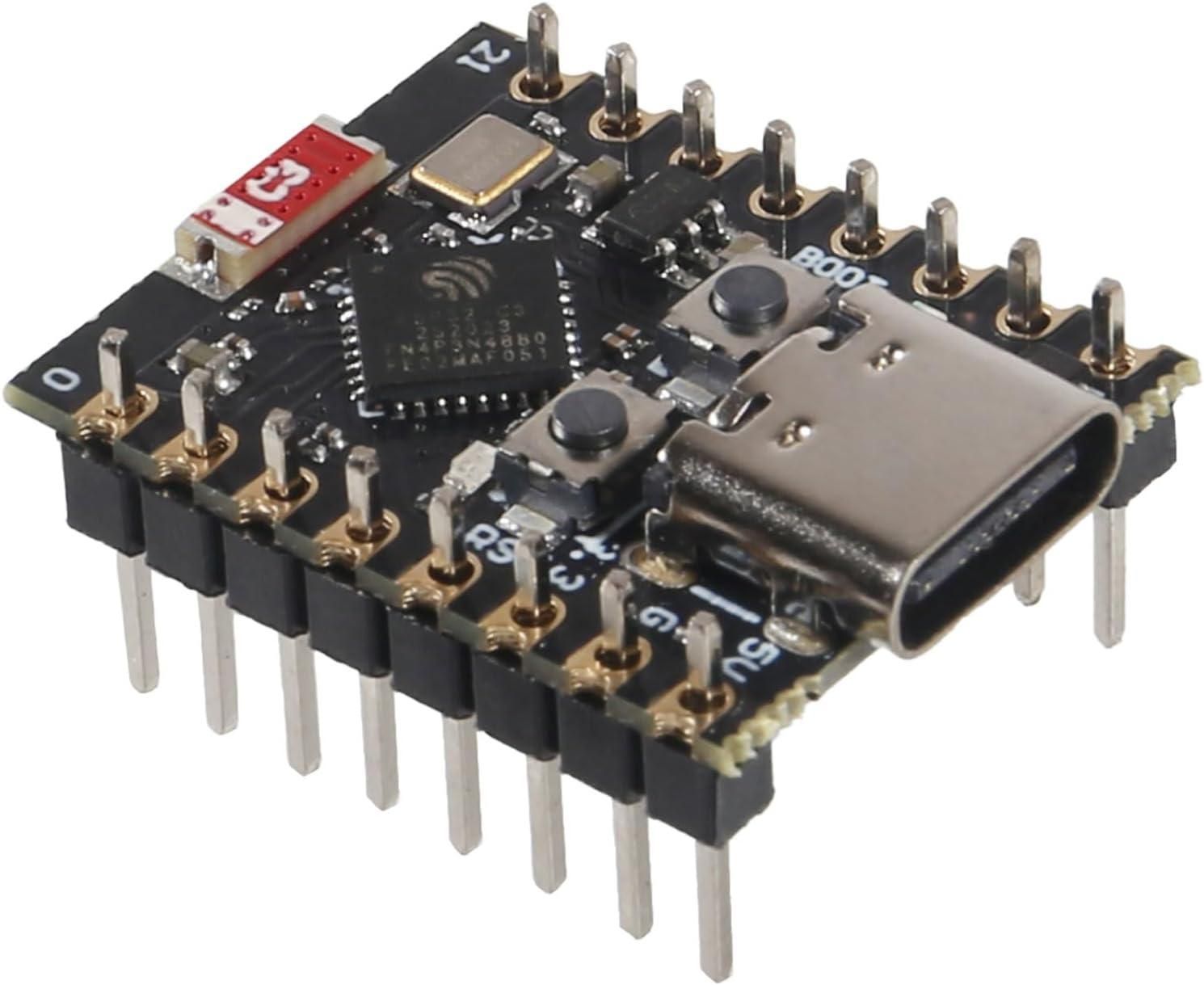
- ESP32-C3 supermini
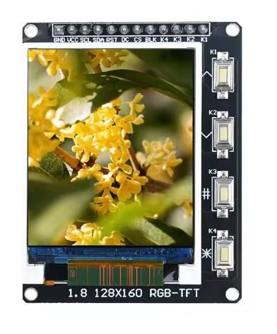
- 1.8 inch tft lcd ST7735S with 4 buttons
- Photoresistor
- Thermistor
- VL53L0X ToF sensor
- Passive buzzer
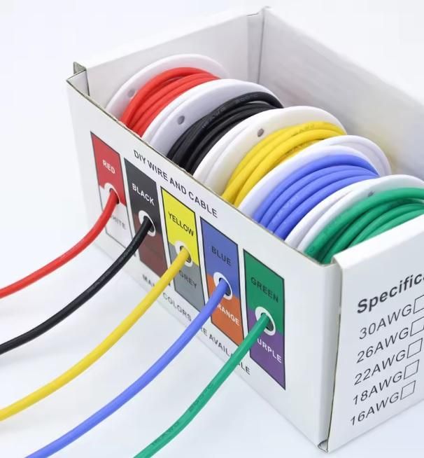
- Thin wires (I used 25AWG)
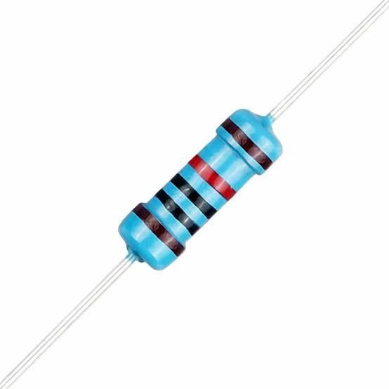
- 1 1kΩ resistor
- 2 10kΩ resistors
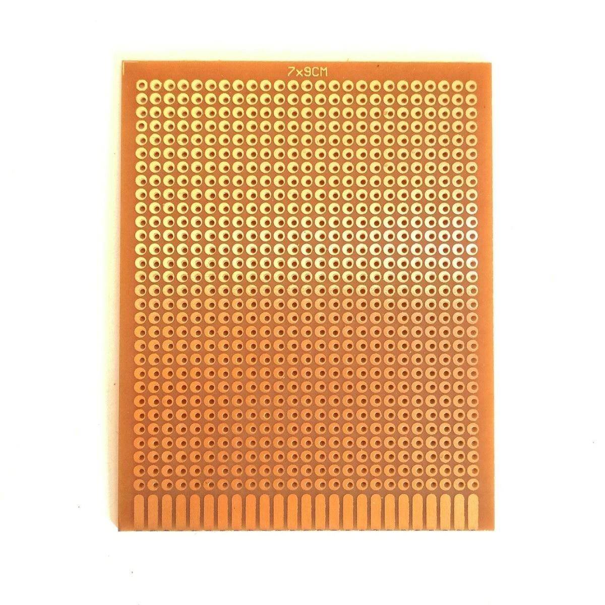
- Universal PCB
Tools:
- USB type C cable
- Soldering iron
- PC
Optional:
- USB power bank
Wiring
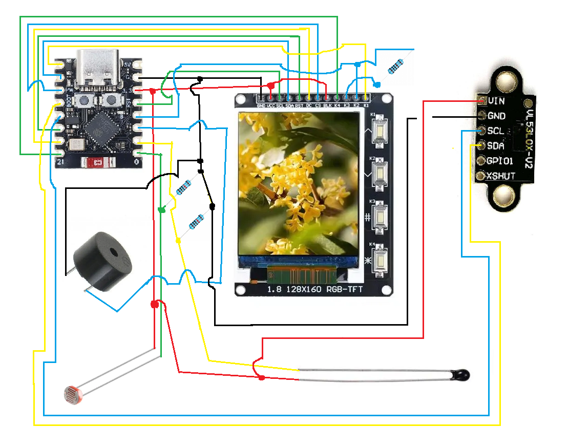
ESP32 pinout:
- GPIO 0: Photoresistor Analog Input
- GPIO 1: Thermistor Analog Input
- GPIO 2: Passive Buzzer Output
- GPIO 3: Buttons K2 & K3 (Resistor Ladder Input)
- GPIO 4: ST7735S TFT Screen SCK (SPI Clock)
- GPIO 5: Button K1
- GPIO 6: ST7735 TFT Screen SDA
- GPIO 7: ST7735 TFT Screen CS
- GPIO 8: VL53L0X sensor SDA
- GPIO 9: VL53L0X sensor SCL
- GPIO 10: ST7735 TFT Screen RST
- GPIO 20: ST7735 TFT Screen DC
- GPIO 21: Button K4
The ESP32-C3 supermini has a tiny footprint with only 13 exposed gpio pins. I didn't manage to fit photoresistor, thermistor, SPI screen, ToF sensor, buzzer, and 4 buttons to only 13 gpio pins. That is why buttons K2 and K3 share one gpio pin using a resistor ladder. When button K2 is pressed it pulls gpio 3 directly to ground and when button K3 is pressed it connects gpio 3 to ground through a 1kΩ resistor so the ESP32 can detect witch button was pressed. The 10kΩ resistors are there, so the photoresistor or the thermistor work as a voltage divider based on the sensors resistance the voltage on the gpio pin changes, so the ESP32 can detect the value.Other I2C sensors can be added since they can share the same lines just be sure to include a 4.7kΩ pullup resistor if the sensor doesn't have one included.
Code for the ESP32-C3 Supermini
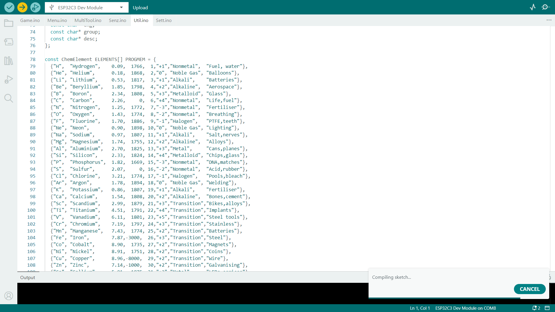
When you launch the code it shows a menu with these categories and functions for each:
- Sensors:
- Display all sensor data (in graph or digital readout in real time)
- Photoresistor, displays light level as percentage from the sensor
- Temperature, displays temperature form thermistor in degrees celsius
- Distance, displays distance from Time of Flight sensor in centimeters
- Utilities:
- Periodic table of elements, shows all 118 elements with some information about them
- Constans, list of popular constants like pi, speed of light in vacuum, Planck's constant, and so on
- Unit converter, convert common units of distance, volume, velocity and so on
- Calculator, simple calculator with plus, minus, multiplication, division, and decimal numbers
- Wi-Fi scanner, scans nearby Wi-Fi networks and displays their signal strength
- BLE scanner, displays Bluetooth devices in range
- Stopwatch, can track time and store laps
- Counter Timer, set a timer and after set time a buzzer will alert you
- Games:
- Simon, simple memory game
- Dino, a copy of famous chrome dino game
- Snake, a copy of snake game on old Nokia phones
- Flappy bird, copy of flappy bird game
- Settings:
- Language, toggles between English and Czech
- Simon Speed, changes the speed of Simon memory game so it is easier or harder
- Sound, change to turn on or off sound that plays every time a button is pressed
- Brightness, does not work with this wiring BLK pin on lcd would have to be wired to gpio 2
- Temperature offset, adjusts the temp offset for thermistor readout value
- Colors/Themes, changes the color theme of the menu's (4options)
UI is controlled with 4 buttons:
- K1 for up
- K2 for down
- K3 for back (#)
- K4 for select (*)
Some settings and high scores in games are saved in rom so even when power is disconnected or MCU was restarted they will be saved. To erase all the data reflash the code in Arduino IDE but under tools set "Erase All Flash Before Sketch Upload" to enabled.
I am not this good at coding most of the code was generated using AI, don't give me credit for it.
Soldering
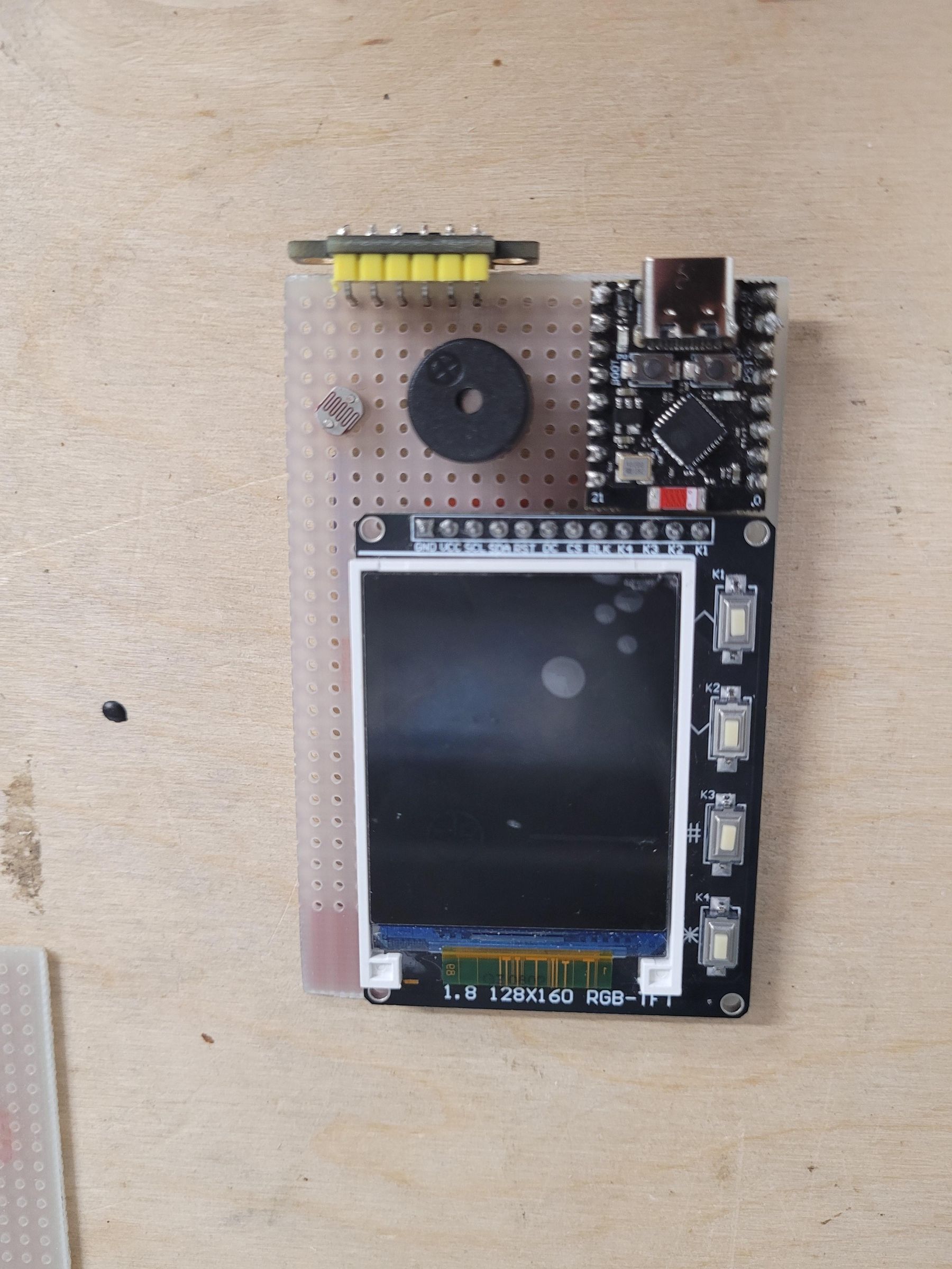
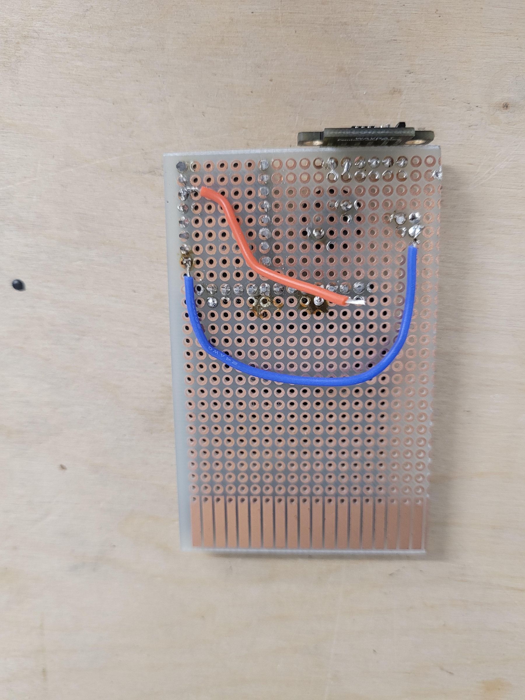
- Lay all your components on the universal PCB to see how they would fit and mark the dimensions (picture 1)
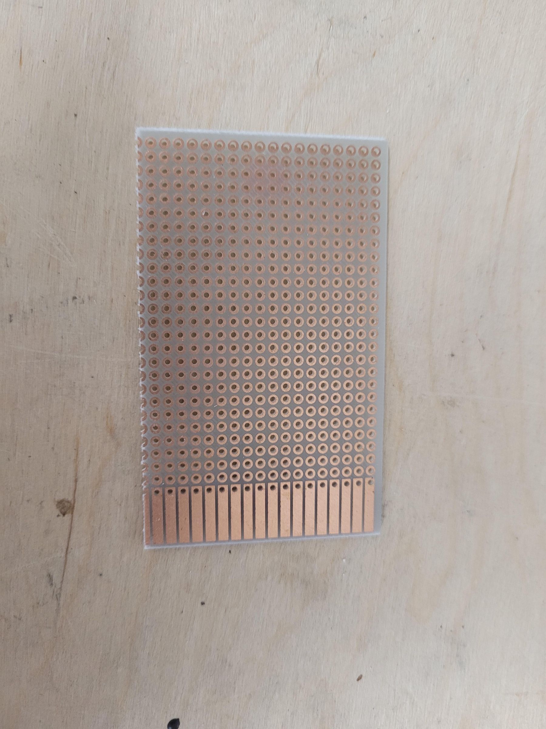
- Cut the universal PCB to its size so all the components would fit (Picture 2)
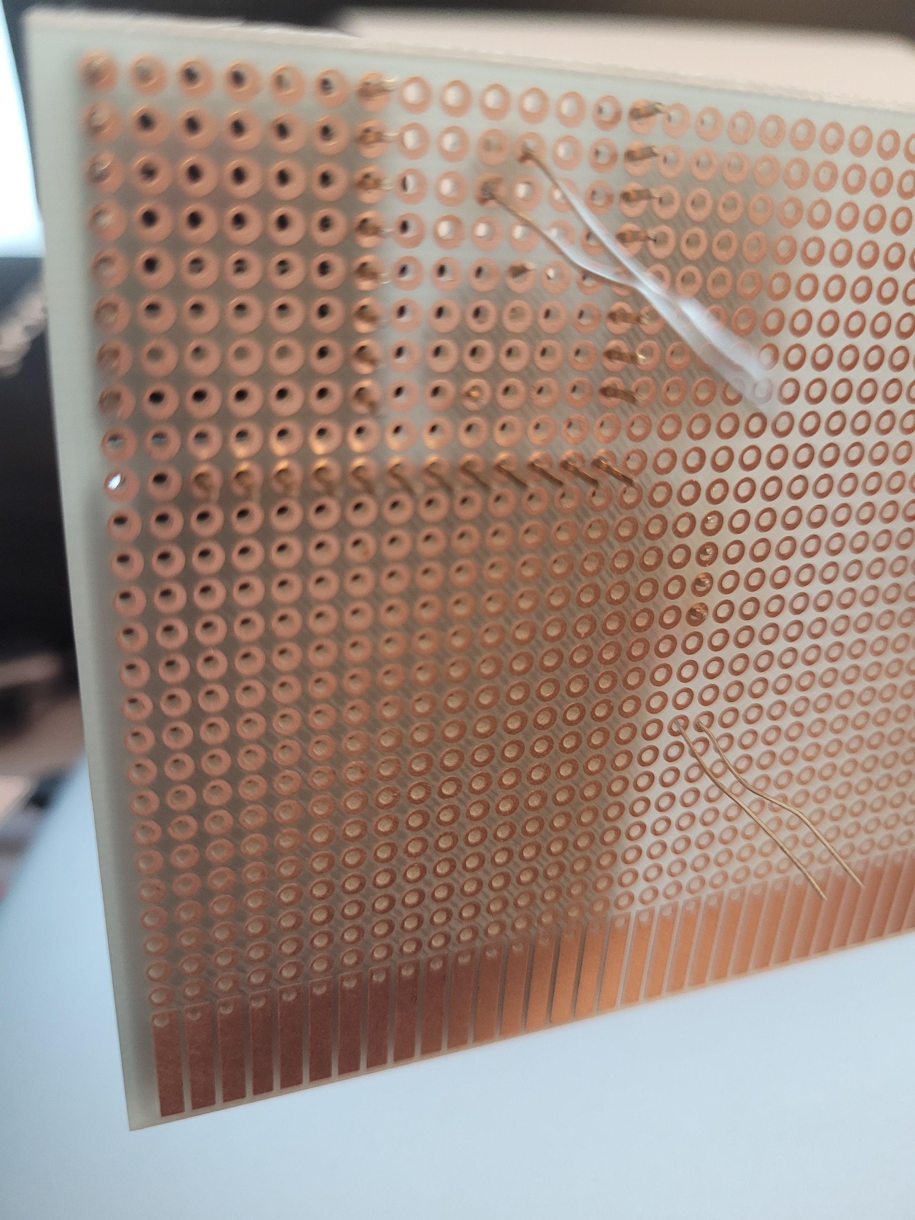
- Put the components legs thought the holes on the PCB and bend then so they wont fall out when soldering (Picture 3)
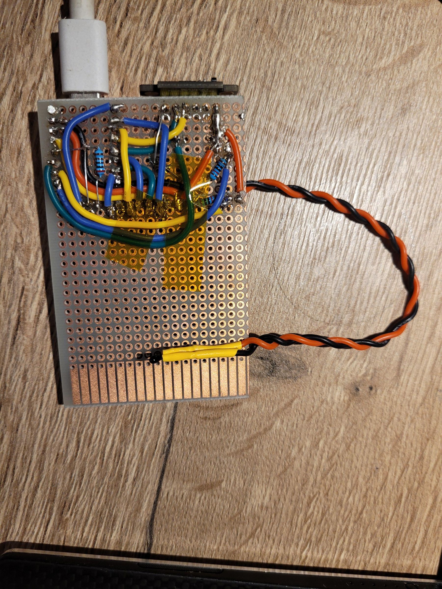
- Start soldering all the components one by one and the jumper wires (Picture 4)
- Finish soldering all the components and wires (Picture 5)
- Check that you wired all the connection correctly according to the wiring diagram specially ground and VCC so you don't accidently destroy some components
- Flash your ESP32-C3 supermini with the code from step 2
Test and Future Upgrades
Now you can plug it into power and see if it all works!
For upgrades you could hot glue a power bank to the back of the PCB so it can work without any external battery. It is also possible to add other I2C sensors such as gyroscope or accelerometer. In the future I could add a micro SD card reader for storing long data logs or even images. This card can be powered with any USB type C source, you can even plug it into your phone for power so it is portable and can be used everywhere (if you carry your phone and cable). Thank you for reading my instructable.