ESP32 SCOUT-E Robot (WALL-E Style)
by djanbjar in Circuits > Robots
1930 Views, 12 Favorites, 0 Comments
ESP32 SCOUT-E Robot (WALL-E Style)
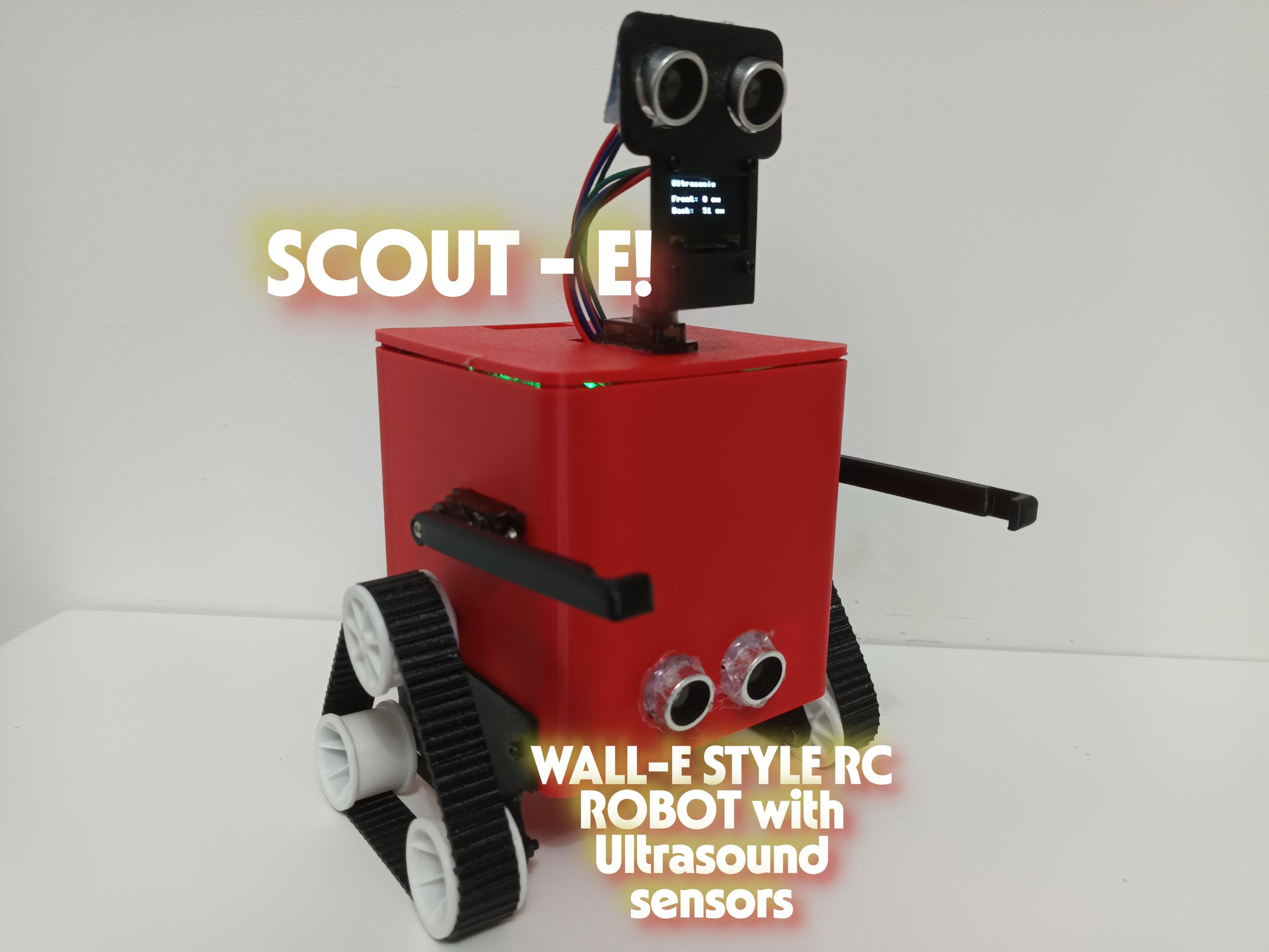
This project is a small autonomous robot built around an ESP32, ultrasonic sensors, motors, and an OLED display. It’s designed to detect obstacles, react to its surroundings, and show live information on the screen. The goal was to create a compact robot that feels a bit like a character—simple on the outside, but full of clever electronics inside. Check out the image above and this video link, to see the robot in its full glorious form.
I’m Diyan, 14, and I have lead this project from design to product, to bring it to life as a functional, moving, interactive robot, inspired by the cute character WALL-E from the Disney movie. I have my friend Geetank, who is also 14, as a second lead in the project, who had the original concept for this fun, engaging and innovative project.
We built this robot because we love making things that move, sense, and interact with the world. Being in the same class and school, together, we’ve been passionate about electronics for years, always experimenting with microcontrollers, sensors, and whatever parts we can get my hands on. This hands-on experience helped us understand how components work together and sparked our curiosity to learn more. We started from the bottom with the classic Arduino kit, and worked our way up from here with dedication, inspiration and curiosity! SCOUT‑E became the perfect way to bring all of that together into one project.
The build combines both the mechanical side (chassis, mounting, layout) and the electronics side (ESP32 programming, I²C OLED, ultrasonic distance sensing, power regulation). We wanted to create something that not only works, but also teaches us more about wiring, coding, and designing real hardware. This robot is the result of that curiosity—something practical, fun, and full of learning along the way, as well as countless hours, all-nighters and 5 months of work.
What you’ll learn from doing this project:
- Wiring and PCB Basics
- Micropython
- Parametric 3D Printing
- Mechanical Assemblies
In this guide, we aim to provide you with everything you need for this build, as well as the tools and information to build it further!
Supplies
️ Tools
These are the tools you’ll need. Some depend on which build method you choose.
Essential for all builds
- Soldering iron + solder
- Wire cutters/strippers
- Small screwdrivers (Phillips + flat)
- Tweezers (very helpful for small parts)
- Small pliers
- Multimeter (continuity + voltage testing)
- USB cable for programming the ESP32
- Computer for flashing firmware
- 3D printer (for the enclosure)
- PLA Filament (main body)
- TPU 95A Filament (For flexible easy print tracks)
- Hot glue gun or double‑sided tape (for mounting parts)
- 4 x 2 circular magnets * 6 (for making lid removable)
- Machine Screws
- CARTLOADS OF PATIENCE (I didn't realise until later!)
For the main electronics, there are 3 methods that can be done. I tried all three, and found that A worked perfectly first try:
A)If using the custom PCB
- Solder paste
- Flux pen (optional but recommended)
- Hot plate or hot‑air station for SMT reflow
- Fine tweezers for placing SMD parts
- Soldering iron for through‑hole connectors
- Standoffs or screws for mounting the PCB
B)If using perfboard
- Perfboard cutter or small saw
- Extra hookup wire for bridging connections
- Pin headers (for mounting modules)
- Patience — lots of it
C)If doing pin‑to‑pin wiring (no board)
- Heat‑shrink tubing or electrical tape
- Extra flexible silicone wire
- Hot glue for strain relief
- Optional: small breadboard for layout planning
Materials & Electronic Components
Core Electronics (same for all build methods)
- ESP32 Dev Board (only if not using Custom PCB)
- HC‑SR04 ultrasonic sensor * 2
- MG90S Servo * 3 (two for arms, one for head
- 0.96" I²C OLED display (SSD1306)
- LM2596 buck converter (to step battery voltage down to 5 V)
- L298N Motor Driver
- N20 Motor * 2
- 7.4 V battery pack ~2000 mAh Preferably from a reputable seller (Amazon, hobby stores)
- On/off switch
Wiring & Hardware
For all builds
- Jumper wires
- JST connectors
- Crimping tool (not necessarily needed if using pre crimped wires)
- Small‑gauge hookup wire
- Zip ties or cable management clips
- Heat‑shrink tubing
A)If using the custom PCB
- SMD Components (BOM is attached, simply upload to LCSC.com and buy, includes the ESP32 module)
- Custom PCB
B)If using perfboard
- Perfboard sheet
- Extra pin headers
- Extra hookup wire
- Optional: copper tape for ground rails
C)If doing pin‑to‑pin wiring
- Flexible silicone wire
- Hot glue for strain relief
Printing
The first step is to 3D‑print all the required parts for the build. You’ll need to print the following components, that I designed in Fusion 360:
- Body
- Lid
- Head
- Arm * 2
- Side wheel mounts (Left and right)
- Driver wheels * 2
- Driven wheels * 4
- TPU Tracks * 2
- Motor mount * 2
Print Settings
All parts were printed using the default Bambu Studio profiles, with no special tuning required.
- PLA parts (body, wheels, mounts, head, lid): Default Bambu PLA profile (0.2 mm layer height, standard walls & infill)
- TPU tracks: Default Bambu TPU 95A profile (slow speed automatically applied)
These defaults work perfectly because the tolerances on these parts are fairly forgiving, so they should print well on most consumer 3D printers without any special adjustments. All STL files are included in the project attachments. If there are any problems at all with them, please let me know, and I will attempt to fix them as quickly as possible.
If your printer under‑extrudes TPU, reduce print speed slightly; the default Bambu Studio TPU profile worked well for me.
Electronics
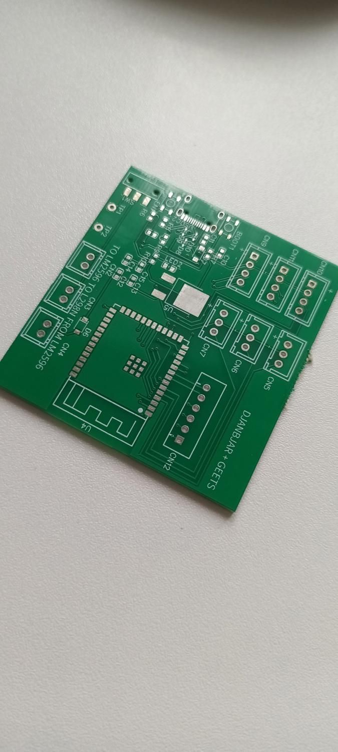
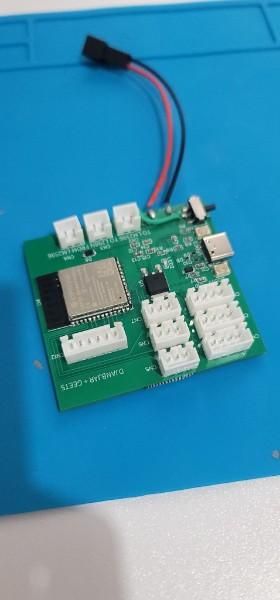
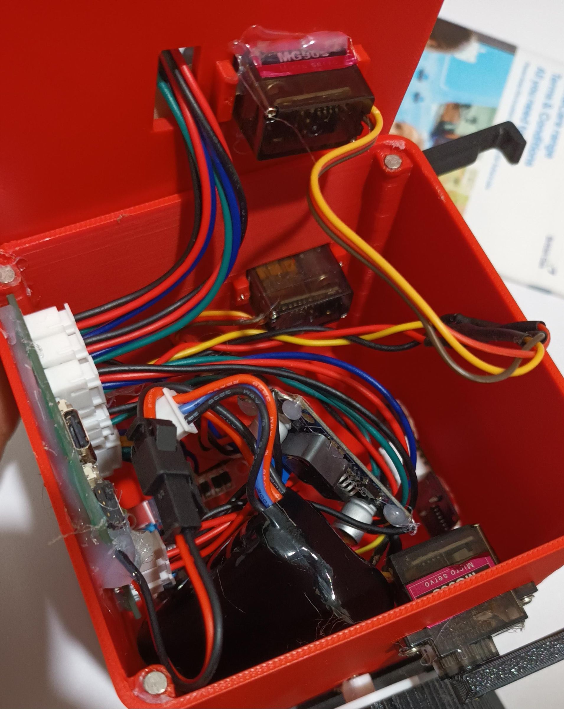
For all of these options, do not worry if it looks a bit messy. I attached a photo of my PCB build, which was meant to be the cleanest, but it still looks pretty messy. The purpose of the case is to hide that messiness.
🔵 Custom PCB (recommended — most reliable and cleanest)
If you’re using the custom PCB, you can order it directly from this EasyEDA project
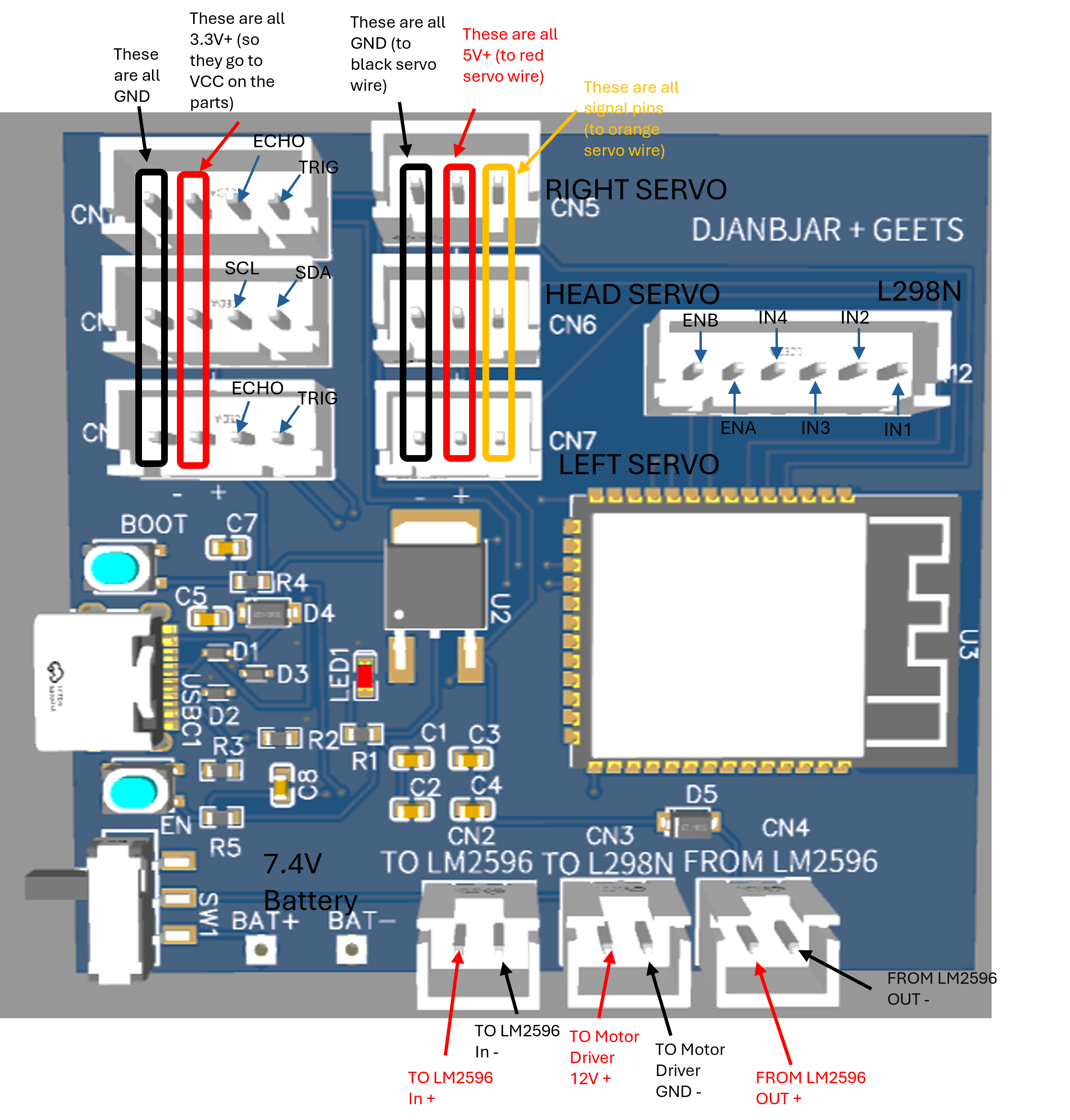
Throughout this project, I will be mainly providing support and advice for the Custom PCB option, as it is the most reliable and easiest option, although I will also be providing direct support and advice for the other two options if I am directly contacted about it.
Open the PCB file (not the schematic), then go to Fabrication to download:
- Gerber files (board manufacturing)
- BOM (parts list)
- Pick‑and‑place file (for automated assembly)
If you want full assembly, upload these files to JLCPCB during checkout. One tip: don’t include the JST connectors in the assembly — through‑hole parts add a lot to the cost. It’s far cheaper to solder the JST‑XH connectors yourself, so if you want to do these yourself, simply download the BOM, open it in excel, and remove the lines that say JST-XH Manually, as these are the only expensive connectors.
I was working on a tight budget during prototyping, so I ordered only the bare PCB from JLCPCB and bought the components separately from LCSC using the BOM. This brought the cost down significantly, and wasn't too difficult.
Important: During the purchase process, ensure the following things:
- The PCB is ordered correctly (with the BOM and Pick-and-place if necessary)
- If you are assembling yourself, ensure that every part you want to buy in the BOM corresponds to an LCSC part that is in stock, in order to avoid delays and further issues.
Note: On the PCB, there are 2 little pads, TP1 and TP2. These are for wiring the Battery Female connectors to (TP1 is +, TP2 is Ground.) When adding the battery JST (not XH), make sure you know which wire is positive and which wire is negative, as some JST wires flip these round.
To assemble the board yourself:
- Apply solder paste to the SMD pads
- Place the components according to the schematic from the link above
- Reflow using a hot plate or hot‑air station
- Solder the through‑hole parts (JST connectors, usb-c legs) with a normal iron
This method gives the cleanest layout and the most reliable electrical connections.
Test the board through USB-C and then through the battery 7.4v with the LM2596 plugged in (otherwise the PCB won't receive power, to ensure proper functioning. A tip for when testing: be prepared for anything. When plugging in the battery, stay ready to unplug it quickly if the PCB LED doesn't light, as it is often a sign of a short-circuit.
🟩 Perfboard Build (works, but fiddly)
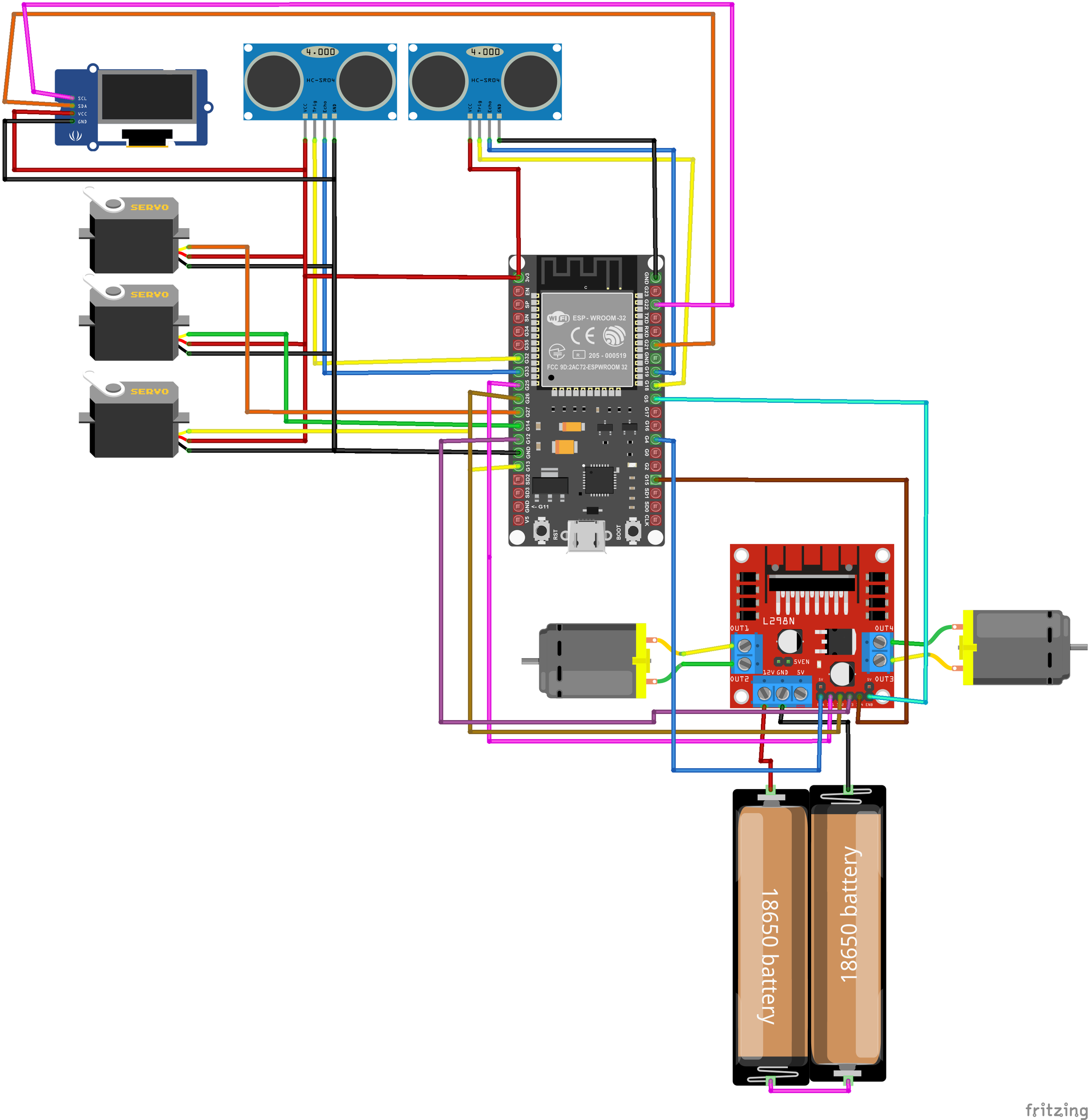
If you’re using perfboard, everything is soldered with a standard iron. For the connections, please refer to the Fritzing diagram in the attached images above. ALSO, IN YOUR CODE, YOU MUST MAKE SURE THAT THE CONNECTIONS ON YOUR BOARD MATCHES THE PIN NUMBERS WITHIN THE CODE. This is extremely important to ensure correct functionality. Different dev boards have different pinouts, which is why I couldn't provide a universal code... Also, the Fritzing diagram above is just to reference how the layout should be. When replicating this, you shouldn't directly copy what the diagram says, as different dev boards have different pinouts. Search up on Google for the pinout on your specific Dev board, to ensure that you're not clashing with system pins (e.g the EN pin is used for resetting the board).
- Place the modules (ESP32 dev board, OLED, HC‑SR04, buck converter) on the board
- Add pin headers so modules can be removed or replaced
- Use short pieces of wire to connect everything following the schematic
- Add JST connectors for the battery, sensors, and servos
This method is good for prototyping, but routing wires neatly takes patience. Messy wiring or poor solder joints can cause shorts, so work slowly and check each connection.
🟧 Pin‑to‑Pin Wiring (only if you have no other option)
This is the most difficult and fragile method. It works, but it’s easy to end up with a messy “rat’s nest.” For the connections, please refer to the Fritzing diagram in the attached images above. ALSO, IN YOUR CODE, YOU MUST MAKE SURE THAT THE CONNECTIONS ON YOUR BOARD MATCHES THE PIN NUMBERS WITHIN THE CODE. This is extremely important to ensure correct functionality. Also, the Fritzing diagram above is just to reference how the layout should be. When replicating this, you shouldn't directly copy what the diagram says, as different dev boards have different pinouts. Search up on Google for the pinout on your specific Dev board, to ensure that you're not clashing with system pins (e.g the EN pin is used for resetting the board).
- Remove jumper pins from modules — they get in the way
- Solder wires directly to pads or pins
- Use heat‑shrink or hot glue for strain relief
- Double‑check every connection to avoid accidental bridging
You don’t need JST connectors for this method, but every wire must be secure and insulated. This approach is lightweight and cheap, but the least durable.
Assembly
This is where everything finally comes together. Work slowly, check each step as you go, and your robot will assemble beautifully.
1. Install the Motor Mounts
- Attach each motor mount to the lower sides of the robot body using M2.5 × 12 mm screws.
- The slotted (adjustable) hole must face the rear of the robot — this is your track tensioner.
2. Install the N20 Motors
- Place each N20 motor into the raised motor platform.
- The motors should already have two wires soldered on.
- Position the extra motor clamp over the motor so its hole aligns with the hole in the platform.
- Insert an M3 × 20 mm screw through the clamp and secure it with a washer and nut on the inside.
3. Install the Servos
- Each servo should already be converted to JST‑XH wiring.
- Center each servo to 90° before installation (send a 1500 µs pulse or use a servo tester).
- Insert the servos from the outside of the body inward.
- Secure them using the small screws included with the servo, or use hot glue
- Make sure the servo shafts face the correct direction (side servos forward, head servo upward).
- Also, attach the arms onto the sides, so that the arms face forwards.
4. Install the Head Components
- Mount the OLED display using four M2 × 6 mm screws + nuts.
- Insert the HC‑SR04 ultrasonic sensor into the two pairs of holes (one pair in the head, one in the body).
- Secure it with a small amount of hot glue.
5. Install the Wheels
- Slide the driver wheel onto the N20 motor shaft.
- Install the driven wheels using this order (outside → inside): M3 × 20 screw → washer → wheel → nut → washer → chassis hole → washer → nut
- The wheel must spin freely while the screw remains tight.
6. Install the Tracks
- Slide the tracks over the driver and driven wheels.
- Tighten the tensioner until the track has 2–3 mm of vertical play.
- Too tight = friction; too loose = derailing.
7. Install the Magnets
- Insert the 4×2 mm magnets into the lid and body.
- Check polarity before gluing — all magnets must attract.
- If the fit is tight, warm the plastic slightly with a hot glue gun and press the magnet in.
Wiring Everything
8. Prepare the JST‑XH Connectors
Attach JST‑XH female connectors to:
- OLED
- HC‑SR04
- All servos
- L298N control pins (ENA, IN1, IN2, IN3, IN4, ENB)
This makes repairs and replacements much easier.
9. Connect the Motors to the L298N
- Screw the two motor wires into Motor OUT1 and Motor OUT2.
- If a motor spins the wrong direction later, simply swap the wires.
10. Connect Power to the L298N
- Add a JST‑XH connector to two wires and screw them into +12V and GND on the L298N.
- The JST end plugs into the L298N port on the PCB.
11. Connect the LM2596
- Add JST connectors to both sides of the LM2596.
- Before connecting it to the PCB, adjust the LM2596 output to exactly 5.0 V using a multimeter, and the blue pot. NEVER plug the LM2596 into the PCB until you’ve confirmed the output voltage with a multimeter
- Plug:
- IN → “TO LM2596” on the PCB
- OUT → “FROM LM2596” on the PCB
- Secure the LM2596 inside the chassis with hot glue or double‑sided tape.
12. Mount the PCB
- Hot glue the PCB to the rear wall of the body.
- Ensure the USB‑C port, switch, and buttons align with the openings in the lid.
13. Final Connections
- Plug in the OLED and HC‑SR04 using the 4‑pin JST connectors.
- Plug in the three servos using the 3‑pin JST connectors.
- Plug in the 6‑pin JST for the L298N — follow the diagram exactly to avoid reversed directions.
- Double‑check all polarity markings before powering on.
Software
This is a remote‑controlled robot, controllable over Bluetooth, so we’re going to need some software to bring it to life.
For this project, I chose MicroPython because:
- It’s easy to write and read
- It has a rich ecosystem of libraries
- It’s popular and well‑documented, which makes this robot highly expandable
Same hardware, new software — you can completely change how the robot behaves just by flashing different code.
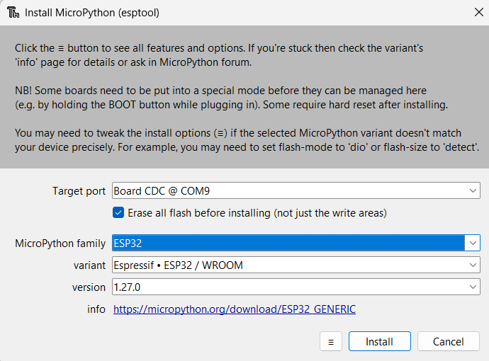
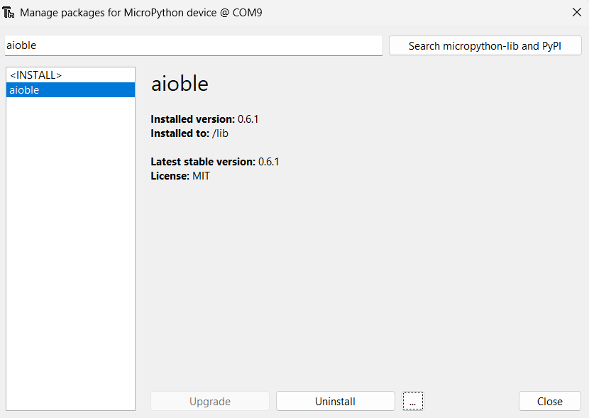
You can refer to the images attached for help with flashing micropython and installing aioble.
Before you begin, please ensure that the board is being powered over USB-C, not over the battery, to avoid damaging the board at this stage
1. First boot and setup
- Install Thonny
- Download and install Thonny IDE (just search “Thonny Python IDE”).
- Open Thonny once it’s installed.
- Connect the robot board
- Plug the robot into your computer using a USB‑C cable.
- Turn the robot on if there’s a power switch.
- Select the correct interpreter in Thonny
- In Thonny, go to: Tools → Options → Interpreter
- Under “Interpreter”, choose: MicroPython (ESP32)
- Under “Port”, select the COM port / device that appears when you plug in the board.
2. Flashing MicroPython firmware to the ESP32
If your board doesn’t already have MicroPython installed, you’ll need to flash it once.
- Open the firmware dialog
- In Thonny, go to: Tools → Options → Interpreter
- Click “Install or update MicroPython” (or similar button at the bottom).
- Choose the board and firmware
- Board: ESP32
- Firmware: Use the espressif firmware if you can find it
- Let Thonny download the latest stable MicroPython firmware automatically.
- Put the board into bootloader mode (if needed)
- If Thonny asks you to, press and hold the BOOT button on the board while it connects.
- Some boards don’t need this; if it flashes successfully, you’re good.
- Flash the firmware
- Click Install and wait until Thonny reports success.
- When it’s done, the board will reboot into MicroPython.
- Test the REPL
- In Thonny’s bottom shell, you should see something like: MicroPython vX.X on ESP32
- Type:
- print("Hello")
- and press Enter.
- If it prints back, your firmware is working.
3. Uploading the robot code
Now that MicroPython is running, we can upload the code that controls the robot.
- Create the main script and packages
- In the Thonny editor, upload the main.py file attached, as well as the other driver files (ssd1306.py, servo_library.py, hcsr04.py), by opening each python file attached in Thonny, then going through each one and clicking Ctrl (or CMD)+ Shift + S, or Save As, and then select Micropython Device to save the file to the ESP32.
- If you are not doing the Custom PCB method, as I've mentioned before, PLEASE MAKE SURE THAT THE PIN NUMBERS ON THE DEV BOARD MATCH WITH THE PIN NUMBERS IN THE BOARD TO ENSURE CORRECT FUNCTIONALITY. Different dev boards have different pinouts, which is why I couldn't provide a universal code...
- Also, there is another package that must be installed using Thonny's inbuilt package manager, called aioble, and it will be used for interfacing the robot with bluetooth and the phone controller. For this, simply go to Tools, then Manage Packages, and then search up aioble, and then click install.
- Run the script
- In Thonny, click the green button to test the script, with everything connected correctly. If all is well, the robot should snap its arms and heads a bit, and something should show on the robot OLED. This servo position is the 90 degrees or neutral position, so you may want to correct the arm/head alignment.
- If there any problems, such as errors, or the OLED doesn't work etc, please refer to the troubleshooting section below👇, and if there's nothing there related to your issue, just drop me a comment or DM and I'll get back to you ASAP.
4. Connecting to Bluetooth
After getting the main script to run, we now need to connect to the bluetooth.
- Download the APK
- Download the APK HERE onto your android device (I'm working on a iOS and web app, so hang tight Apple users!). You may need to allow installation from unknown sources. On first run, it will ask for a few permissions. It only needs these to access the bluetooth device.
- Connect to bluetooth
- Now, you have the app, turn on the robot with the battery plugged in. The green light should turn on to indicate power, and now look at the android app. Click the scan button, and select the ESP-32 device from the dropdown menu. If the connection is successful, it should show you a gamepad.
5. Enjoy!
- Try all the buttons! The d-pad moves the motors, and there are buttons to move the arms and head. The robot may twitch or move slightly when first powered — this is normal as the servos initialize
TROUBLESHOOTING + FAQ
Now, if you've come to a point where a problem has arisen. But do not fear, as I am here! In this section, I shall quell your problems using the power of Q&A!
Q: I'm getting an ENODEV error in Thonny!!!
A: This refers to the I2C connection between the ESP32 and the OLED display, generally indicating towards incorrect wiring or pin numbers. First, have a look that the SDA and SCL pins are plugged into the corresponding ESP32 pin (use the pcb schematics for this). If that is alright, have a look and see for mis-soldered or loose connections, maybe even a short circuit.
Q: On Thonny, my device isn't showing when I plug it in.
A: This is generally a result of 2 different things. It could be the cable you are using is not a data cable, and is only used for charging, in which case, switch to a USB-C cable that supports charging. It could also be that the USB-C port on the actual board is faulty, maybe due to a mis-connection, in which case, have a look carefully at the board's USB-C - it may not be aligned properly, or floating pins, which may need a bit of resoldering.
Q: I'm getting a ticking/beeping sound from my servos!!
A: This is generally result of servo strain, i.e. the servo is trying to move to a position, but it can't due to a restraint, so it keeps trying and gets very frustrated. In this situation, it may be because of the tightness of the arms or the head mount onto the servo, which can be simply fixed by loosening the screws, and making sure the screw isn't too tight.
Q: My motors spin in a funny way!
A: This is not exactly a hard problem to fix. As long as they are running, this is just the result of the motor wires being flipped, and can be easily fixed by either manually flipping the wires on the L298N or by flipping the pins IN1/2 or IN3/4 around in lines 99-104 of main.py.
Q: I burnt a PCB trace, what do I do???
A: I managed to burn a lot of pcb traces when prototyping this project, so do not worry! Simple find the trace, and assess the damage (and also find the cause of it and fix that first). Then, use a piece of wire to bridge the connection between two intact points that the trace originally connected, and add a bit of hot glue to secore it in place, and voila! Good as new...
Conclusion
By this point, you should now have your very own SCOUT‑E — a brilliant, cute, personal little robot companion you built yourself. That’s no small achievement, and you should be proud of it.
If you run into any problems at all (seriously, nothing is too big or too small), just drop a comment. Hearing what people struggle with helps us improve future versions and make the project even more accessible.
As for what comes next, we already have a few exciting upgrades planned:
- A programmable mode — similar to those children’s coding games — where you can create simple sequences like “move forward 3 steps” or “turn left,” giving SCOUT‑E a fun educational twist.
- Autonomous driving, using the two ultrasonic servos to scan the environment and let the ESP32 decide where to go.
- Animated facial expressions and other personality features on the OLED display, so SCOUT‑E feels even more friendly and pet‑like.
This project has been a long journey of ups and downs, full of challenges and breakthroughs. We put our heart, soul and tireless commitment into this project, and went above and beyond, because we wanted to create something others could enjoy building too. Seeing people make their own versions is the best reward we could ask for.
If you’d like to show support, anything helps — a favourite, a share, an “I Made It!”, or even just a comment. Every bit of feedback fuels the next project and keeps this whole adventure going. If anything is vague or difficult to understand, please let us know ASAP so we can fix it.
We’re only 14, and still right at the beginning of our journey in electronics — but we hope this project shows that you don’t need to wait until you’re “older” to build something real. SCOUT‑E pushed us in ways we didn’t expect, and every challenge, late night, and tiny breakthrough taught us something new. If this robot inspires even one other young maker to try building something of their own, then all the effort was worth it.
Thanks for building SCOUT‑E with us. 👍