ESP32 WiFi Package Sorting Robot With Live Camera
by Vazha03 in Circuits > Robots
2190 Views, 22 Favorites, 0 Comments
ESP32 WiFi Package Sorting Robot With Live Camera
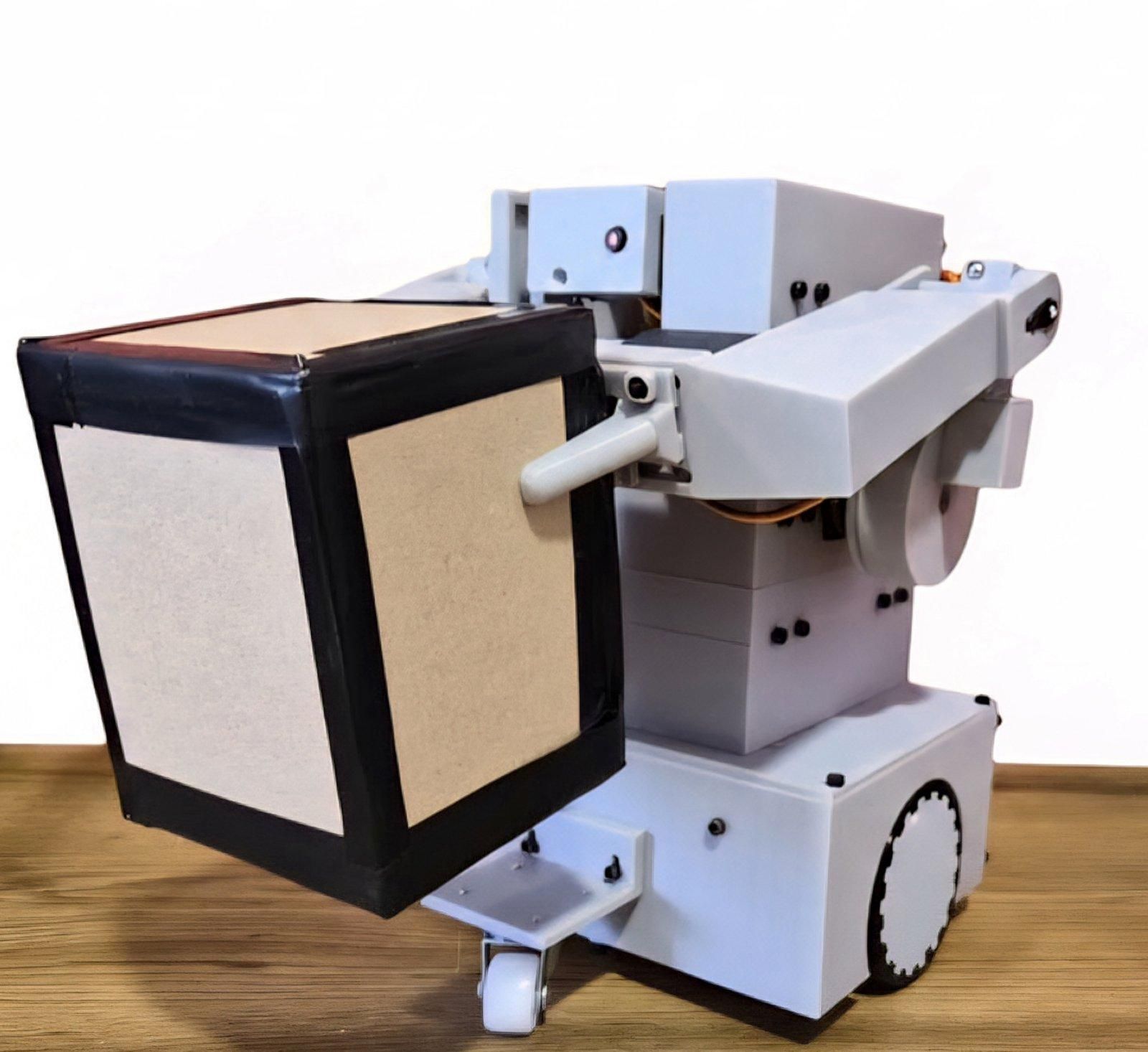
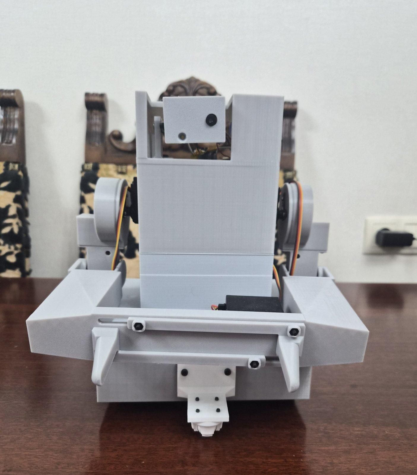
Welcome! In this project, I'll show you how I built a WiFi-controlled package sorting robot using an ESP32, a robotic arm, and an ESP32-CAM for live video streaming.
The robot is designed to remotely pick up and transport small packages while the operator controls it through the Blynk mobile app. The live camera feed allows the robot to be driven from a distance, making it easier to place packages accurately without directly seeing the robot.
The robot features:
- A robotic arm capable of picking up and placing packages.
- WiFi control using the Blynk app.
- Live video streaming with an ESP32-CAM.
- An OLED display for robot status information.
- Battery-powered operation for completely wireless use.
I built this project to explore how warehouse robots work and to create a compact prototype that combines robotics, wireless communication, and embedded programming into a single system. While this robot is a scaled-down model, it demonstrates many of the same ideas used in automated material-handling systems.
If you'd like to build your own WiFi robotic arm or learn more about ESP32-based robots, this guide will walk you through every step of the process.
Supplies
Electronics
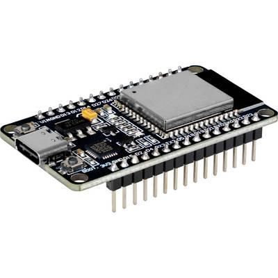
- 1 × ESP32 Board
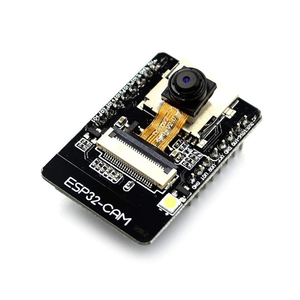
- 1 × ESP32-CAM
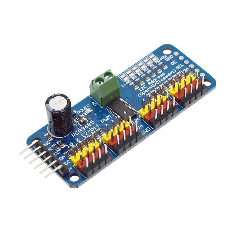
- 1 × PCA9685 16-Channel Servo Driver
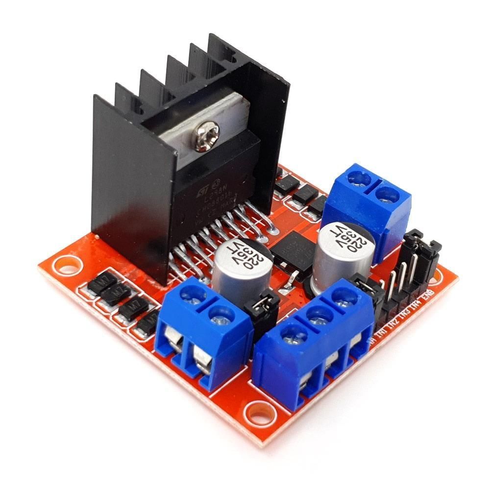
- 1 × L298N Motor Driver
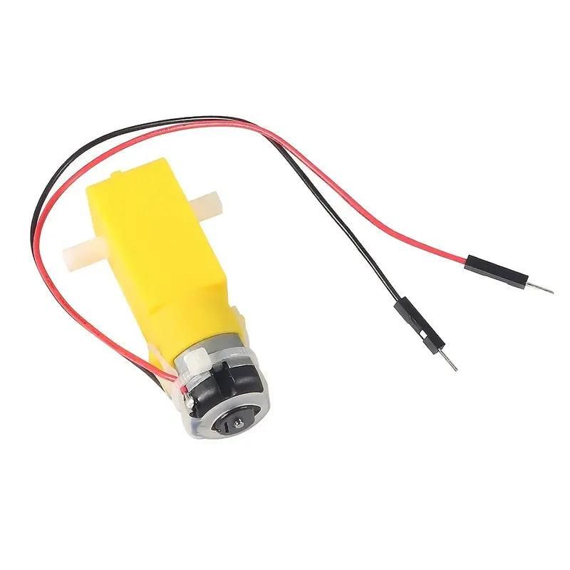
- 2 × DC Gear Motors
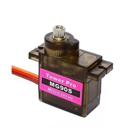
- 3 × MG90S Servo Motors
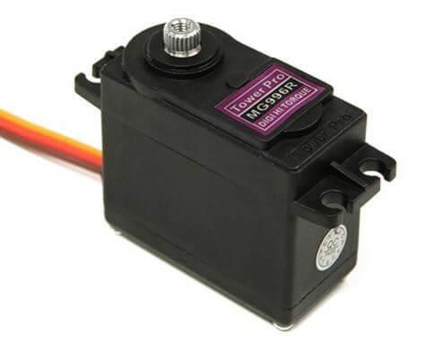
- 3 × MG996R Servo Motors
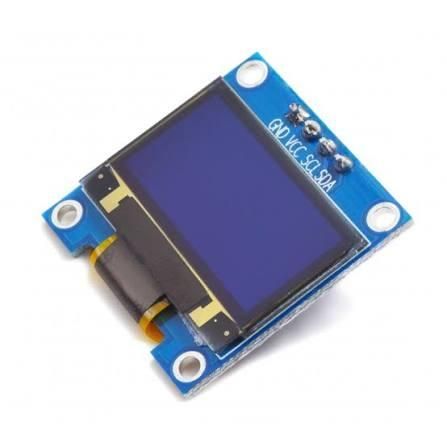
- 1 × 0.96" SSD1306 I2C OLED Display
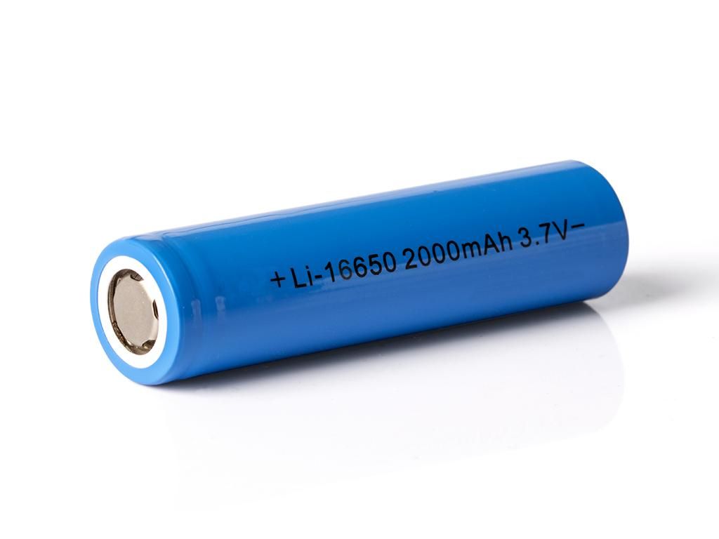
- 2 × Li-ion Battery (2000mAh each)
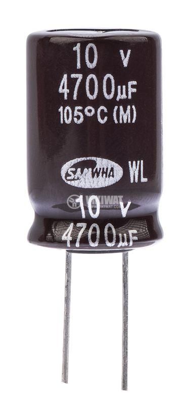
- 1 × 4700uf Capacitor
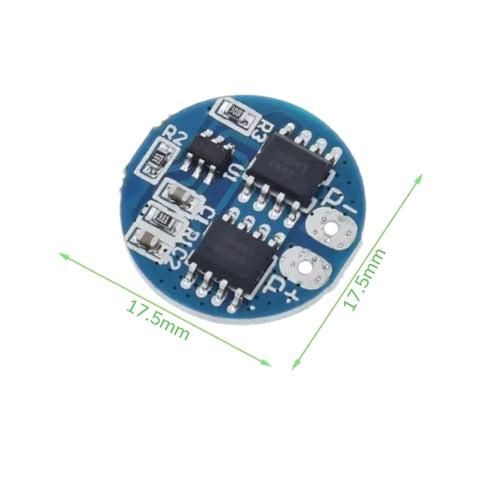
- 1 × 2S BMS
- 1 × Power Switch
- Jumper wires
- Male/Female header pins
3D Printed Parts
- Robot chassis
- Robotic arm base
- Robotic arm links
- Gripper
- Camera mount
- Electronics mounting brackets
All of these parts are included in the downloadable STL files.
Hardware
- M3 screws (various lengths)
- M3 nuts
- Servo screws
- Zip ties (optional)
Software
- Arduino IDE
- Blynk IoT
- Blender (for designing robot)
- ESP32 Board Package
- Adafruit PWM Servo Driver Library
- Adafruit GFX Library
- Adafruit SSD1306 Library
Tools
- 3D Printer
- Soldering Iron
- Solder
- Screwdrivers
- Wire Strippers
- Hot Glue Gun (optional)
3D Printing Parts
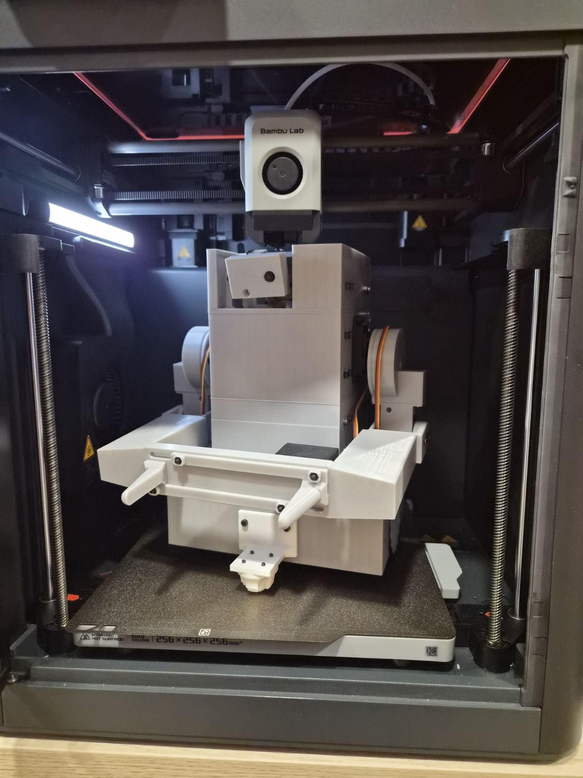
All of the robot's structural components were designed for 3D printing. Print each part before beginning assembly.
I printed the most parts using PLA. I used PETG for parts, which needs no be strong like the arm. I also used TPU for tires.
After printing, remove any supports and test-fit the parts before assembly.
Downloads
Building the Robot
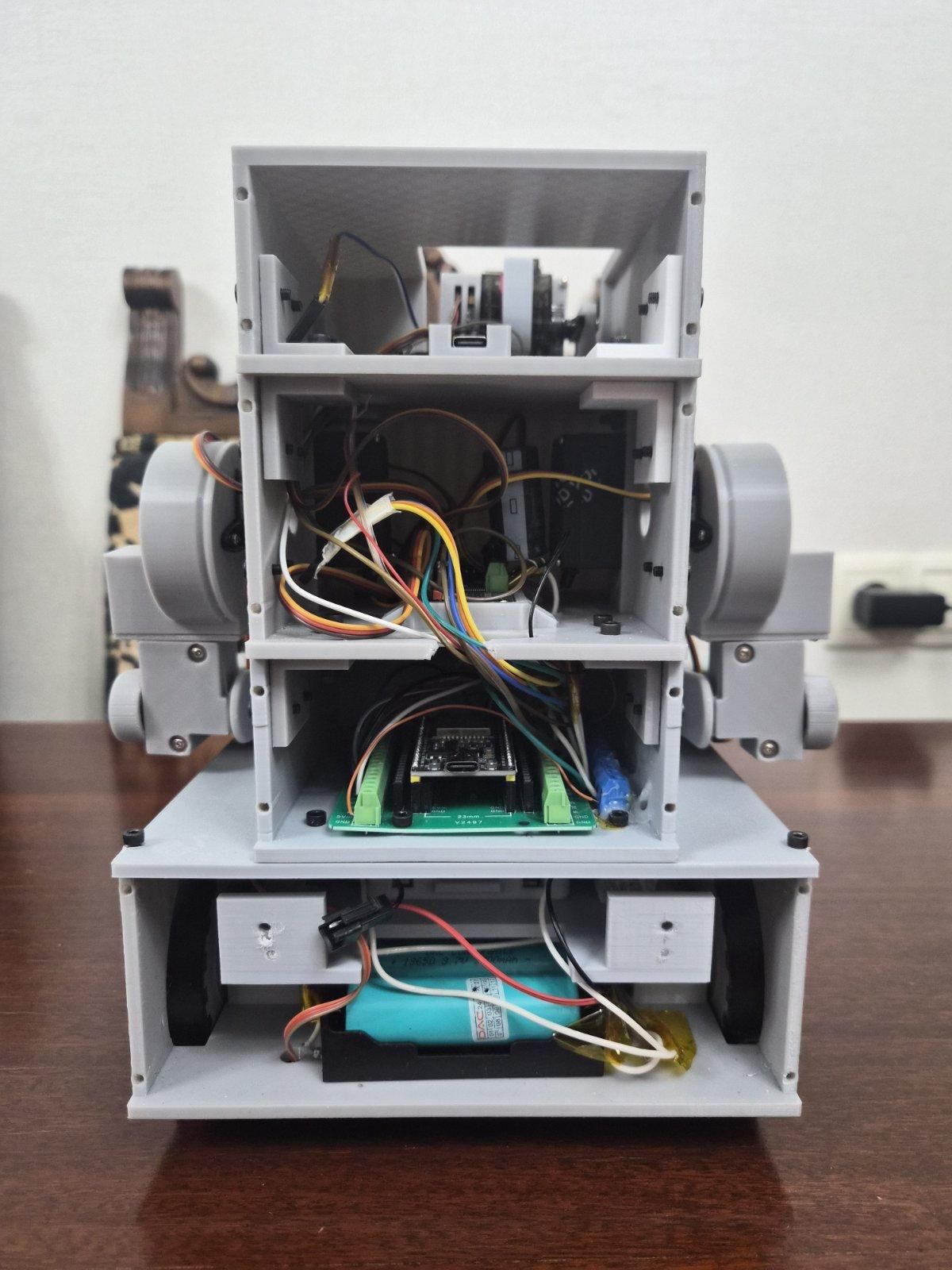
After printing all parts, start assembling the robot with components. The robot consists of 4 layers and you should build it following the order of the layers.
Layer 1
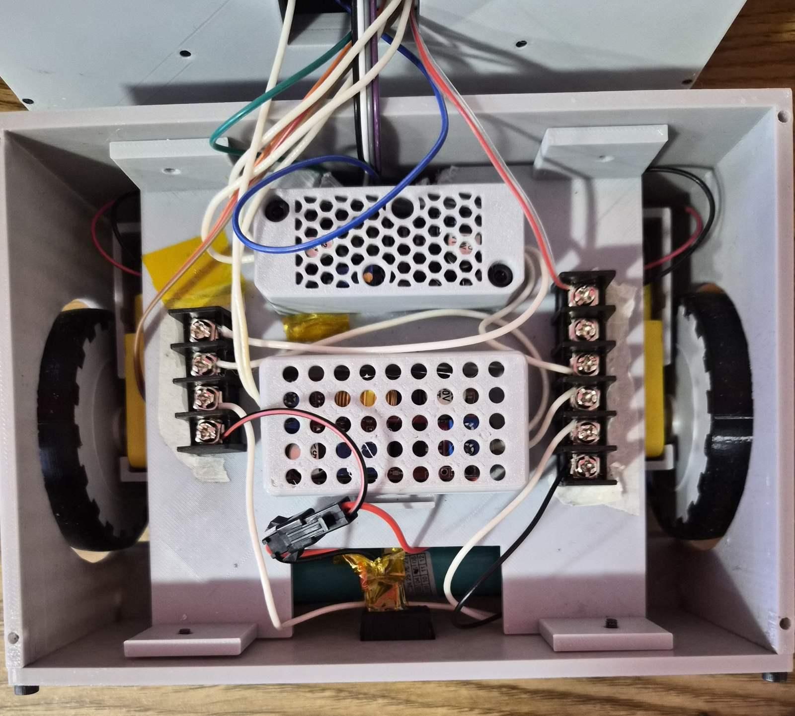
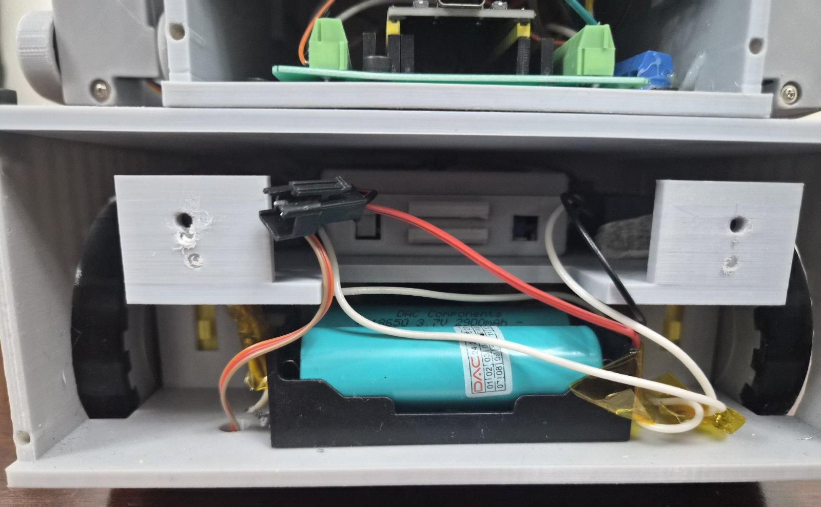
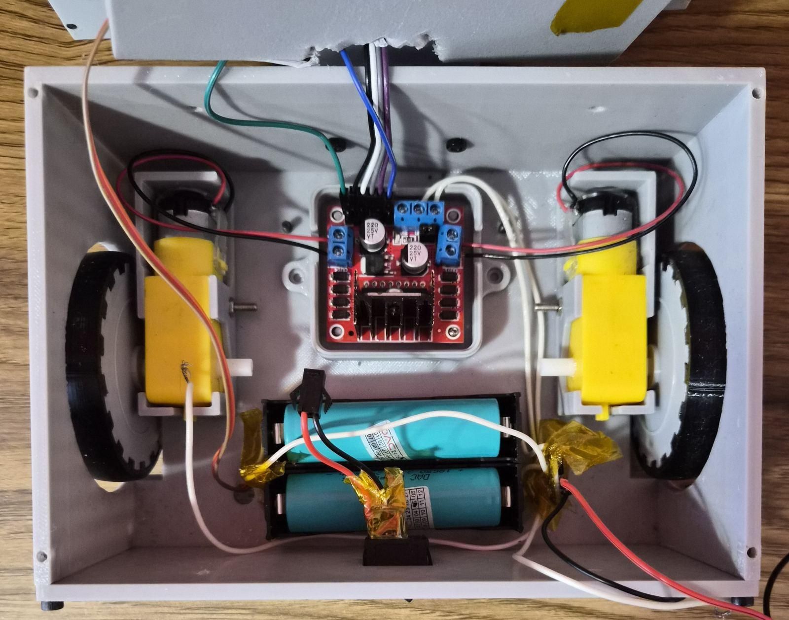
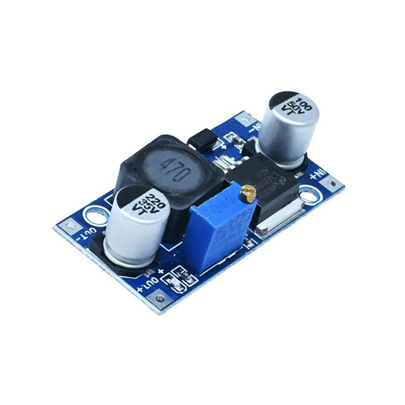
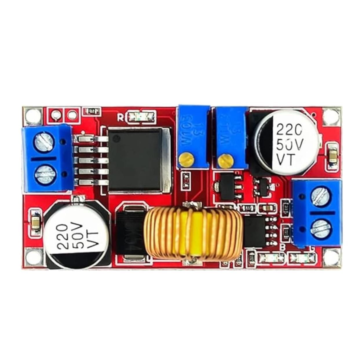
This layer consists of most components, because it must be the heaviest part of the robot, so the COM (center of mass) will be low. This will prevent robot from falling over easily. First start by soldering the two battery holders to the 2s bms. This connects to power positive rail and gnd rail. 3 components are connected to these rails: 5V buck converter (for esp32, oled screen, etc.), 6V buck converter (for servos only) and L298N driver( for two DC motors. Also a switch is connected between 2s bms and power rail, which turn on and off the robot. After electronics, you can attach the wheels to the motors and a 3d-printed caster wheel the robot.
Layer 2
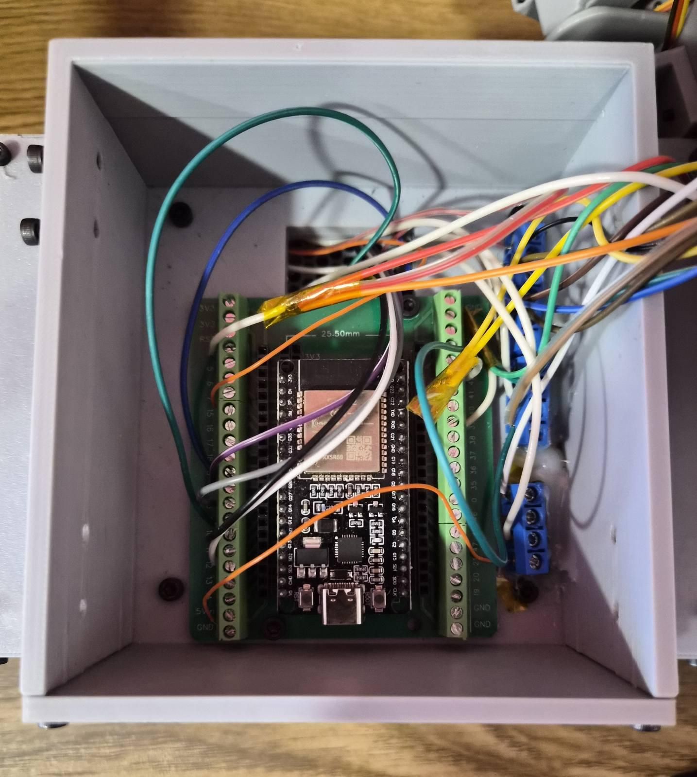
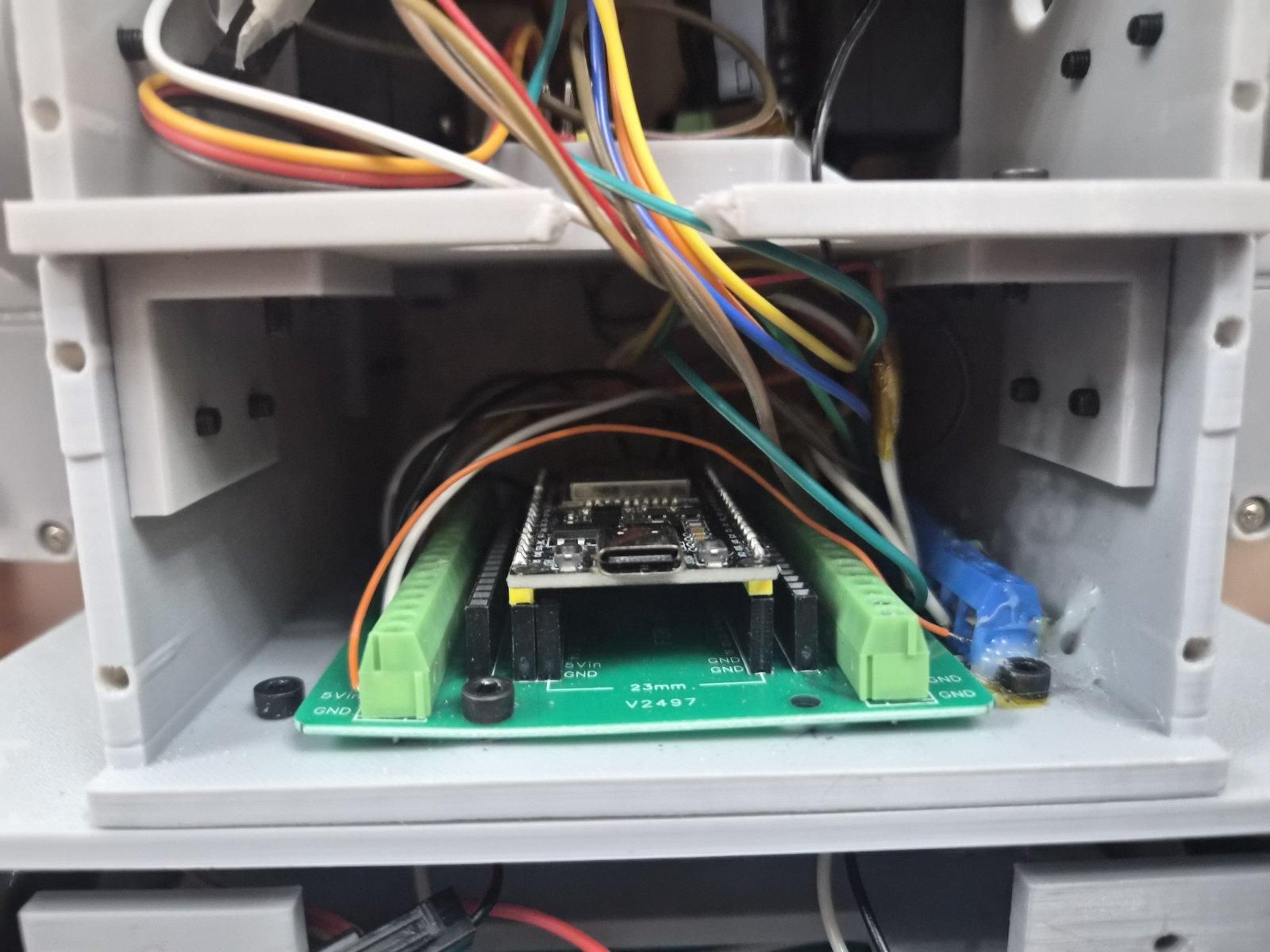
The 2nd layer consists only ESP32 (the brain board), 2nd gnd rail (which must be connected to the first gnd rail) and 5V rail. the ESP32 has an adapter, which makes connecting and disconnecting the wires easier. You can hot glue the rails to the 3d-printed chassis, so connecting the wires will be easier.
Layer 3
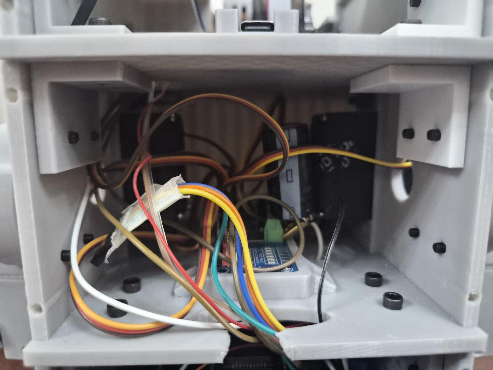
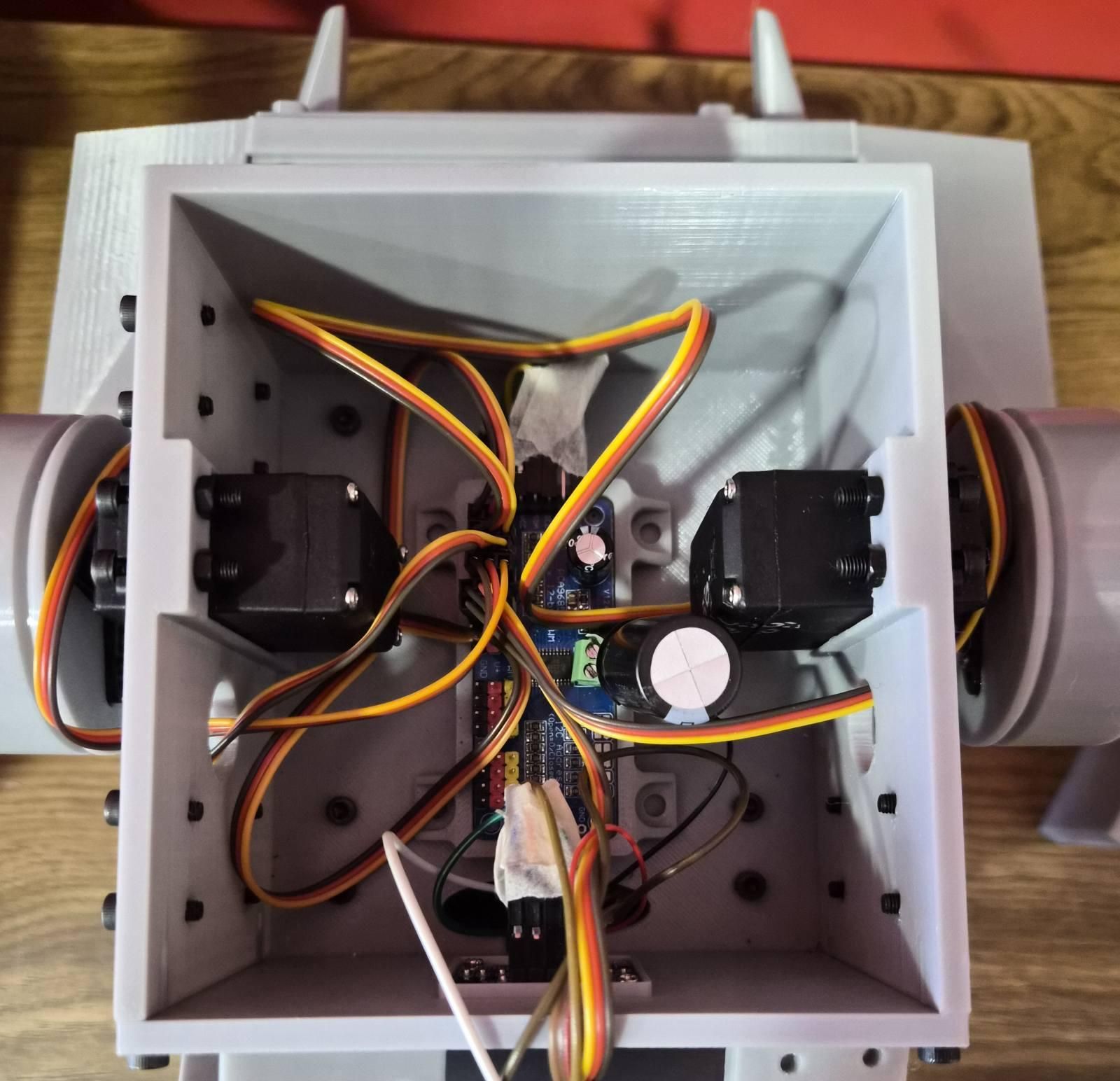
The 3rd layer consists of PCA9685 board (where all servo connections take place) and OLED screen (which is mounted on the removable plate on the main chassis of the 3rd layer). I attached a 4700uf Capacitor on the power terminals of PCA9685 board (to minimize the jittering of the servos).
Layer 4
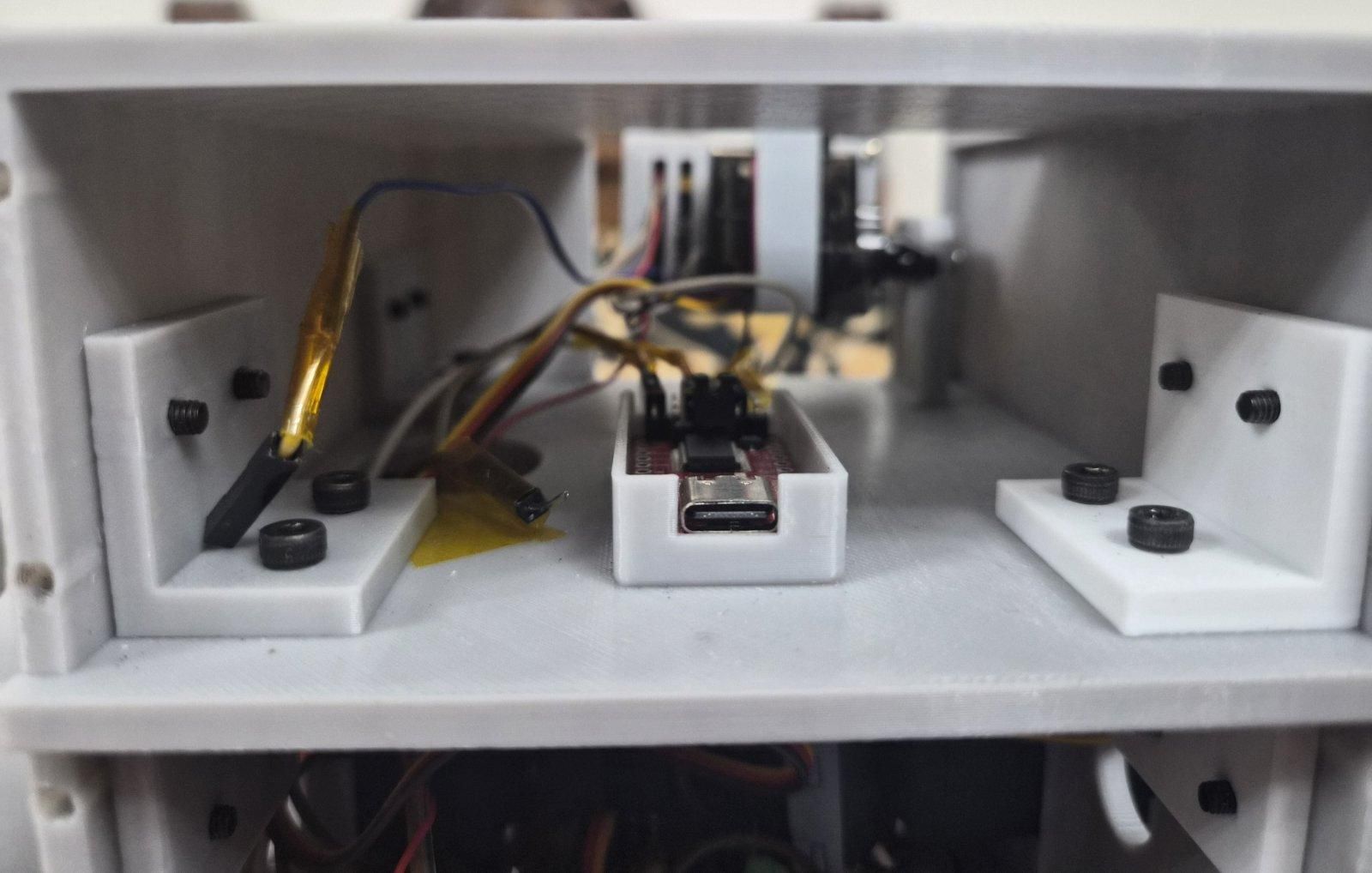
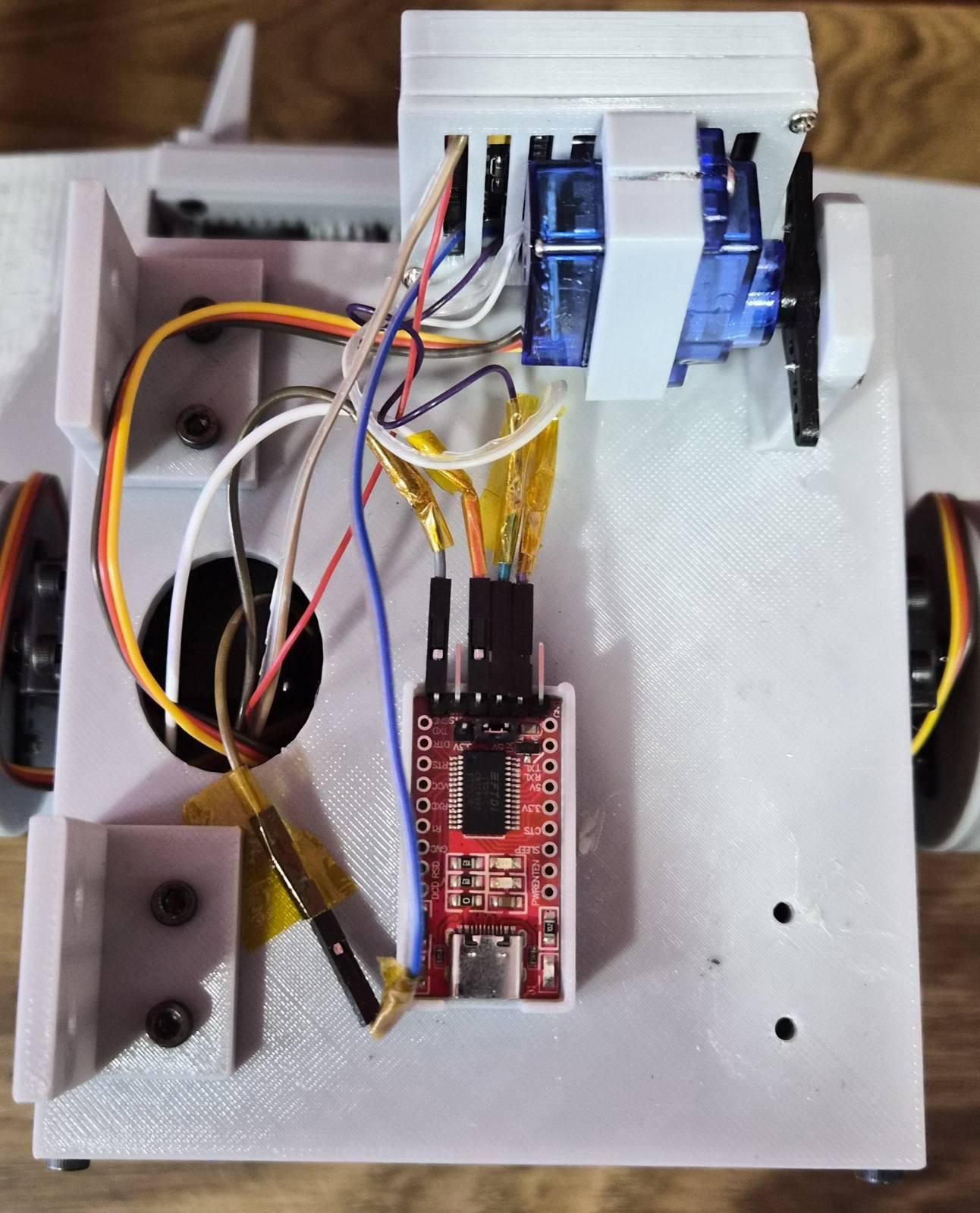
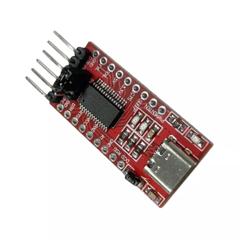
The last layer consists of ESP32 Cam (the Eye board), FTDI module (to program the ESP32 Cam) and MG90s servo (which rotates the board). The FTDI module is mounted as close as removable plate, so you can easily program the board.
The Arm
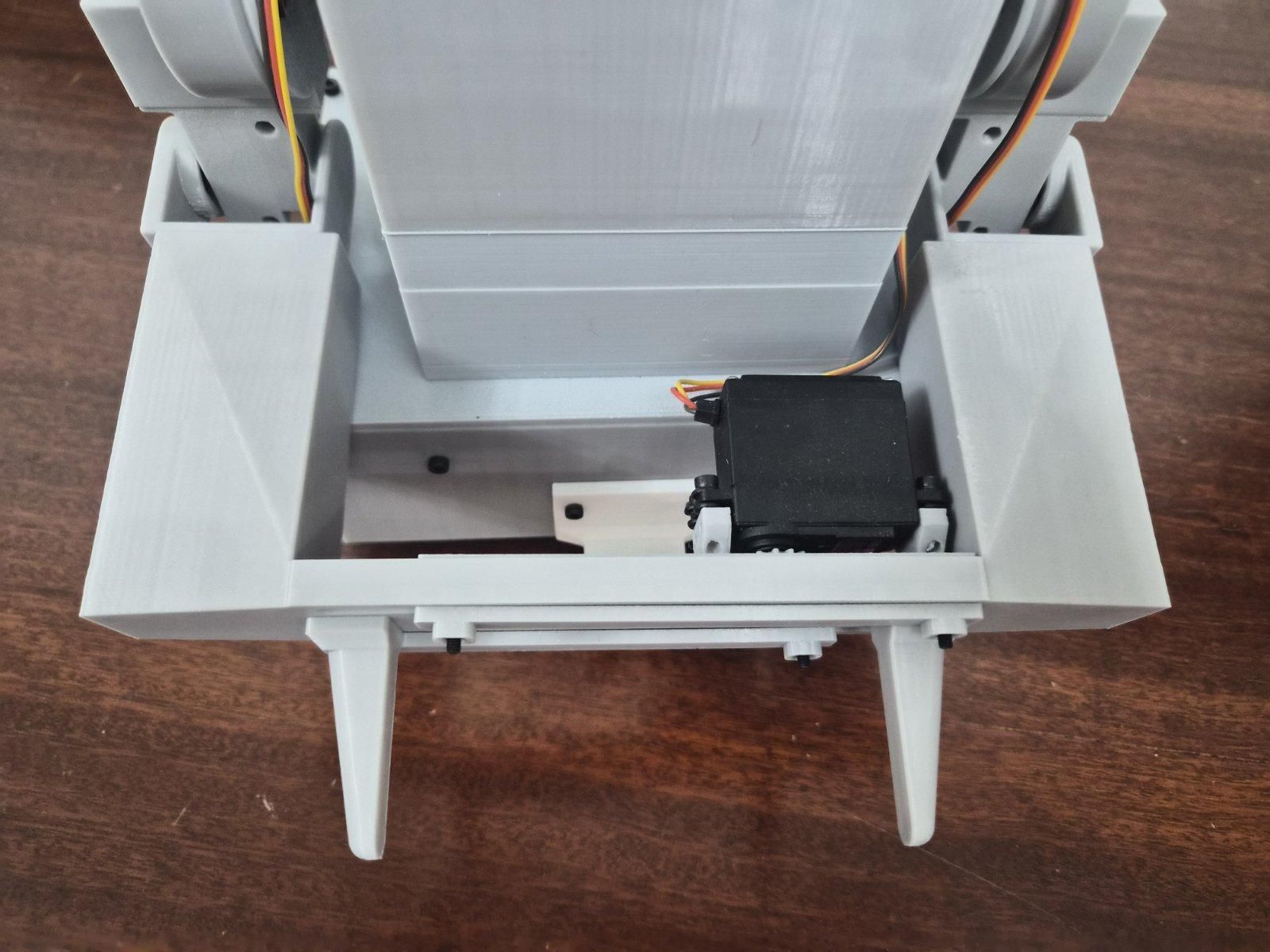
The arm is made out of 5 servos, three MG996R servos and two MG90s servos. Two MG996R are connected on the sides of the 3rd main chassis, which are the shoulders of the robot. For elbows I used two MG90s. I used the MG996R as the gripper of the robot, because of its high torque and power. Make sure you line up the servo angles correctly before securely screwing them on.
Upload the Software
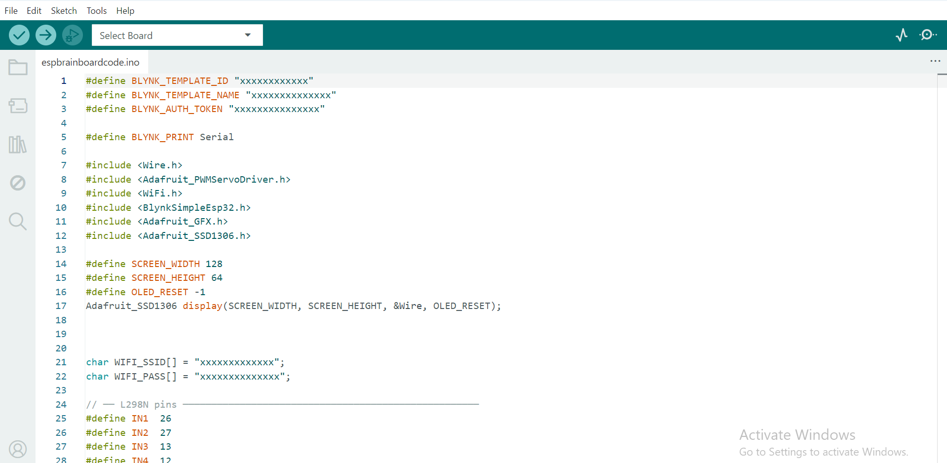
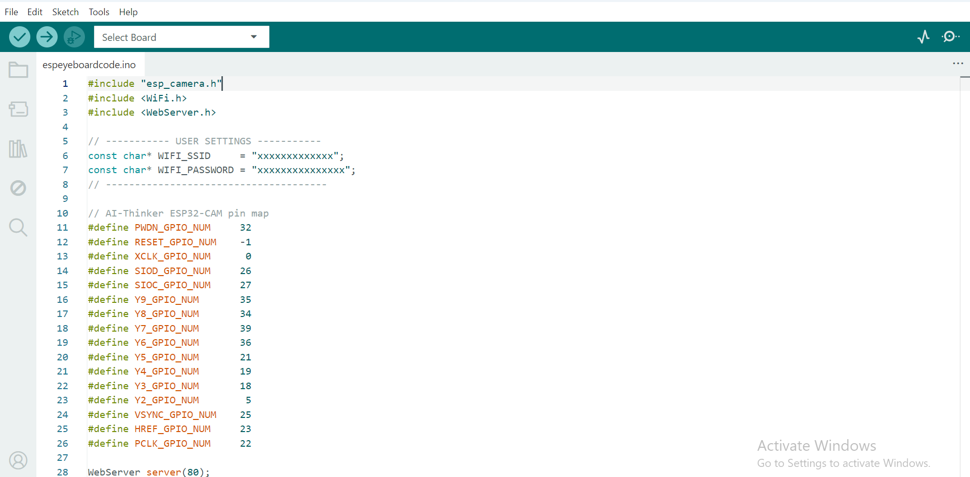
Upload the control program to the ESP32 and the camera program to the ESP32-CAM.
Install all of the required Arduino libraries before compiling the sketches.
After uploading the code, verify that the motors, servos, OLED display, and camera all operate correctly.
Configure the Blynk App
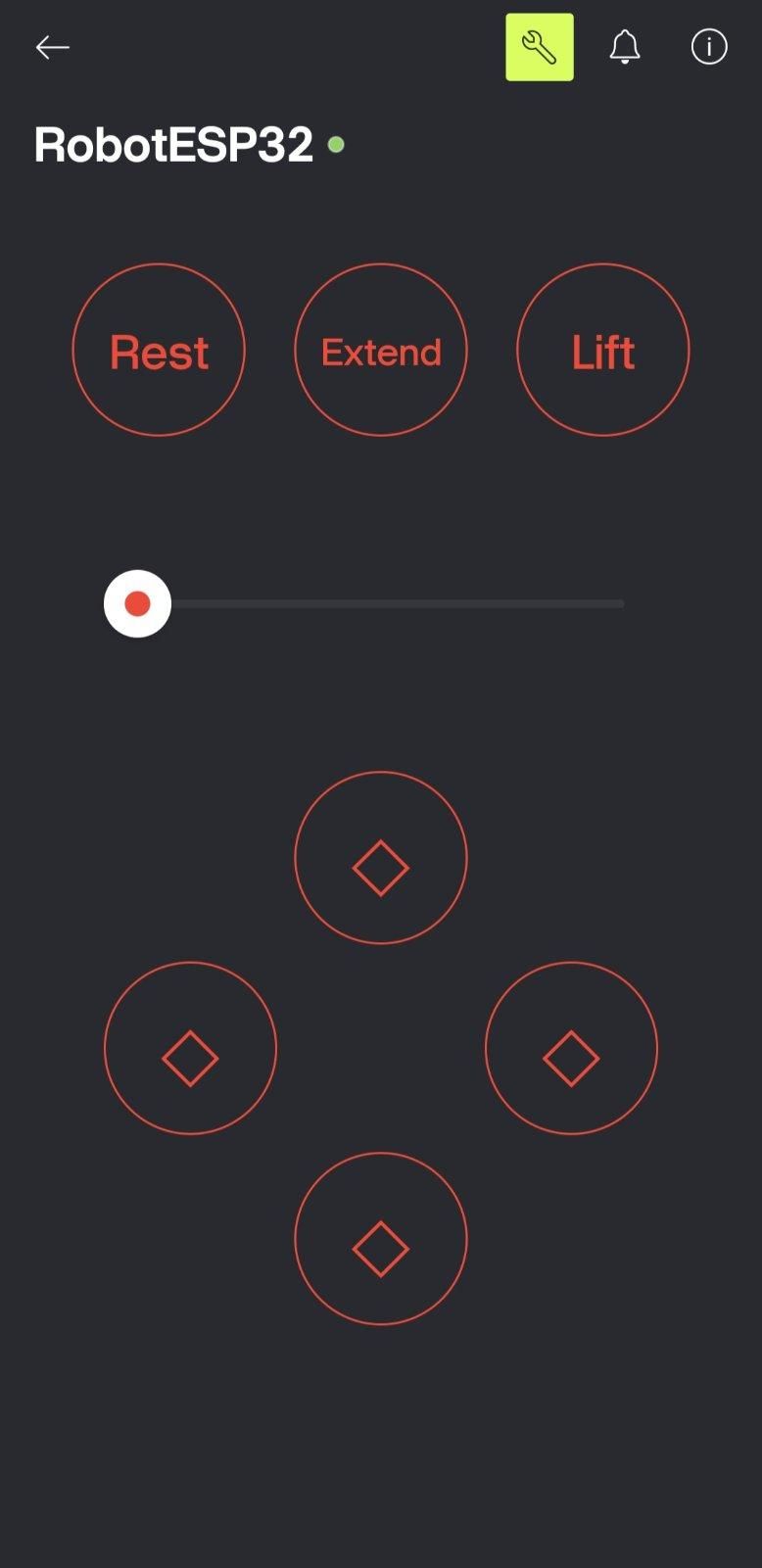
Create a new Blynk project and add the required buttons and sliders.
Assign each control to the correct virtual pin used in the code.
Once everything is configured, connect the robot to WiFi and verify that every control responds correctly.
Set Up the Live Camera
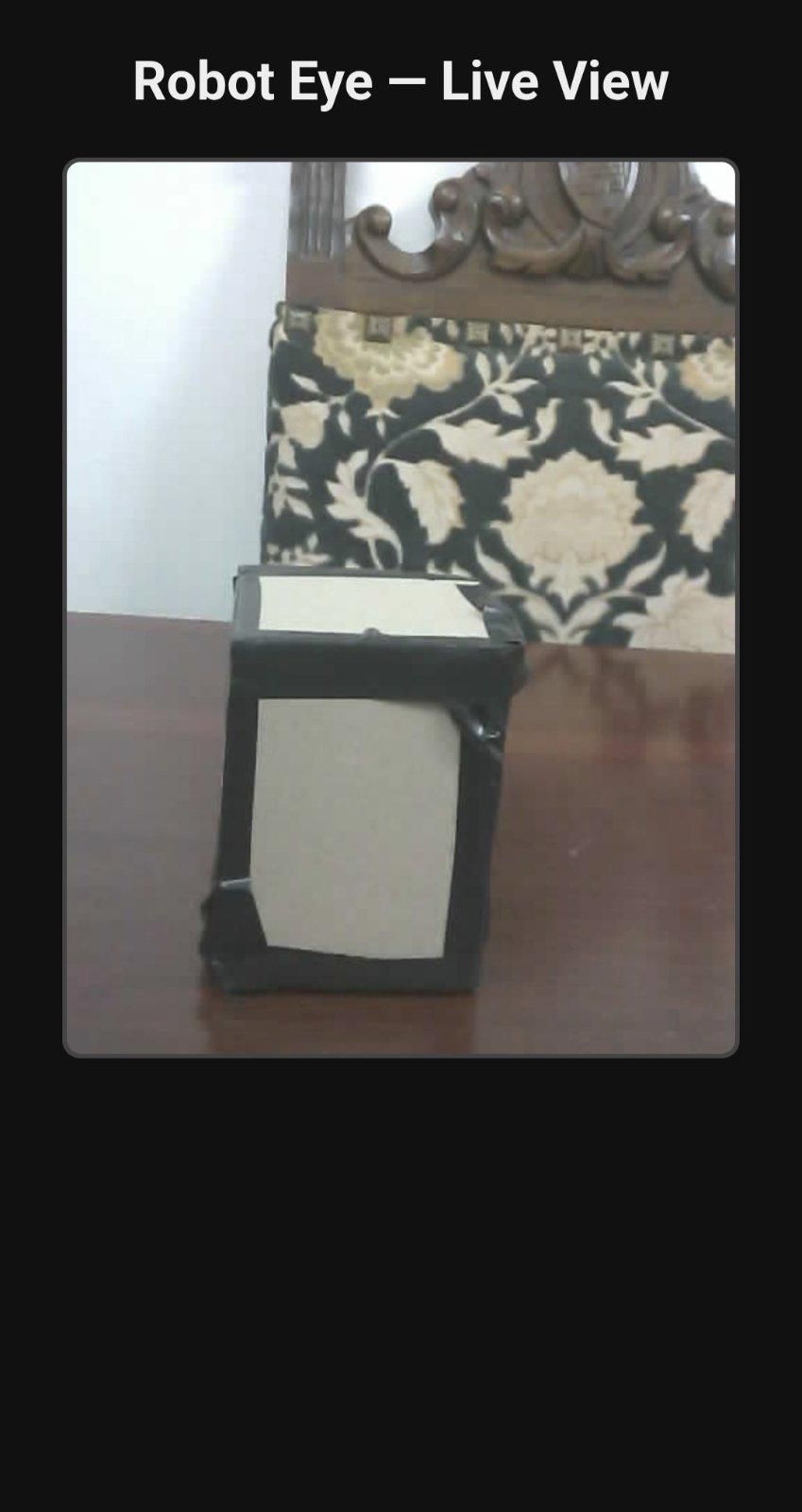
Upload the CameraWebServer example to the ESP32-CAM and connect it to your WiFi network.
Open the camera's IP address in your browser to view the live video stream.
Adjust the camera angle so you have a clear view of the robot's gripper while driving.
Operating the Robot
Turn on the robot and wait for it to connect to WiFi.
Open the Blynk app to control the robot and open the camera stream in your browser for live video.
Use the robotic arm to pick up small packages and transport them to their desired location.
The OLED display provides useful status information while the robot is operating.
Final Results
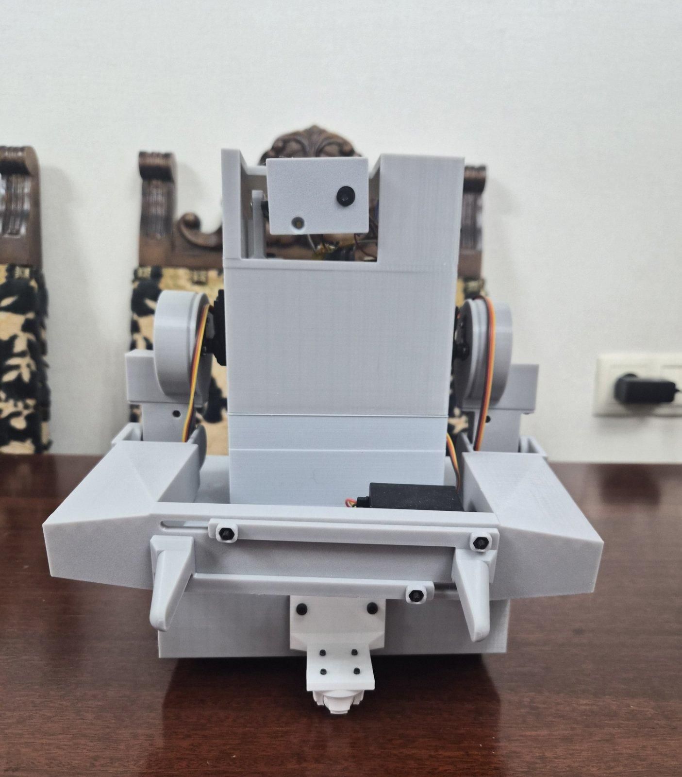
After completing the build, the robot is capable of driving wirelessly, streaming live video, and remotely picking up and transporting small packages.
This project combines robotics, wireless communication, embedded programming, and 3D printing into a single compact platform.
I hope this guide helps you build your own version or inspires you to create your own improvements.
Future Improvements
There are many ways this robot can be expanded in the future.
Possible upgrades include:
- Autonomous navigation
- Line following
- Automatic package sorting
- Color recognition
- Object detection using the ESP32-CAM
- Larger robotic arm
- Improved battery life
- Custom web interface
If you decide to build this robot, I'd love to see your version and any improvements you make!