Earthquake / Vibration Sensor
by sspence in Circuits > Arduino
21380 Views, 48 Favorites, 0 Comments
Earthquake / Vibration Sensor
We needed a method of detecting vibration in equipment, so I whipped up a simple vibration detector. One day, when the equipment was off, I saw that the detector was registering quite a bit of movement, even though I could not feel anything. I heard later that there had been an earthquake a few hundred miles away. That's when I had the "a ha" moment and decided to make a Seismic detector. Original article at http://arduinotronics.blogspot.com/2014/09/arduino-seismic-vibration-sensor.html
Parts:
Vibration Sensor - http://tinyurl.com/p3ej3fv
Arduino - http://tinyurl.com/pd3z4b4
16x2 LCD - http://tinyurl.com/n9rjk75
1 M Ohm Resistor - http://tinyurl.com/qdr2zox
Connections
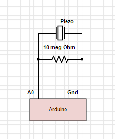
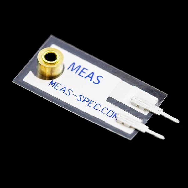
LDT0-028K
The vibration sensor connections are simple. Connect the + leg to A0, and the - leg to Arduino Gnd. Insert a 1 M Ohm resistor between the A0 and Gnd as well.
LCD
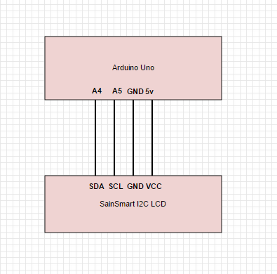
If you are using a I2C LCD, so there are 4 connections:
VCC - Arduino +5
SDA - Arduino A4
SCL - Arduino A5
Gnd - Arduino Gnd
There is special code and libraries required, see http://arduinotronics.blogspot.com/2014/09/arduino-seismic-vibration-sensor.html
If you are using a 16 pin parallel LCD;
The line in code:
LiquidCrystal lcd(12, 11, 5, 4, 3, 2);
resolves to the connections below:
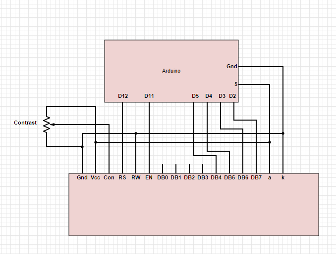
The circuit:
* LCD RS pin to digital pin 12
* LCD Enable pin to digital pin 11
* LCD D4 pin to digital pin 5
* LCD D5 pin to digital pin 4
* LCD D6 pin to digital pin 3
* LCD D7 pin to digital pin 2
* LCD R/W pin to ground
* LCD VSS pin to ground
* LCD VCC pin to 5V
* 10K potentiometer:
1. ends to +5V and ground
2. wiper to LCD VO pin (pin 3)
Code

I'm including the code here for the parallel LCD. Contact me if you want the I2C code. It requires special libraries, but only uses two data pins instead of 6.
//sensitivity variables
int minimum = 200;
int maximum= 1023;
int maxdelay = 400;
// include the library code:
#include
// initialize the library with the numbers of the interface pins
LiquidCrystal lcd(12, 11, 5, 4, 3, 2);
// Custom Character
byte seismic[8] = { B11111, B11111, B11111, B11111, B11111, B11111, B11111, B11111, };
//defines the pin connections
int sensePin= 0;
void setup() {
Serial.begin(9600);
lcd.begin (16,2); // or (20,4)
lcd.createChar(0, seismic);
lcd.begin(16, 2);
}
void loop() {
int reading= analogRead(sensePin);
Serial.println(reading);
reading = constrain(reading, minimum, maximum);
Serial.println(reading);
reading = map(reading, minimum, maximum, 0, 15);
Serial.println(reading); lcd.clear();
for (int i=0; i <= reading; i++){
lcd.write(byte(0));
}
if (4<=reading && 8>reading){
lcd.setCursor(0, 1);
lcd.print(" ");
lcd.print("Seismic Activity");
delay(500);
}
if (8<=reading){
lcd.setCursor(0, 1);
lcd.print(" ");
lcd.print("Earthquake");
delay(500);
}
delay(maxdelay);
lcd.clear();
}