Easy Arduino Light Following Robot
by JaceDuino in Circuits > Arduino
7802 Views, 18 Favorites, 0 Comments
Easy Arduino Light Following Robot

This is a tutorial on how to make a light following robot using Arduino, it has been simplified so that beginners can attempt this project too. This project should only take you at the most of an hour. I hope you enjoy.
Materials


Arduino Uno: http://www.freetronics.com.au/products/eleven#.VZn...
H-Bridge shield: http://www.freetronics.com.au/products/hbridge-dua...
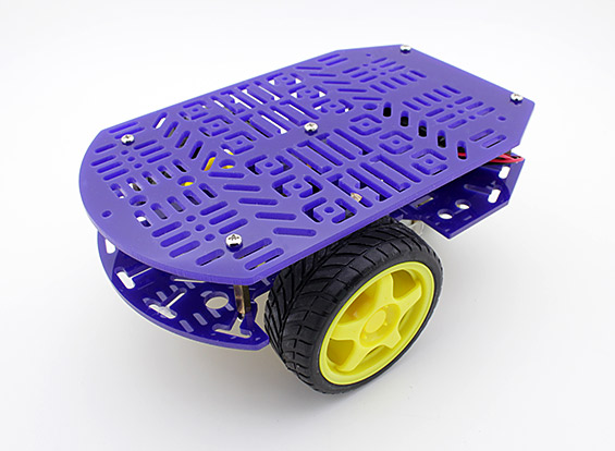
Chassis: http://www.hobbyking.com/hobbyking/store/__26249__...
2X LDR/Light Dependant Resistors
2X 100k Ω Resistors
Jumper leads
3X 9v
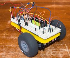
Wiring


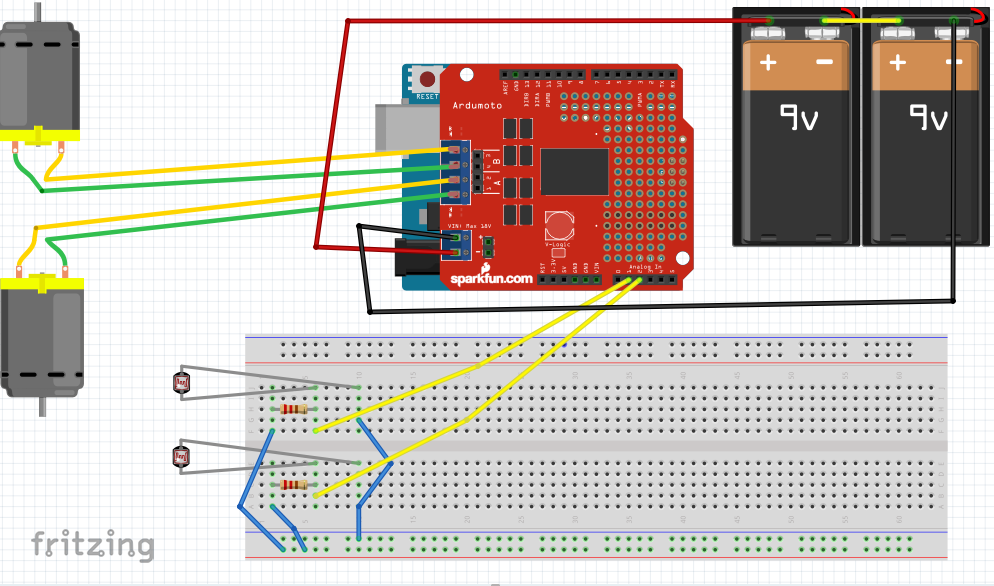

With the wires on the bread board that go to the side, 2 go to 5v on arduino and the other one goes to GND
It is easier to follow the pictures then me explain.
First, connect the H-Bridge shield to the Arduino Uno
Then, connect the LDR's, like in the diagram
After, insert the positive and negative of the motors in to the shield
*Now, connect 2 9v batteries in a series and then positive and negative to the spots on the shield
*Finally plug a 9v battery into the Arduino
(*Last 2 are for when you have uploaded the code)
Put It on the Chassis

Put the creation on your chassis how ever you please, make it look how ever you want as well. There is much I can say about this step though.
Code
Please respect that it took a while to figure out and write this code:
//Code by Jason McLaughlin
//2015
const int channel_a_enable = 6; //start motor a /left
const int channel_a_input_1 = 4; //positive/negative 1
const int channel_a_input_2 = 7; //positive/negative 2
const int channel_b_enable = 5; //start motor b /right
const int channel_b_input_3 = 3; //positive/negative 1
const int channel_b_input_4 = 2; //positive/negative 2
const int RightSensor = A1; // Read the right sensor
const int LeftSensor = A2; // Read the left sensor
// Variable definitions
int SensorLeft; // This stores the value of the Left Sensor pin to use later on in the sketch
int SensorRight; // This stores the value of the Right Sensor pin to use later on in the sketch
int SensorDifference; // This value is used to determine the difference between the Left and Right
void setup() {
pinMode( channel_a_enable, OUTPUT ); // Channel A enable
pinMode( channel_a_input_1, OUTPUT ); // Channel A input 1
pinMode( channel_a_input_2, OUTPUT ); // Channel A input 2
pinMode( channel_b_enable, OUTPUT ); // Channel B enable
pinMode( channel_b_input_3, OUTPUT ); // Channel B input 3
pinMode( channel_b_input_4, OUTPUT ); // Channel B input 4
pinMode(LeftSensor, INPUT); // Defines this pin as an input. The Arduino will read values from this pin.
pinMode(RightSensor, INPUT); // Defines this pin as an input. The Arduino will read values from this pin.
digitalWrite(A1, HIGH); // Enables LDR
digitalWrite(A2, HIGH); // Enables LDR
Serial.begin(9600); // Enables a serial connection through the Arduino to either USB or UART (pins 0&1). Note that the baud rate is set to 9600
Serial.println(" \nBeginning Light Seeking Behavior"); // Placed at the very end of void Setup() so that it is runs once, right before the void Loop() }
void loop() { SensorLeft = 1023 - analogRead(LeftSensor); // This reads the value of the sensor, then saves it to the corresponding integer.
delay(1);
SensorRight = 1023 - analogRead(RightSensor); // This reads the value of the sensor, then saves it to the corresponding integer.
delay(1);
SensorDifference = abs(SensorLeft - SensorRight); // This calculates the difference between the two sensors and then saves it to an integer.
// This section of the sketch is used to print the values of the // sensors through Serial to the computer. Useful for determining // if the sensors are working and if the code is also functioning properly.
Serial.print("Left Sensor = "); // Prints the text inside the quotes.
Serial.print(SensorLeft); // Prints the value of the Left Sensor.
Serial.print("\t"); // Prints a tab (space).
Serial.print("Right Sensor = "); // Prints the text inside the quotes.
Serial.print(SensorRight); // Prints the value of the Right Sensor.
Serial.print("\t"); // Prints a tab (space).
// This section of the sketch is what actually interperets the data and then runs the motors accordingly.
if (SensorLeft > SensorRight && SensorDifference > 75) { // This is interpreted as if the Left sensor reads more light than the Right Sensor, Do this:
analogWrite( channel_a_enable, 255);
digitalWrite( channel_a_input_1, LOW);
digitalWrite( channel_a_input_2, HIGH);
analogWrite( channel_b_enable, 255);
digitalWrite( channel_b_input_3, HIGH);
digitalWrite( channel_b_input_4, LOW);
Serial.println("Left"); // This prints Left when the robot would actually turn Left.
delay(50);
}
if (SensorLeft < SensorRight && SensorDifference > 75) { // This is interpreted as if the Left sensor reads less light than the Right Sensor, Do this:
analogWrite( channel_a_enable, 255);
digitalWrite( channel_a_input_1, HIGH);
digitalWrite( channel_a_input_2, LOW);
analogWrite( channel_b_enable, 255);
digitalWrite( channel_b_input_3, LOW);
digitalWrite( channel_b_input_4, HIGH);
Serial.println("Right"); // This prints Right when the robot would actually turn Right.
delay(50);
}
else if (SensorDifference < 75) { // This is interpreted as if the difference between the two sensors is under 125 (Experiment to suit our sensors), Do this:
analogWrite( channel_a_enable, 255);
digitalWrite( channel_a_input_1, HIGH);
digitalWrite( channel_a_input_2, LOW);
analogWrite( channel_b_enable, 255);
digitalWrite( channel_b_input_3, HIGH);
digitalWrite( channel_b_input_4, LOW);
Serial.println("Forward"); // This prints Forward when the robot would actually go forward.
delay(50);
}
Serial.print("\n");
}