ElectroLab: the Ultimate Trainer for Analogic and Digital Electronics!
by Jon G Aguado in Teachers > 9
926 Views, 5 Favorites, 0 Comments
ElectroLab: the Ultimate Trainer for Analogic and Digital Electronics!


The ElectroLab board is an educational electronic trainer designed to provide a guided and beginner-friendly approach to learning practical electronics. This versatile platform requires no prior knowledge and comes equipped with a large set of resistors and capacitors, multiple transistors, and a wide range of integrated circuits. With the ElectroLab, building your electronic circuits is made easy in just a few simple steps.
Want to get one?
How does it work?

The ElectroLab board contains more than 50 different components grouped by blocks:
- 30x Resistors (9 different values)
- 20x Capacitors (10 different values)
- 4x Diodes
- 5x Transistors (3 NPN & 2 PNP)
- 8x Operational amplifiers
- 14x Logic gates (4 ANDs, 4 ORs & 6 NOT)
- 4x JK Flip Flops
- 1x Audio amplifier
- 1x 555 signal generator
- 9x pushbuttons
- 1x resistive tactile sensor
- 3x potentiometers (two rotors and one slider)
- 1x microphone
- 1x photoresistor (LDR)
- 1x thermoresistor (NTC)
- 1 triaxial accelerometer
- 1x MQ-2 gas sensor
- 1 nine-led bar
- 1 RGB led
- 1 7-segment display
- 1 Speaker
By using this set of components, you can easily build your own circuit by connecting them directly with female-female DuPont wires to the corresponding pins of each component. The only limitation to the circuits you can create is your own imagination (and the availability of cables and boards, of course :D). These components have been thoroughly tested with various circuits that are ideal for learning basic electronics, such as:
- Oscillators with transistors, resistors, and capacitors
- Circuits with Op. Amps (sum, diff, integrator, etc)
- Analog to Digital converter with Op. Amps
- Combinational circuits with logic gates
- Sequential circuits with Flip Flops
- Counters with Flip Flops
- Binary to Decimal converter
- Square signal generators with the 555
- Timer with the 555
- Politone keyboard
- Audio amplifier with low/high passes
- Volume indicator with LED bar
- Horizontal level indicator with LED bar
The story behind ElectroLab
ElectroLab’s story goes back to 2016. By then I was finishing my engineering bachellor degree and working as educator and course coordinator for the Technological Campus of ICAI (CTI). This summer campus takes place in Madrid for 4-6 weeks and is addressed to pre-university students in the 14-18 years old range. The courses offered on the campus are normally 1-week duration 6 hours/day and aim to cover the basics of a specific topic (ie: robotics with Arduino, videogame design) in a very interactive and easy-to-follow way based on praxis and experimentation.
Among the courses I used to coordinate back then, the one on Electronics felt especially interesting for me: I wanted to offer a solid basis and at the same time let my students experiment in a safe way with each newly acquired concept. But the most important was to make it fun.
I had around 8 months to come up with the contents, the workshops, and most importantly: the electronic platform where to experiment with the course content (sensors, electronic components, etc). Back then, my experience pushed me away from breadboards, not because they were not a good solution, but because in a class filled with more than 10 students, debugging the mistakes committed on a breadboard (bad connections, components pins damaged by extensive usage, polarity misconnections) could become unsuitable for the given time.
Since it was the first edition of the Electronics course and we were not sure if it would succeed, the possibility of acquiring expensive and heavy electronic trainers was neither an option.
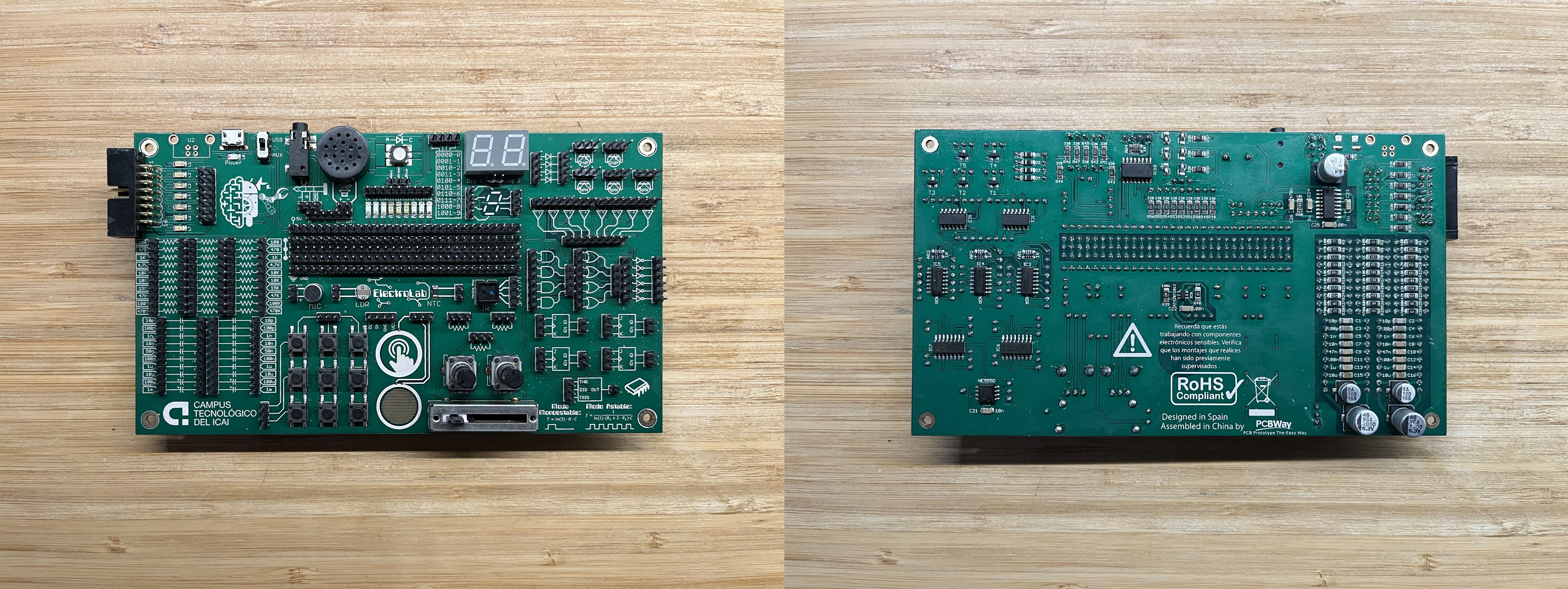
Instead, I kind of mixed both concepts in a compact, yet powerful, solution: the ElectroLab, a 175x100mm board that had on the top side the (male) pins and connectors for each component and on the bottom all the SMD components routed to each corresponding pin and ready to be used.
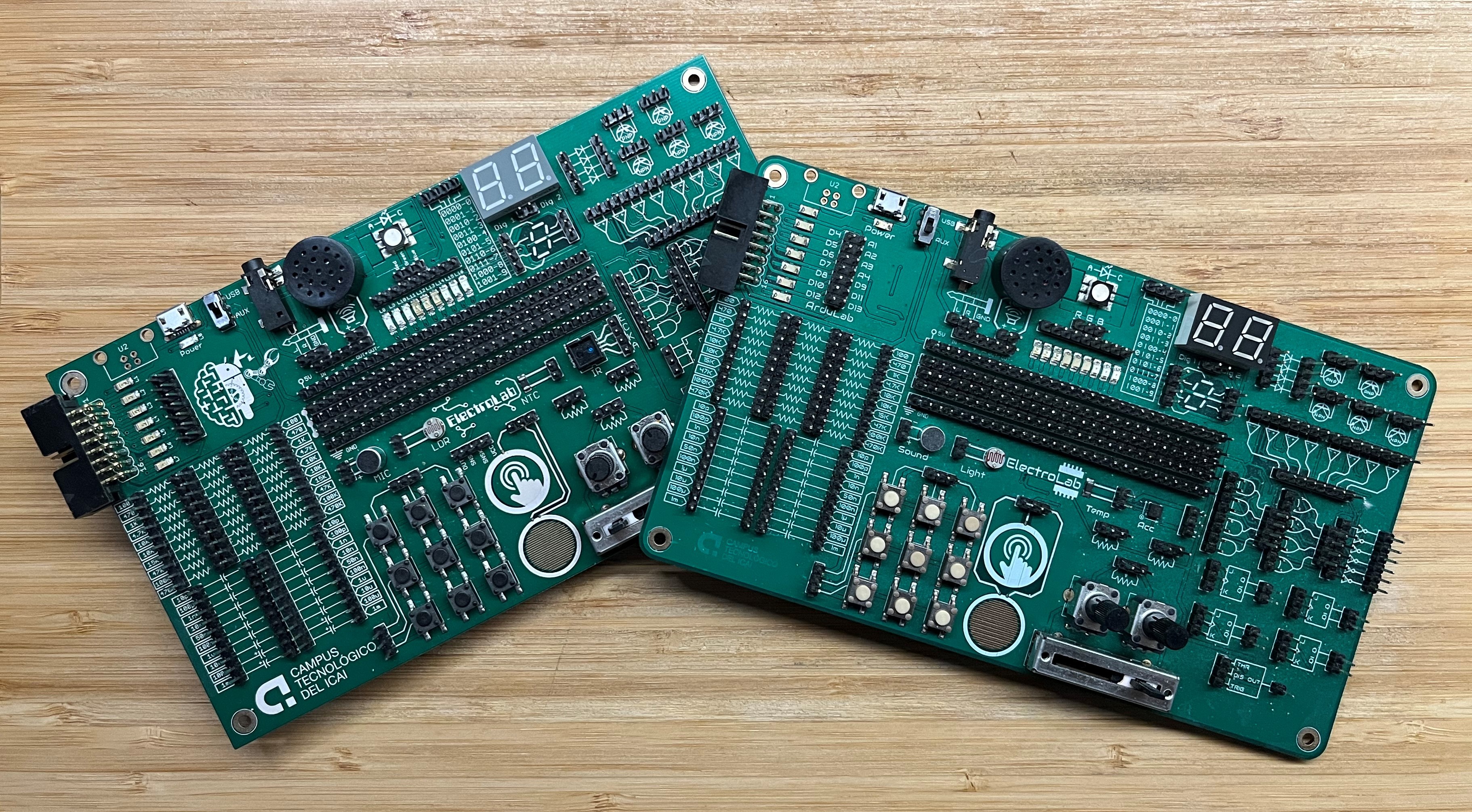
First generation (2016) of the board on the left, second generation (2020) on the right
ElectroLab Mk. I (V1)
The very first prototype of the ElectroLab cannot be considered one of my finest jobs. Except for the simplest components, most of the ones that required some kind of circuitry preparation didn't work correctly: the op. amps were not correctly powered, the flip flops and the logic gates had no pulled-down inputs (so were reading static noise while not receiving a clear 0/5V), the RGB led polarities were inverted and the BCD-to-7 segments display IC was not correctly routed.
To be frank, I'm still not entirely sure how I managed to mess up the design to such an extent. However, challenging situations like this often provide valuable learning experiences. The lessons I learned from that experience have been summarized into a checklist that I now try to follow whenever I order newly designed boards, things such as: checking that all the DRC on Eagle for unrouted pads or double checking the schematics.
After putting twice the pressure and spending two months on the first prototype, I was able to fix everything and ordered another set of PCBs to be assembled by myself: great success! This time, only minor bugs such as silkscreen issues or isolated mistakes were found. With my self-confidence restored, and a need to scale production for a first batch to be used on the Campus, I placed an order for 20 units (15 for the course and 5 as backup) that included assembly.
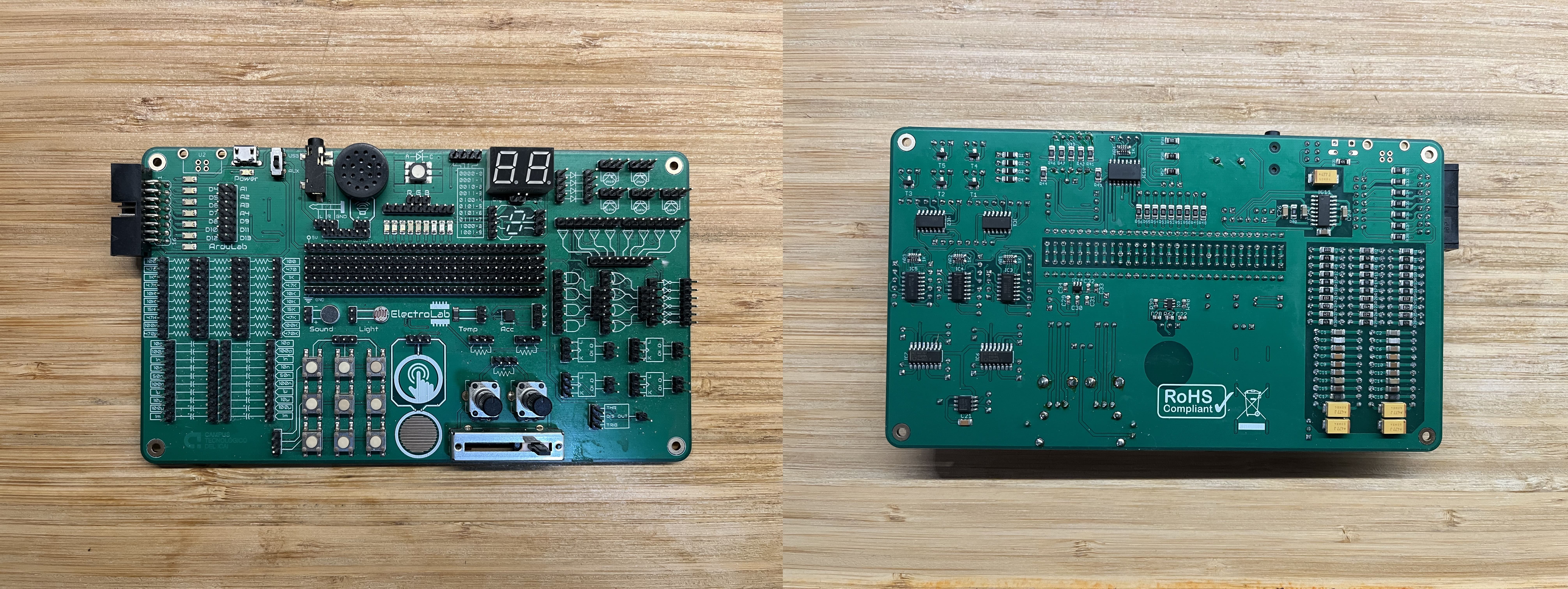
ElectroLab Mk. II (V2)
The next generation of the ElectroLab arrived after a few years as an update for the Mk. I. Most of the components were not modified according to the premise if something works fine: don't touch it!. However, some other components or systems really needed an update:
- The big electrolytic capacitors (>100µF) used to detach from the PCB as a result of lateral impacts on the component during the manipulation of the ElectroLab. They were replaced with smaller-size tantalum capacitors that, despite being more expensive, resulted tougher on the battlefield.
- The infrared sensor CNY70 was replaced with an analog accelerometer ADXL337, more educational and funny to play with.
- In general, the silkscreen was modified to simplify things and the corners were rounded for aesthetic reasons.
With these changes, the Mk. II replaced the Mk. I that had fallen in service and since 2020 they have been used simultaneously on the Campus.
ElectroLab Mk. III (V3)
Now, even though my journey on the Campus ended some time ago, the story of ElectroLab, far from dying, still advances.
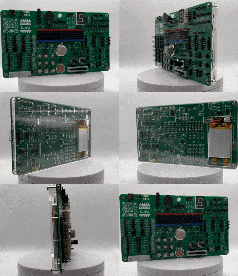
On the 3rd revision of the board, I combined all the best from previous versions while adding some quite useful features I applied on other recent projects: USB-C, LiPo battery support, reverse-side LEDs, 3.3V logic, etc.
I eventually replaced the capacitive touch sensor with a gas sensor (a MQ-2 by default but any other MQ sensor should work) and relocated some components to make them more intuitive.
As a result of the new tinkering around the board, a better production-oriented product came out. Since it has all the SMD components on the bottom side, the manufacturing costs for the SMD assembled version dropped significantly, making it way more affordable for anyone interested!
Supplies


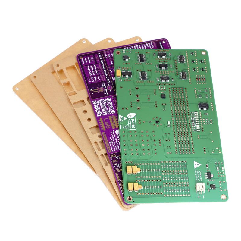
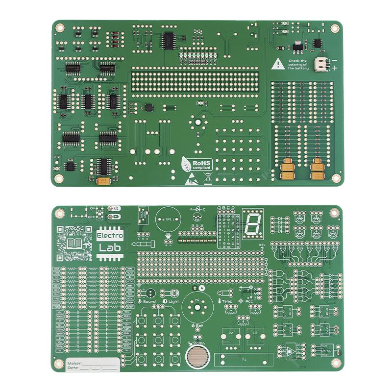
The ElectroLab kit, contains:
- 1x ElectroLab SMD preassembled board
- 1x ElectroLab Stencil PCB
- 3x different transparent acrylic plates *
- 1x 1000mAh LiPo battery *
- 4x Screw set (screw + washer + nut)
- 1x THT components set
- 40x Female-to-female jumper wires
*Are optional
Tooling
Tip:
Investing in quality tools will ensure a smoother and more precise soldering and electronics assembly experience, making your projects more efficient and successful in the long run.
Soldering Iron/Soldering Station:
Price range: $15 to $50 for a soldering iron, $50 to $150 for a station
Essential for joining electronic components. A soldering iron in the range of 25-60 watts and with a temperature range of around 300°C to 400°C (572°F to 752°F) should cover most electronics soldering tasks.
Regarding the tip, a fine conical or chisel tip is generally recommended for electronics work, as it provides precision and control. Tip size can vary, but a tip with a width of around 1mm is often a good starting point for most projects. Some soldering stations offer interchangeable tips, allowing you to select the most suitable one for your task.
Solder Wire:
Price range: $5 to $15 (100g spool)
Material used to create electrical connections. Common diameters for electronics work include 0.8mm (0.031”), 1.0mm (0.039”), and 1.2mm (0.047”). Thinner solder (e.g., 0.8mm) is suitable for fine, delicate work, like the ElectroLab soldering, while thicker solder (e.g., 1.2mm) can be used for larger components and wires.

There are two main types of solder: leaded and lead-free. Each has its own considerations:
- Leaded Solder (e.g., 60/40 or 63/37):
- Leaded solder contains a small percentage of lead, which can provide smoother solder joints and easier flow.
- It has a lower melting point (typically around 183°C or 361°F), making it easier to work with.
- Ensure proper ventilation or use a fume extractor when using leaded solder to avoid inhaling lead fumes.
- Wash your hands thoroughly after handling leaded solder and components.
- Lead-Free Solder:
- Lead-free solder is environmentally friendly and complies with RoHS regulations.
- It has a higher melting point (typically around 217°C or 422°F) compared to leaded solder, so you may need to adjust your soldering iron’s temperature settings accordingly.
- Lead-free solder may require slightly different techniques, such as holding the soldering iron tip on the joint for a slightly longer time.
- It’s generally considered safer in terms of health and environmental impact but can be less forgiving for beginners due to its higher melting point.
Cutting Pliers:
Price range: $5 to $20
Used for trimming excess leads and wires after soldering. Look for sharp, precision-ground jaws, ergonomic handles, and corrosion-resistant materials.
PCB Clamp:
Price range: $10 to $30
Although this is more of a personal choice and not a required tool, a good PCB clamp will secure your board during soldering and help you with the assembly. Choose one with adjustable clamping pressure, a non-marring surface, and a stable base or attachment mechanism.
Screws Positioning
Pins Placement
Start with the pinheads. Place all the pinheads on the ElectroLab top side. Make sure you introduce the short side of the pin on the PCB.
Once you have mounted all the pins, place gently the Stencil board over it. Be patient, some pins (like the individual pin from the signal generator or the Gas sensor) may become trouble rebels. Once they are all in place, screw the other 2 nuts to the screws to secure the two boards together.
Pins Soldering
With the pinheads correctly secured, proceed to the soldering of each individual pin on the ElectroLab’s bottom side. Pay special attention to those solderings close to SMD components to avoid any damage.

Stencil Removal
THT Components Soldering
Continue with each individual THT component, starting from the smaller like the switches and sensors. In this case, is highly recommended to:
Warning
Some components have polarity, which means they have to be assembled on a specific way, pay attention to the marks under the sensor. Those THT components are the speaker, the microphone, the RGB led and the 7 segments display.
1. Place the component on the top side of the board
2. If it has long pins that can bend (like the LDR sensor), bend the pins to keep it in place. If not, press it to hold it in position while soldering (like the speaker).
3. Start by soldering just one of the pins.
4. Check if the sensor is still in the correct position and correct it if not.
5. Solder the rest of the pins and cut the excess length of them.

Attention
Please exercise caution when trimming the excess metal from soldered pins. Wearing safety glasses or goggles while performing this task is strongly recommended to avoid potential eye injury.

