Electromagnetic Photo Wobbler
by janw in Circuits > Microcontrollers
7348 Views, 19 Favorites, 0 Comments
Electromagnetic Photo Wobbler


I have entered this instructable into the kynetic sculpture contest so if you like it then please vote for it.
How Does It Work?
There is a magnet attached to the base of the pendulum. When a current is applied to the coil next to the magnet, it becomes magnetic and thus it gets a magnetic field. The magnet is attracted to the coil and pulls the pendulum to one side. When the magnetic field disappears the pendulum swings to the opposite side.
On the opposite side, there is a reedswitch that is activated then the magnet passes it. The reedswitch is connected to a microcontroller that will activate the coil again when the pendulum is on its return swing.
And then everything starts over again.
This device also has LED's that get activated when the ambient light drops under a certain level. It is done by using a LDR (Light dependant resistor) and the ADC channel of the microcontroller.
What Do You Need?


Most of the parts that I used for this project are recycled bits or things that where lying around on my desk.
You need:
- A coil (I dismantled a broken relais to get its coil)
- 1 small but strong magnet
- A reed-switch
- A clip for a 3V batter
- A 12V adaptor
- An attiny45 and programmer
- A TLP504a optocouple
- A LDR
- 3 150Ohm resistors
- A 1.5KOhm resistor
- 2 1KOhm resistors
- A 10KOhm resistor
- A 100nF capacitor
- 2 dip8 IC sockets
- 3 green LED's (or other colour)
- A 2N3904 transistor
- A BD137 transistor
- A 1N4007 diode
- Some board or PCB's to solder everything on
- A bit of wire
- Some acrilic
- A little clamp to hold the photo
- A needle or something similar to use as axis
- Glue
- Soldering Iron and solder
- A small drill (I used 0.8mm)
- Something hot to bend the acrylic like a hot air gun
I used some smd components but ofcourse you are free to use regular stuff.
Designing the Electronics: the 12V Side.


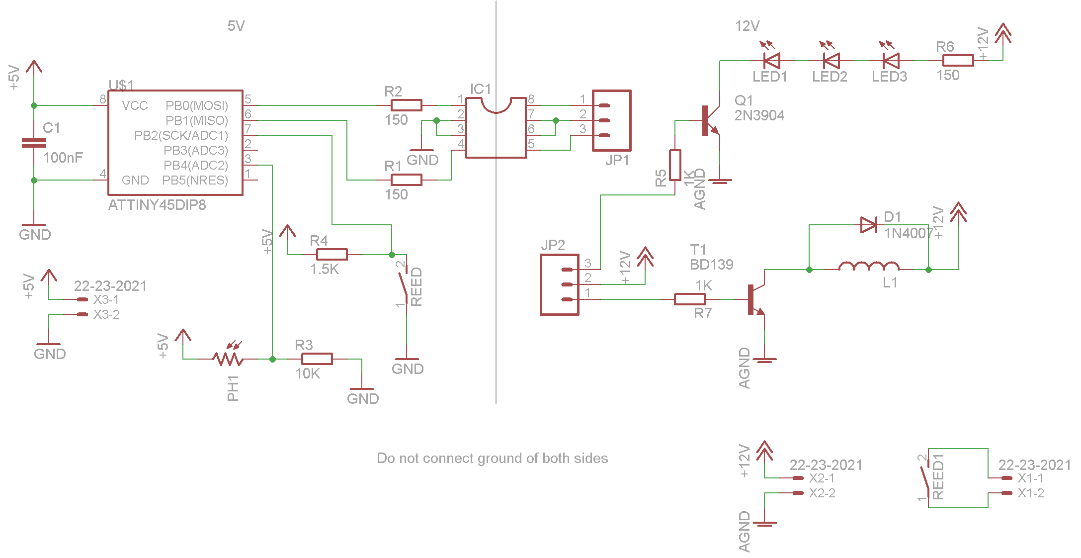
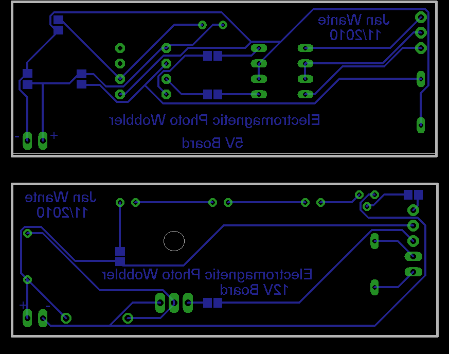
I divided the electonics into 2 parts, divided by an optocouple: a 5V part and a 12V part. Why? Very simple: Large coils (like motors and magnets) are not the best friends of your microcontroller. You can fry a lot of microcontrollers if you don't separate the two. An optocouple is the best way to do that because it has really nothing but so light that connects one side with the other.
On the downside: an optocouple only allows a few mA's to pass so you will need some extra transistors to drive the loads.
I used a TLP504a optocouple because I had two of them lying around and they suited me well as they have room for two signals. The same for the transistors: I had them lying around so you could use other types with similare characteristics.
An important part on the 12V side is the diode. It will drain the coil when the power is turned off and so will protect it against a high voltage pulse. That pulse is caused by the electromagnetic field when it disappears. It is mouted 'in the wrong way' but believe me thats the right way for now.
Downloads
Designing the Electronics: the 5V Side.


On the 5V side, we have 3 important components: An attiny45, a LDR and the other halve of the optocouple.
The attiny45 will act as the brain of our contraption. It will read the values of the LDR and decide whether or not to turn the leds on and it will get the pulses of the reedswitch and turn the coil on at the right moment.
The LDR will 'sense' the ambient light in the room. It is connected to the adc of the microcontroller which will translate its data into switching the LED's on or off.
Don't forget to add two 150Ohm resistors to the inputlines of the octocouple. Inside are leds and just like with any led you will need that resistor to prevent it from frying.
Downloads
Solder Your Electronics


Don't add the coil and the reedswitch yet. I will tell you why later.
Making a Case and Pendulum.


Some things to think about:
- Make your case wide and heavy enough otherwise it might tumble down when the pendulum starts to swing.
- Make sure the pendulum can swing freely.
- Make sure the holes for your axis are aligned well, otherwise your pendulum will not rock smoothly.
I had my parts CNC-milled so the machine made sure that everything was aligned well. the dimensions are roughly 75mm x 30mm x 100mm.
I added a nut and bolt on the lower part of the pendulum as a weight. This weight is needed to give the pendulum its momentum. This momentum makes sure that the pendulum keeps swinging. This is very important as the magnet is strong enough to stop the pendulum when it hovers over the reedswitch.
The weight is also needed to counter the weight of the photo.
I used a needle as the axis for my pendulum. Therefore I dilled two holes of 0.8mm in the case and one in the pendulum. The pendulum is secured onto the axis with glue and the axis itself is held into place by two bumpons that cover the ouside of the holes.
Make sure that the pendulum cannot swing into any other direction than the desired one. Otherwise it will wobble all over the place.
The clamp for the photo is simply glued into place.
Putting Everything Together.


Determine how heigh your reedswitch should sit by moving you pendulum over it. It should not hinder the pendulum mechanically or magneticly. If it is fitted right, you should hear the telltale clicking of the switch when the magnet passes over it. Make sure that your pendulum still swings freely before you solder the switch. At the same time, solder the two wires for the coil.
Now you can glue both boards into place.
As you can see in the second picture, the coil is outside of the case and mounted onto a strip of acrylic that can slide in and out. It was my original plan to mount it on a fixed place on the case but then I noticed that different photos give different swings of the pendulum. We could adjust the timing in the microcontroller but that means that we would have to reprogram it every time. By making the position of the coil adjustable, the problem was fixed.
Programming It.

I wrote my code in Bascom.
$regfile = "attiny45.dat"
$crystal = 8000000
Config Portb.0 = Output
Config Portb.1 = Output
Config Portb.3 = Input
Config Portb.4 = Input
Dim W As Integer
Config Adc = Single , Prescaler = Auto
Start Adc
On Int0 Button 'Reedswitch
Enable Int0
Enable Interrupts
Portb.1 = 0
Portb.0 = 0
Do
W = Getadc(2) 'Sets the leds
If W > 400 Then
Portb.0 = 0
Else
Portb.0 = 1
End If
Loop
Button:
Portb.1 = 1 'Drives the coil
Waitms 125
Portb.1 = 0
Waitms 125
Return
End
Notes
www.sheepdogguides.com/arduino/aht8pendu.htm
Special thanks to Izaak and Angelo who helped me with the cnc milling of the case.