Ember Build Head Display Case
by Porda in Workshop > 3D Printing
4916 Views, 52 Favorites, 0 Comments
Ember Build Head Display Case

Do you need a way to safely transport your unprocessed Ember prints or simply need a snazzy way of displaying said prints? Have we got a product for you!
In preparation for a trade show in New York, I designed these cases to protect the unprocessed prints during transportation but also to work as impromptu display cases. If you'd like to see the design process, keep reading. If you know what you're doing and would just like the DXF cutting files, please skip to the last step.
If you want more info about the Ember printer, check out the site. Autodesk Ember
Special thanks to:
Brian, bad-zima, for showing me MakerCase
Pierre, ppalin, for helping me with each revision of the case.
Requirements

Hardware:
- Epilog laser cutter
Software:
- Inkscape
- AutoCAD (or other 2D sketching software)
- Inventor (or other 3D modeling software)
Materials:
- 1/8" clear acrylic
- 1/8" plywood
- acrylic cement
- superglue
Start With MakerCase

MakerCase is a neat website that allows you to generate 2D plans for a laser-cut box based on overall dimensions, material thickness, and size/style of joints.
You can go to the website and input the dimensions as shown in the above image or, because we'll all be using the same dimensions, you can download the attached .svg file.
Downloads
Convert SVG to DXF


Because I'll be using AutoCAD and Inventor, like a genuine Autodesk fanboy, I'll start by converting the SVG to DXF with the help of Inkscape. Inkscape is a free vector graphics program, but we only need it for its converting abilities. If you know what you're doing and prefer to use different programs, you can still follow my design choices and general flow.
After we've opened our file in Inkscape we need to select all objects, CTRL+A, and then convert all of them to paths by selecting Path > Object to Patch or by alternatively pressing SHIFT+CTRL+C.
Now that all of our objects are now paths, we can go to File > Save As... and select .DXF from the drop-down menu.
You can also use the attached DXF if you prefer to skip using Inkscape.
Downloads
DXF to 3D Components

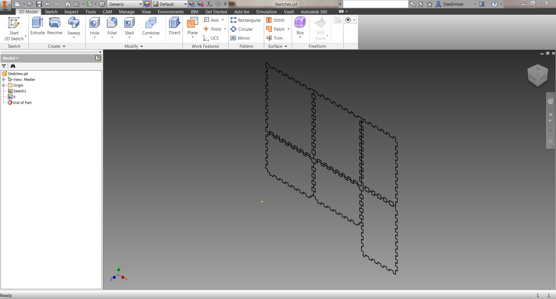
In order to effectively model the alterations to the standard box, I created a 3D model around the build head to check clearances and design intent.
We'll want to first create a new part and start a sketch. Once in the sketch, you can select the ACAD button shown in the above picture to insert the DXF from the last step.
Once imported, we can select one of the paths, copy it (CTRL+C), open a new part, start a new sketch, and paste (CTRL+V) the path.
The next step is a little odd and requires it's own title. . .
Close Sketch and Extrude

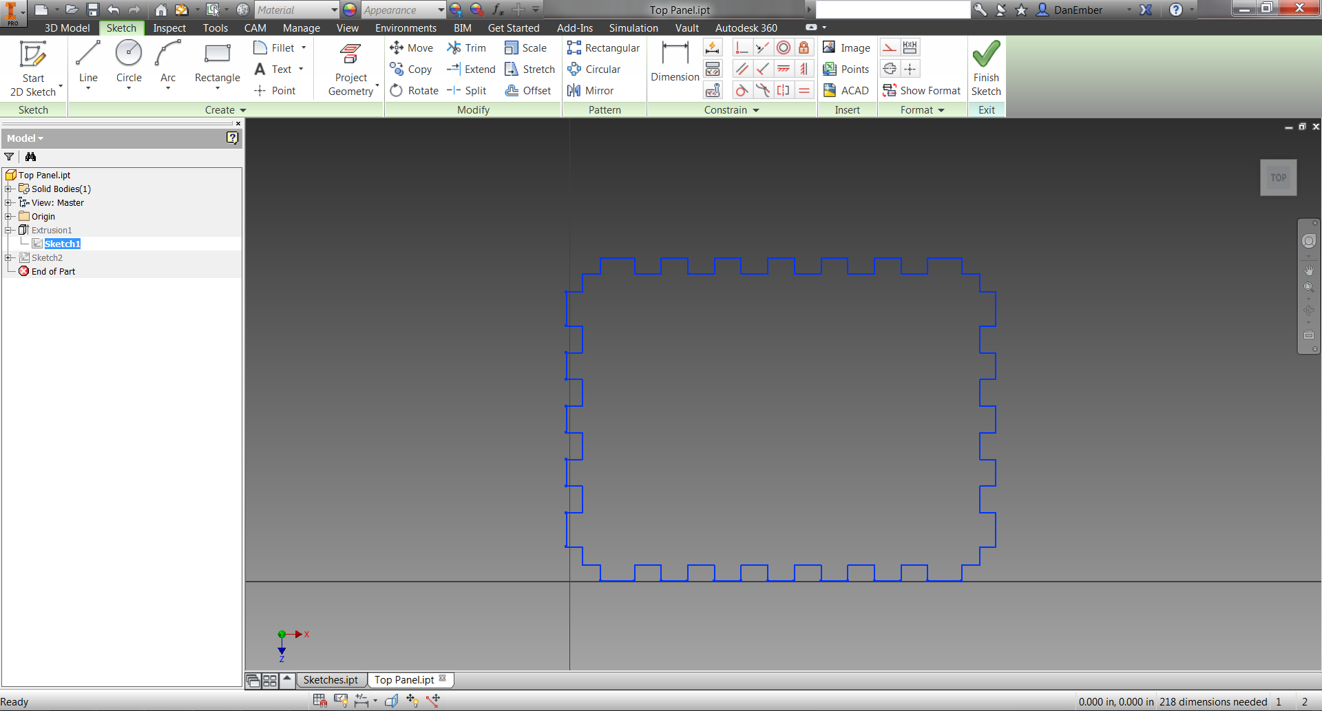
An interesting problem that arises with the path we pasted is that it's not actually closed and therefore can't be extruded.
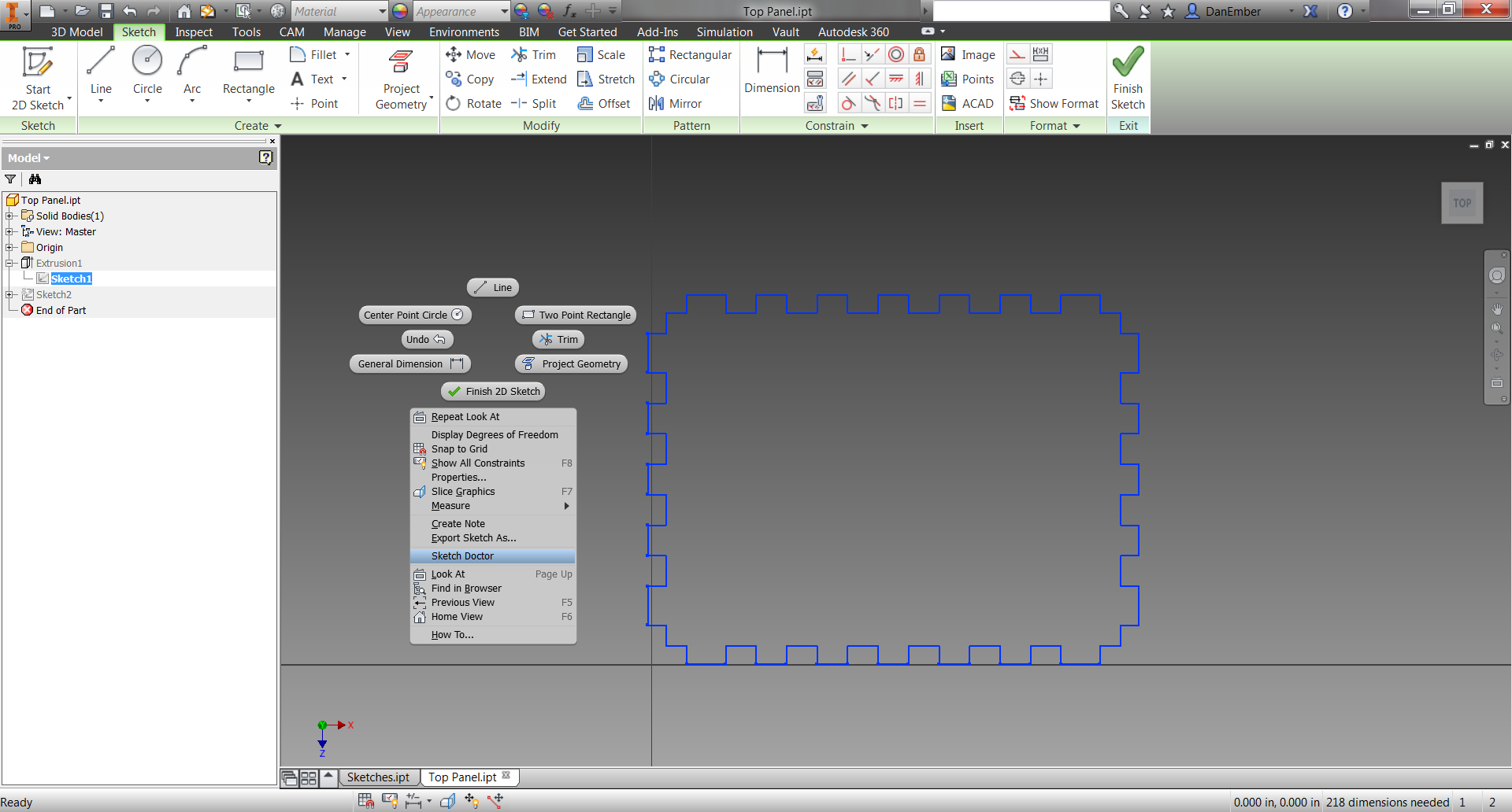
The trick to closing the sketch is to merge all of the redundant points where the lines intersect. We can do this by right-clicking in the sketch window to access the drop-down menu and then selecting Sketch Doctor.
After following the prompts to diagnose, examine, and treat, you will then go through an awesome mini-game where you click, or press Enter, as fast as you can until the text boxes stop popping up.
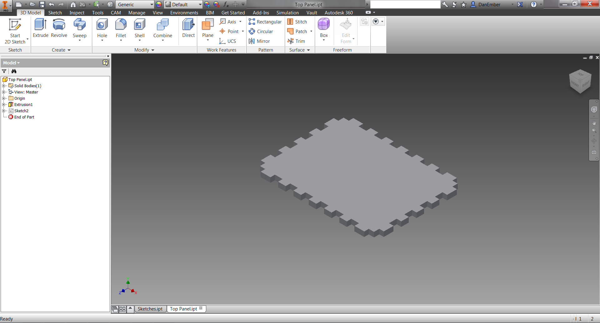
Once the sketch is closed, simply exit sketch mode and extrude the profile to 1/8".
Modify the Panels
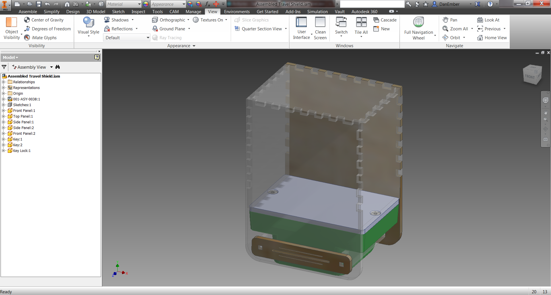
Once you repeat the following two steps for the other two unique profiles, Side and Front as I've referred to them, you're ready to start modifying them to the build head.
Because the build head model is unfortunately not open yet, I can't share it at this time. I can however provide the models for the case.
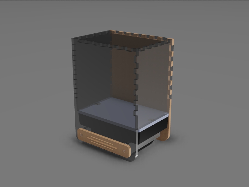
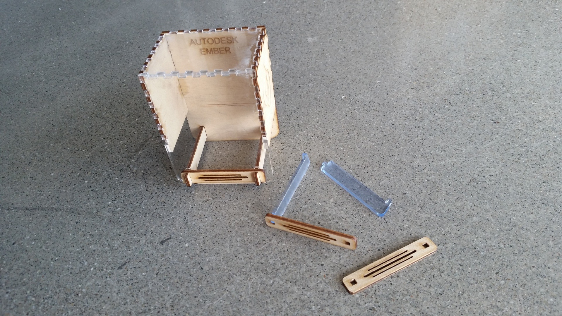
A quick overview of the design:
the side panels are designed to rest on the face of the build plate to prevent the top of the case from smashing the print. The front panel extends past the build plate to prevent the case from moving forward and backward and again smashing the print. The slide through pieces, called Keys, secure the case around the build head and prevent the left and right motion that would cause the side panels to smash the print. The Key Lock is then the piece that locks the keys in place and prevents them from sliding out in transit.
To see how the design developed over iterations, check out Step 9.
3D Model Back to DXF


After the panels have been modified fit around the build head and verified in the 3D assembly, we need to convert them back to DXFs.
To do this we simply start a new sketch in the part file, preferably using the face of the part as the sketch surface, then select Project Cut Edges from the Project Geometry pulldown. This will convert the entire part profile into sketch lines.
Now we can simply right click the sketch in the model tree and select Export Sketch As...
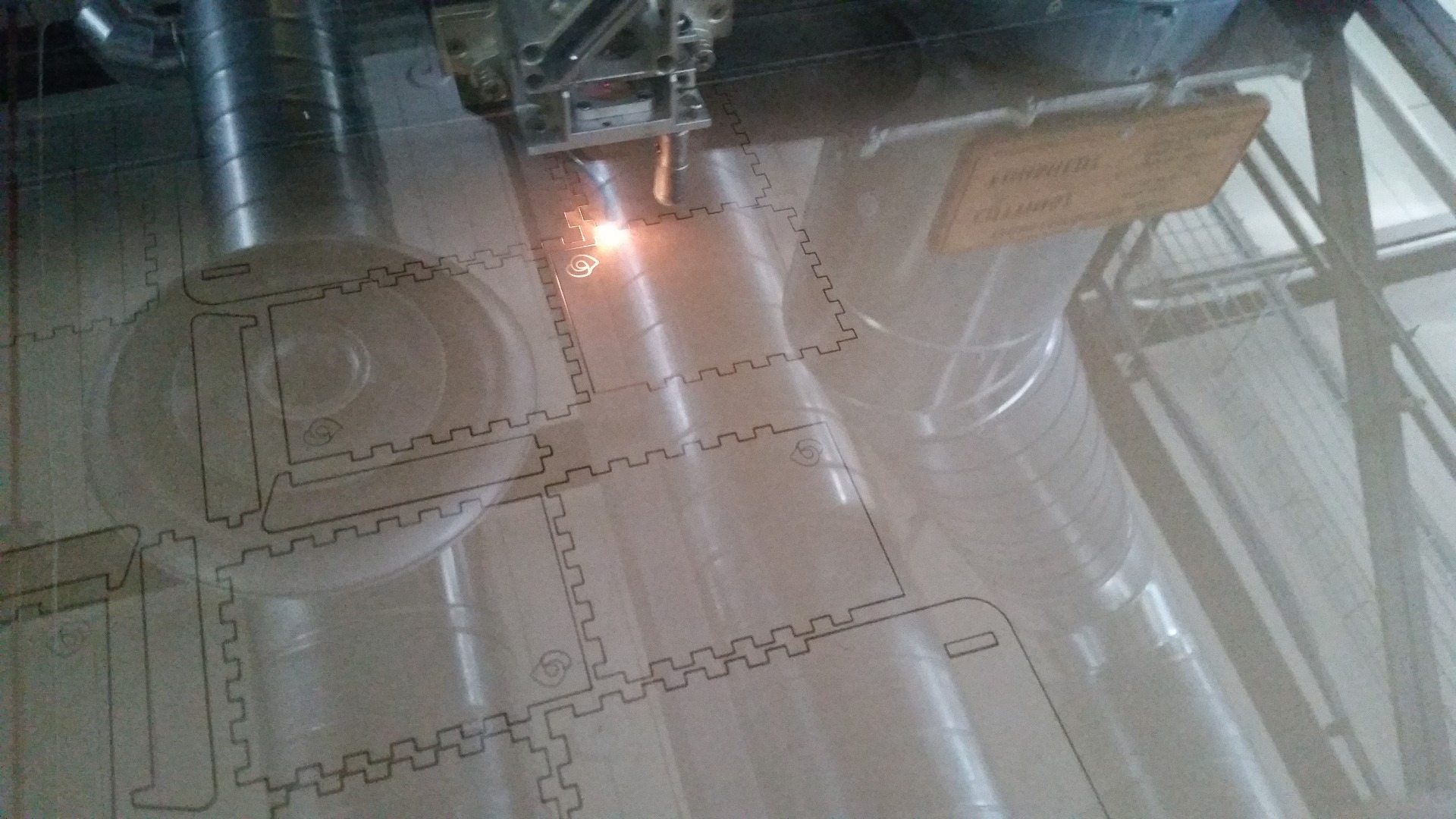
DXF to Laser Cutter
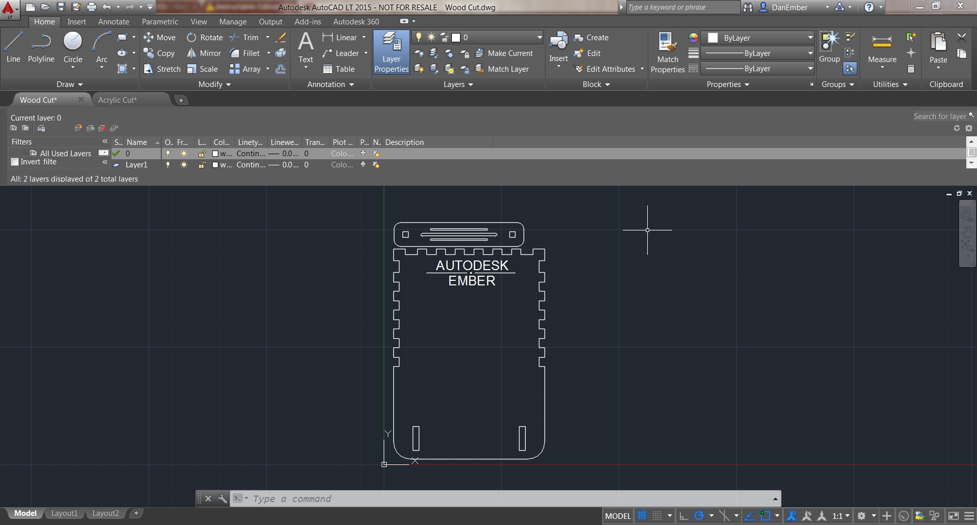


With the new DXFs, we can use AutoCAD to orient our paths for laser cutting. This is also where we can insert other vectors to be etched into the panels.
For cutting lines, Vectors, we set a line width of 0.00 and for etching, Raster, we can use any other line thickness.
Once the parts are aligned and the lines are the correct thickness, we simply Print the page. Your print settings will likely be different than the ones I used, but I've included pictures of mine for reference anyways. Be sure to print at 1:1 scale and in the Advanced Printer Properties to select Combined cutting, which is Vector and Raster.
Design Changes


In chronological order. Read through the comments on the pictures to see how the design changed with each revision.
Final Results and Further Steps


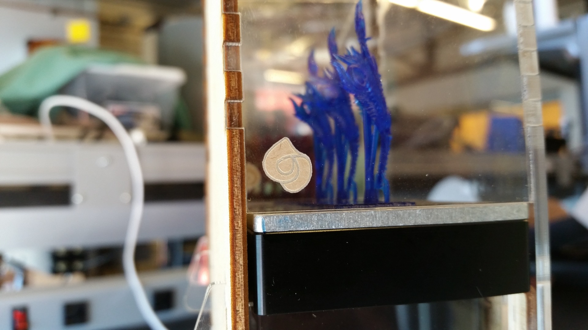
You can see the finished boxes above as well as the awesome jewelry prints displayed at the MJSA booth in New York. The boxes are held together with a combination of acrylic epoxy and super glue, but you can use whatever adhesive you have on hand.
I've also posted the final cut files again for anyone that may have skipped to the end.
Further Steps
- Cooler etched images! I designed these pieces in a hurry so the raster images are nice but not as spiff as they could be.
- The ability to change the height using an online form would be a neat way to customize the box to your print.
- Reports from MJSA say that the Key Lock piece can be loose and fall off the keys. This could be from expansion of the wood, so a plastic lock may work better.
If you make a display case yourself or modify the design, please let me know. I'd love to see what you do.
And if you need help printing cool things to transport or simply want to know more about Ember, check out the Instructables group, Ember.
Magnetic Upgrade


Based on reports from the trade show that the press fit between the keys and key lock can loosen over time, I made a magnetic upgrade with two 1/4 x 1/16 magnets and four 1/16 x 1/16 x 1/4 magnets.