Ender 3 Clay Printer Conversion
by chrisweedonart in Workshop > 3D Printing
4383 Views, 22 Favorites, 0 Comments
Ender 3 Clay Printer Conversion


Since first publishing this Instructable and using the setup I have made some additional tweeks which I have highlighted in the text using Italics.
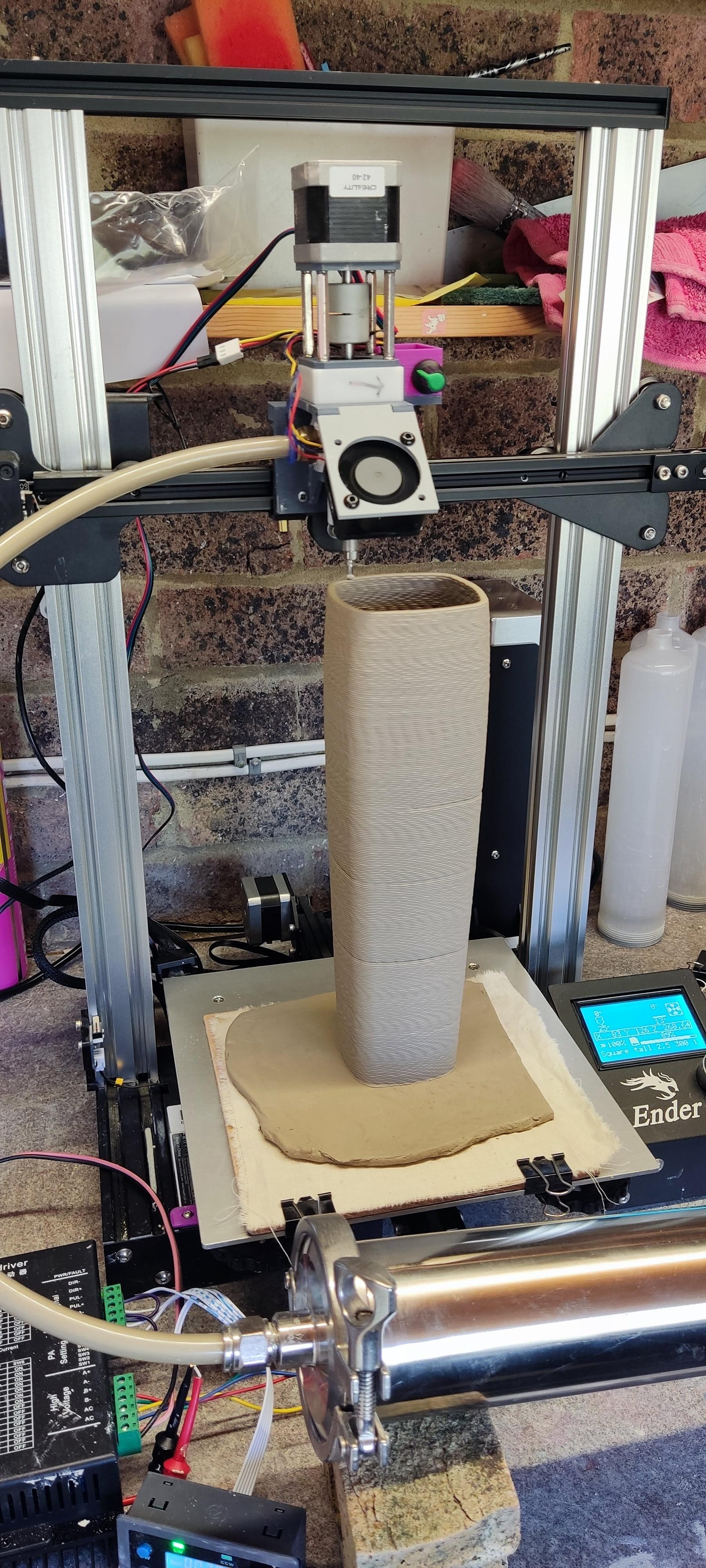
I have been using a Tronxy Moore 1 clay printer for some time quite successfully however I am quite limited by the size of the objects I can print. I wanted to get a larger build size, I am still limited by the height of my kiln around 350mm. The aim is to be able to print a height of around 390mm, the clay shrinks around 15% so that should give me a finished piece of around 330mm. Having looked at the off the shelf options and seeing that they are either very expensive or don't have great reviews I thought I would try converting my old Ender 3. It's a basic version with an 8 bit board.
I have set out in this Instructable how I have achieved this, I hope in enough detail as some often leave some details out
I have used the Tronxy Moore 1 extruder nozzle and printed a new bracket to fit the the Ender X gantry.
At the moment I am using the clay extruder from the Tronxy and using the Tronxy to control the extrusion rate, however I am planning to try a compressed air extruder and or upgrade the Tronxy extruder which I have now completed and the details are below.
Downloads
Supplies
Requirements for the conversion:
Access to a 3D printer to make the printed parts
An old Creality Ender 3 3D printer
All costs are rounded up to approximately what I paid at the time
Clay extruder nozzle:
Tronxy Moore 1 motorised nozzle. I used the one off my Tronxy Moore 1 printer but they can be purchased direct from Tronxy for around £60 which is quite expensive for what it is but I couldn't find a suitable alternative.
M5 threaded inserts and M5 bolts £2 https://www.aliexpress.com/item/1005003582355741.html
Nema 17 6 pin cable extender £1 https://www.aliexpress.com/item/1005006626672527
40mm Cooling Fan, 5V (PWM Adjustable) £3 https://www.unmannedtechshop.co.uk/
PWM controller (optional) £4
10 x 6.5 PU Pneumatic tubing £8
USB charger and cable (used one lying around)
Total around £80
For Installing the Firmware:
Arduino Uno or similar £4
Breadboard Cables
USB cable
Increase Z height:
Dual Z drive kit £23 https://www.aliexpress.com/item/1005006206958746.html
2 x T8 Lead screws for CR10 515mm long £10 https://creativity3dp.aliexpress.com/
2 x 540mm 2040 V Slot uprights with threaded both ends £23 https://ooznest.co.uk/
Total £56
Clay Reservoir/Extruder:
Tronxy Moore 1 clay extruder, again I used the one that came with my Tronxy Moore 1.
If you keep it connected to the Tronxy you can adjust the rate of clay extrusion via the menu, this worked quite well you just need to use trial and error to find a suitable rate for your print. Obviously this is dependant on the speed you print at and nozzle size.
However I have now upgraded this to give me a larger volume of clay. The costs below are for this upgrade as is the write up section below.
or
A barrel for holding the clay with 10mm push fit compressed air connections, 10 x 6.5 mm pneumatic pipe and connectors, on/off valve and regulator. Access to a compressor
I tried using the compressor and I failed to get consistent results and the air bypassed the piston
Large Clay Reservoir
Stainless steel sanitary pipe 500mm long with 77.5 flanges - £37 - Link
I have now purchased a smaller sanitary pipe 350mm long as I found I didn't need the larger volume
Pneumatic tube end 77.5mm - £13 - https://www.aliexpress.com/item/1005002416176430.html
Tube reducer 63mm to 77.5mm - £8 - https://www.aliexpress.com/item/1005006960706558.html
2 x Tri clamps and seals 77.5mm - £8 - https://www.aliexpress.com/item/1005002587707049.html
60mm Neoprene washers - £3
36v Power supply - £25 -
Nema 23 76mm 3.0A Stepper - £22 - https://www.aliexpress.com/item/1005005243592931.html
I found that the 76mm 3.0A stepper was missing steps occasionally and struggling to push the clay so I have changed this for a Nema 23 Bipolar Stepper Motor 1.8deg Φ8mm 3Nm 5A 57x100mm from STEPPERONLINE
DM860 Driver - £20 - https://www.aliexpress.com/item/1005007577381193.html
8mm to 14mm stepper motor adaptor - £3 - https://www.aliexpress.com/item/1005007058437414.html
SMC01 Stepper controller £8 - https://www.aliexpress.com/item/1005007245670036.html
M18 x 2.5 Threaded bar, M18 nuts and washers £16
I have increased the size of the PU tubing from 10x6mm to 12x8mm and changed the push fit adaptors for the nozzle and clay tank to suit.
Total around £165 compared to a Tronxy Moore 1 litre motorised extruder which is around £320 including tax from China. Or a Wasp kit which although bigger is over £850.
Dismantling Ender 3


Disconnect the Ender 3 from the mains supply.
Disconnect the cable to the extruder stepper motor
Remove the extruder motor and the filament clamp
Remove the hot end extruder and cover from the X gantry
Remove the cover to the controller board. Push the build plate to the back and remove the 2 screws to the cover plate, move the build plate the the front and remove the 3rd screw on the cover. Move the build plate to the rear and carefully lift the cover the fan will be connected to the controller board. Carefully remove the plug for the fan from the controller board, this is likely to be glued on so you may have to peel away the glue before carefully pulling it out, don't force it!
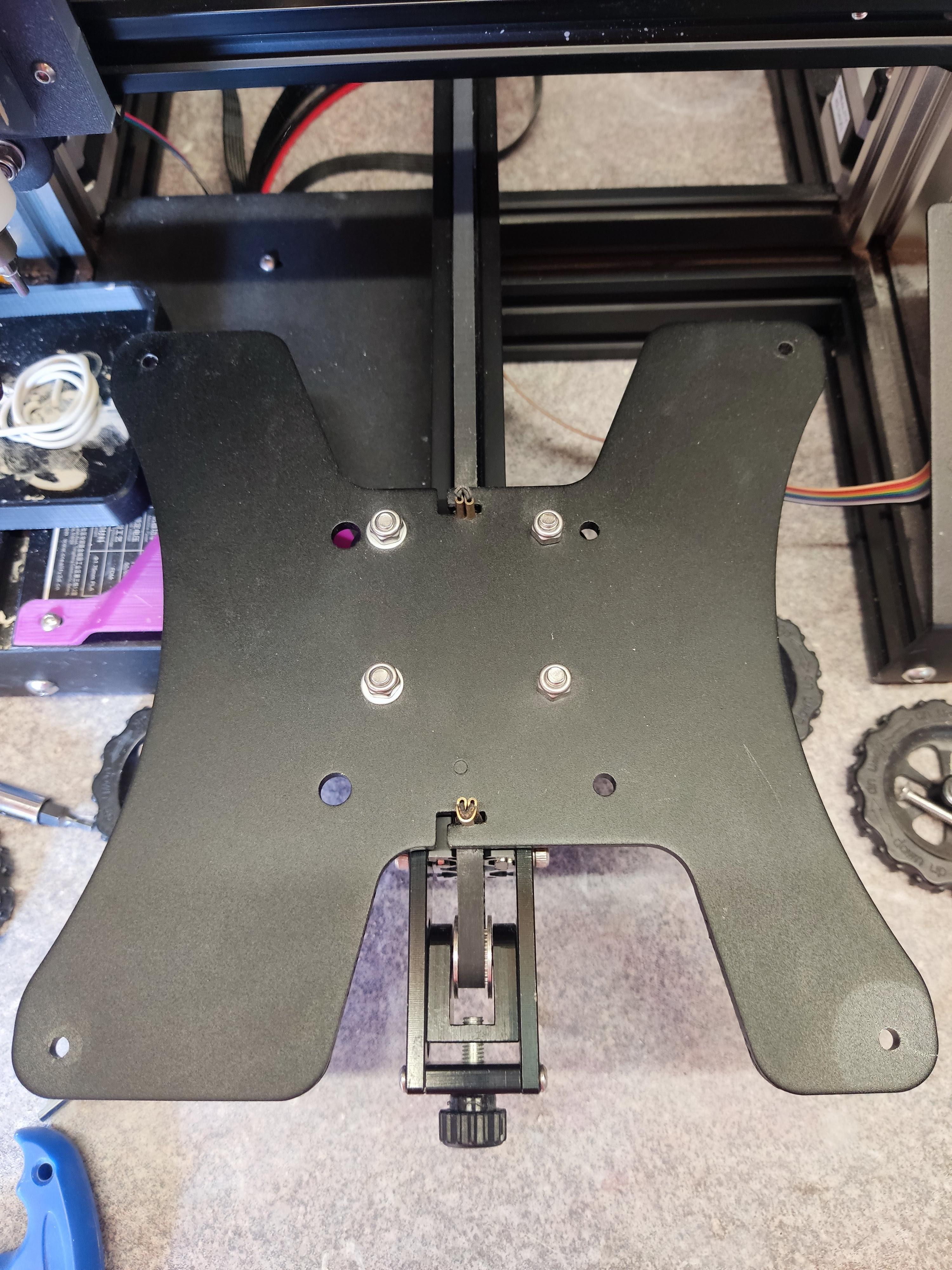
Remove the connections for the hot end, hot end fans and heated bed. See image above.
The cables are wrapped together with the other cables the tape where they enter the controller housing will need to be cut to remove them from the rear of the controller housing, use a cable tie to secure the remaining cables back together.
Cut the plug off the end of the cable for the controller fan fixed to the cover. Strip the wires and connect them to the controller board as shown in the second image. This will ensure that the fan is on when the printer is running.
Extruder Nozzle
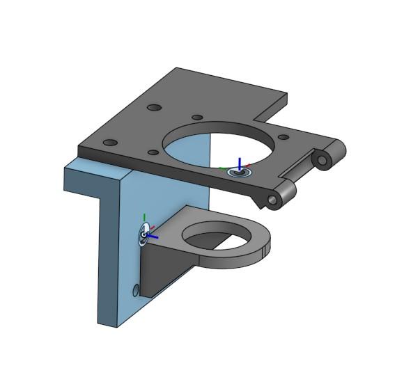
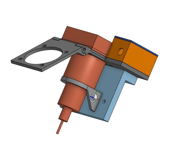


There are 4 parts to the extruder nozzle bracket.
The Gantry Plate which bolts onto the existing X gantry bracket once the hot end and fan have been removed. Use the same bolts that came off the hot end. The gantry plate needs brass M5 bolt inserts pushed in from the back I just used a soldering iron to heat them up and push into the hole, they need to be pushed vertically. They usually squeeze some plastic around where the bolt is inserted so this needs to be cleaned up.
The Bottom Bracket which accepts and supports the Tronxy Moore nozzle. The bracket is inserted into the Gantry Plate, it is a tight fit so may need to be filed down to remove any edges from the printing, it can also be superglued in if required.
The Hinged Top Plate which is bolted to the Gantry Plate and accepts the Tronxy Moore nozzle, it also has half the hinge which to which the fan is mounted and a side plate on which the fan controller can be fixed.
All the STL model files are available below.
I'm not entirely clear why but the NEMA 17 stepper attached to the Tronxy nozzle did not work when connected to the Ender 3 extruder cable. So I swapped it for the original stepper from the Ender 3 however the spindle is slightly longer and so when the auger is attached it touches the bottom of the auger casing. To resolve this a couple of 3D printed spacers (Nema 17 spacer-chamfer.stl) and washers are required between the stepper and auger. See photos
Use a extension cable to connect between the ender 3 extruder motor cable any the Tronxy nozzle motor
The Lower Hinge section is attached to the Hinge Top Plate with a 3mm diameter section of plain steel rod or you could use a long 3mm bolt.
I used a 40mm Cooling Fan, 5V (PWM Adjustable) which is bolted to the underside of the Lower Hinge unit this is connected to a PWM controller and powered by a standard 5V USB charger. This provides a constant airflow over the work as is is printed, I have found that this helps to stiffen the clay making it less likely to collapse during the print.
The Switch Box and Top are to house the PWM fan controller, the box is superglued to the Hinge Top Plate and the top can be glued on once the controller is fitted.
Firmware


My Ender 3 is an early version with the 8 bit V1.1.4 board and the most suitable firmware upgrade I could find was that by TH3D. Link to their site below which gives detailed instructions on installing the firmware including a YouTube video.
TH3D site here note this is discontinued firmware version
One thing to note however is that I found that the process for uploading the bootloader is best explained and worked for me on this YouTube video here.
This video I found best for details of how to edit and upload the firmware here it does also include details on uploading the bootloader but I couldn't get it to work so used the video above.
I made the following changes to the Firmware using the Visual Studio programme.
The only file that needs to be edited is Configuration.h the images in this section are screenshots of the changes made.
The version of the Configuration.h file should be as below
#define CONFIGURATION_H_VERSION 02010200
Check that the correct printer is uncommented line 26
#define ENDER3
I changed the custom extruder steps for the Tronxy Nozzel to 1440, this is around line 140.
#define CUSTOM_ESTEPS
#define CUSTOM_ESTEPS_VALUE 1440
however this can also be changed in the custom start G-code in Cura using this line
M92 E1440 ; Set extruder steps to 1440
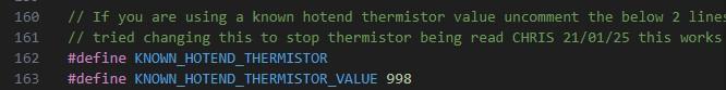
When you remove the Thermistor connection to the hot end from the board, the printer will be looking for the correct temperature to be achieved before it starts to print, as it has been disconnected it will give an error and not print. To overcome this make the following change in the code, this will then make the temperature always read as 10 deg C. This is around line 162
#define KNOWN_HOTEND_THERMISTOR
#define KNOWN_HOTEND_THERMISTOR_VALUE 998
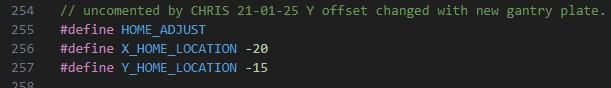
I changed the X and Y home location to account for the offset of the gantry plate and Tronxy Nozzel around line 255
#define HOME_ADJUST
#define X_HOME_LOCATION -20
#define Y_HOME_LOCATION -15
I have increased the Z height of the printer by adding longer upright sections and Z screws, also adding dual Z screws. Once done uncomment and change the Z height in the code at around line 207 as shown below
// Bed and Z Height Adjustments
// If you need to make changes to your X, Y, and/or Z size on your printer for whatever reason you can uncomment the custom size/height line
// for whatever axis you need to make changes to and then replace the XXX with the new size in millimeters.
//#define CUSTOM_X_BED_SIZE XXX
//#define CUSTOM_Y_BED_SIZE XXX
#define CUSTOM_Z_HEIGHT 390
These are the only changes needed in the firmware, once completed follow the instructions in the video to upload the code to the printer.
Printing With Cura
I use Cura to slice my models using the spiralize vase mode.
There are a lot of settings so I have placed some images of the settings I use.
I print directly onto a 5mm thick rolled out slab of clay, in order to do this I offset the Z axis by 5mm, this requires a extension download from Marketplace in Cura. This is called Z Offset Setting
I also use the post processing script Remove Spirialize Top this stops the last layer of the print being smoothed as I found that on some prints the pressure of the print nozzle would push the vase out of shape or squeeze the clay so that the previous layers were squashed.
I have updated the start and end G-Code as set out below
Start G-Code
G28 ;Home
M302 S0 ; Always allow extrusion no temp check
M92 E1440 ; Set extruder steps to 1440
G1 Z15.0 F6000 ;Move the platform down 15mm
;Prime the extruder
G92 E0 ; Set extruder position
G1 F200 E3 ; Extrude small amount of filament
G92 E0 ; Set extruder position
End G-Code
M104 S0 ; Set hot end temp to 0
M140 S0 ; Set bed temp to 0
G91 ;set to relative coord
G1 Z5 F300 ; Move nozzle up 5mm
G90 ; Set to absolute coord
G28 X0 ; Move nozzle to X home
M18 ; Disable all steppers
Before starting a print I extrude the clay through the tube and into the nozzle, once the clay reaches the nozzle connector I start the nozzle stepper through the firmware on the Ender. In the menu go to Motion>Extruder you will get a warning that the hot end is too cold just proceed on this. Select 10mm then rotate the selector to start the nozzle stepper, rotate until the clay is extruding at a constant rate from the nozzle. Once ready turn off the clay extruder as you don't want to be building up pressure in the clay.
I have created a copy of my Cura Profile which can be downloaded from here Link you may need to tweak it for your use. This is for a 2.5mm nozzle and 1mm layers, it includes a 5mm offset from the base plate, however this will only work if you install the add on.
Fan Protection and Drip Tray

The fan cooling the board is exposed to any clay dust and particles falling into the controller housing. I have therefore printed a cover to protect it.
The cover was designed by Dinesh and can be downloaded from Thingiverse here
When preparing for printing it is necessary to prime the print head with clay this can be messy as the clay is extruded onto the the box holding the board, so I have designed a drip trap to catch the clay.
Downloads
Increasing Z Height
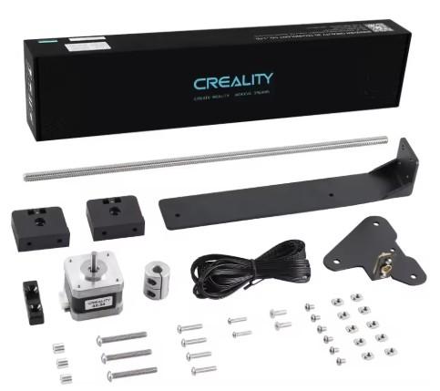
The first thing I did was to convert the Ender to dual Z lead screws. The kit is readily available on AliExpress and other outlets. Mine cost about £23 from AliExpress. Instructions are fairly basic but it is a fairly simple task.
The Z axis cable is replaced with one supplied that connects to both Z axis stepper motors.
I purchased 2 longer T8 lead screws meant for the CR10 which are 515mm long and 2040 V Slot uprights which are 540mm long, these should be ordered with both ends threaded. This is a simple replacement of the standard uprights.
These modifications will give a new potential Z print height of 390mm
Note the firmware update required if the Z height is changed
The cable to the nozzle stepper will need to be extended.
Clay Reservoir/Extruder - Mechanics


Having increased the print size the clay reservoir from the Tronxy is only 500cc therefore to enable me to print larger pieces without changing the reservoir part way through a print I needed a larger clay volume.
Off the shelf options were quite expensive so I thought I would try and design and make my own. I referred to the design by Bryan Cera here as a starting point.
I tried to source a gearbox similar to the Tronxy Moore which has a threaded output shaft but I could not find anyone selling them, therefore I resorted to using my Tronxy gearbox.
I have since contracted Tronxy to see if I could purchase a threaded gearbox from them which they initially offered to do. I placed an order and waited a couple of weeks after which they told me they had none in stock and refunded me. A bit frustrating but typical of my experience with Tronxy.
I used a stainless steel tri clamp sanitary pipe 500mm long with 77.5mm flange, the internal diameter is 60mm. This gives a total volume of around 1400cc although that is reduced by the size of the plunger. The output end has a cap with a push fit pneumatic connector. I ordered one for a 10mm pipe but I am now looking to change the pneumatic connector to one for a 12mm pipe. This has now been upgraded and works much better.
The pipe is connected to the gearbox using a stainless steel tri clamp reducer 77.5 to 63mm, to connect it to the gearbox I filed cut-outs to accommodate the bolts, I printed a template to get the exact locations and size of the cut-outs. The STL file for the Adapter Hole Template is attached.
The threaded rod is an M18 x 2.5 I purchased a 1m rod which I then cut to size, this is hardened steel so a hacksaw wouldn't cut it I had to use an angle grinder with a cutting disc.
To make the rod protrude from the gearbox when it is running the rod has to be prevented from turning, to do this I braised a nut to the end and then ground it down to a square shape with an angle grinder. This then passes through a square steel tube mounted to the opposite side of the gearbox, I used a piece of old steel square table leg. The tube is fixed to the gearbox using a 3D printed part. The Tube Support STL files attached, I printed these as solid for strength. One part has some M5 brass threaded inserts, which I melted into the part with a soldering iron. I also left 2 holes to enable me to add 3mm spigots to the tube to prevent it pushing out of the mount, however so far these haven't been required.
The piston is printed in 2 parts so an M18 and M8 nut can be placed inside and then superglued together. The main rod screws into the M18 nut. I then bolted a 60mm Neoprene washer to the end using an M8 nut and steel washer. The Washer Plunger STL files attached.
Clay Reservoir/Extruder - Electronics


I replaced the original Tronxy stepper with a larger 76mm 3.0A version in the hope this will be powerful enough.
I found that the 76mm 3.0A stepper was missing steps occasionally and struggling to push the clay so I have changed this for a Nema 23 Bipolar Stepper Motor 1.8deg Φ8mm 3Nm 5A 57x100mm from STEPPERONLINE
The stepper is driven with a DH860 microstepper and SMC01 controller. The stepper driver is powered with a 36V supply.
I originally tried controlling the stepper with a Arduino Uno and a rotary encoder to adjust the speed, but I found this to be unreliable and there was no way of knowing what speed the stepper was running.
A SMC01 controller is much more versatile allowing you to adjust the step frequency and adjust the RPM of the stepper on the fly and also switch between clockwise and anti-clockwise.
This is a pretty good explanation of the wiring on YouTube Link
Knowing the speed of the stepper allows me to find and replicate appropriate speeds for the various sized nozzles and layer thicknesses I am printing.
Using the new 100mm stepper motor I have set the DH860 to
Build Plate
this is a build plate
jgdhgjgjdg
Conclusion
I have had fun with this project I hope you find it useful.
I'm happy to answer questions if I can, there maybe aspects that need more explanation.
Happy printing!