Exercise Machine USB Game Controller
8427 Views, 26 Favorites, 0 Comments
Exercise Machine USB Game Controller


To encourage exercise in self and family, I made an adapter that emulates a standard USB game controller adapter but controls game movement speed by pedalling on an elliptical machine or exercise bike. It's particularly nice for racing games. It certainly motivates one to pedal fast when playing racing games.
The main hardware is a $2 "black pill" STM32F103C8 development board with the stm32duino Arduino core and a USB HID library I developed based on libarra111's core fork. The STM32F1 is fast and cheap and has full-speed USB support, so it's perfect for the project.
To use, you need to tap into the rotation sensor on the elliptical or exercise bike (if your rotation sensor works differently from the ones on our machines--about 3v, active low--you may need to modify the circuit and/or code).
The elliptical/bike rotation speed controls the controller slider. Additionally, you plug a standard Wii Nunchuck or Gamecube controller into the adapter for joystick movement, buttons, etc. There are a lot of different control modes. For instance, smaller kids may need to have their speed boosted a little, and some games may use a different control scheme. There are a number of built-in control schemes in the software, and others can easily be added in the code. The device can emulate a USB game controller, keyboard, mouse, XBox 360 controller, or some combination of the first three.
Direction of motion is currently not detected: to switch between forward and reverse motion, the adapter has a toggle switch. (Alternately, one could use a hall-effect magnetic sensor like this device, and change the circuit and software.)
The adapter works as a standard USB controller, so you can use it with Windows, Linux, OS X, Android, etc.
As a bonus, the adapter has all the functions of this project, working as a full-function Gamecube adapter, letting you use Gamecube controllers on a computer, including controlling games with Gamecube/Wii compatible Dance Dance Revolution dance mats.
The cost is under around $10, plus case (I have a 3D printable design), wires and solder. Parts:
- "Black Pill" stm32f103c8 development board ($2 on Aliexpress)
- Gamecube socket ($1.60 on Aliexpress, for a Gamecube extension cord that can be cut down)
- Nunchuck socket breakout board ($0.51 on Aliexpress; search for Wiichuck)
- Small two-position toggle switch (under $1 on Aliexpress)
- Your choice of two-conductor male and female connectors (about $1 on Aliexpress if you go with 5.5mm power barrel connectors); you need one female connector per exercise machine
- 2 tactile switches (under $0.50 on Aliexpress)
- 4 red LEDs (under $0.50 on Aliexpress; you could also use a small Nokia LCD screen)
- capacitors: 10uF electrolytic, and optional 100nF
- resistors: 1 x 100K, 2 x 10K, 1 x 1K, 4 x 220ohm
- small proto board (under $1 on Aliexpress).
A Nunchuck is good for one-handed use with an elliptical machine. On an exercise bike, you can use a two-handed adapter like the Gamecube one. If you only want to use one of these two control options, you can use fewer connections.
You also need a computer, a soldering iron, and a multimeter. You will also need a UART-to-USB bridge (I used an Arduino Mega that I had for another project; or you can buy a CP2102 module on Aliexpress for a dollar) to install a bootloader on your black pill to use it with the Arduino environment, or else you can spend a couple more dollars and get RobotDyn's development board with an Arduino bootloader preloaded.
Let me add that I am entering this into the Wheels contest, because it is a way of linking the virtual wheels in car racing games on a computer with the physical wheels of exercise bikes and ellipticals.
Tap Into Rotation Sensor


Both of the exercise machines I hacked have a console that displays the speed. There are wires running between the console and the body of the machine. You need to tap into these wires to access data. If your machines are like mine, the console can be removed, and you there find either a ribbon cable (elliptical) or two wires (bike). I tapped into these by disconnecting the wires and bridging them with individual male-to-female jumpers that I could tap into.
Use trial and error and a multimeter to identify a pair of wires between which has a voltage pulse during a full rotation.
Basically, the drill is this: hook up the multimeter to a pair of wires (being careful not to short anything) with the machine running, and very slowly rotate the pedals. In both of our machines, there is a pair of wires between which normally the voltage is around +3V, but during a short portion of the rotation it falls to ground: this is an active-low scheme. You might find your machine has an active-high scheme where most of the rotation is ground, and the pulse is positive, and then you'll need to edit the Arduino sketch.
If you think there is any chance that any of the wires into the console you're dealing with are mains AC, I recommend stopping unless you really know what you are doing. Fortunately, our exercise bike is battery powered and our elliptical plugs into a wall wart so there is only about 12V DC around the console.
In the case of the exercise bike, it was really easy. There were only four wires. Two were for the heart-rate monitor and two were for rotation sensor.
The elliptical had a lot more wires, and so it was more work. The brute-force method is this. Attach a multimeter to a pair of wires. Slowly do a full rotation (or a bit more just in case) on the pedals and see if there is a voltage dip or jump. If yes, you've got it. If not, repeat for another pair. That's a lot of trial and error: for 13 wires, it's 78 rotations.
Here is a trick that might help you to speed up the search for the right wire pair. You might hope that your machine, like mine, has the detector voltage normally high with a low pulse. If so, then if you leave the pedals at a random location, you've got a good chance that the two detector wires have around +3V or +5V between them. So only do the pedal rotation test for those pairs of wires that have +3V or +5V between them.
Another trick. You might be able to identify where in the pedal rotation the rotation sensor triggers. For instance, your machine might flash something on the screen then, or update the speed display, or activate from sleep mode, or beep. If so, then move the pedals about 1/3 of a rotation away, and then look for pairs of wires that have 3-5V between them, and test those by moving the pedals to the position where the sensor triggers.
If you can identify the ground wire, you can speed up the process considerably, since you then only need to go between ground and each unknown wire. Oddly, though, on our elliptical the power supply's ground didn't seem to be the same as the rotation detector's ground.
Once you identify the wires, make a note of them. Make sure you note:
- the high voltage level: if it's more than about 3.3V but no more than 5V, you'll want to change the circuit to use pin A9 instead of A7 for rotation detection as pin A9 is 5V-tolerance and A7 is not, and edit one line in my sketch; if it's more than 5V, you'll need to add a voltage divider
- whether the rotation detection pulse is low or high: if the pulse is high, you'll need to edit a line in my Arduino sketch.
If you have an oscilloscope, and the exercise machine is battery powered, you can also use the oscilloscope instead of the multimeter. (If the exercise machine is plugged into AC and so is your oscilloscope, you need to know about ground loops and how to avoid them. Be careful!)
Prepare Development Board


Solder the six central jumper pins onto your black pill.
If you have a RobotDyn board with the Arduino bootloader, connect B0- and B1- to the center pins, and you're done with the step.
Otherwise, you now need to install the bootloader. You'll need either a standalone UART to USB bridge or you can use an Arduino Uno or Mega for this purpose. Although the black pill runs at 3.3V, the UART pins are 5V tolerant, so don't worry about whether your connector runs at 3.3V or 5V.
If you have an Uno or Mega, put a jumper cable between RESET and GROUND. This turns the Arduino into a dedicated UART to USB bridge, except that the TX/RX pins are the reverse of how they usually are on a connector.
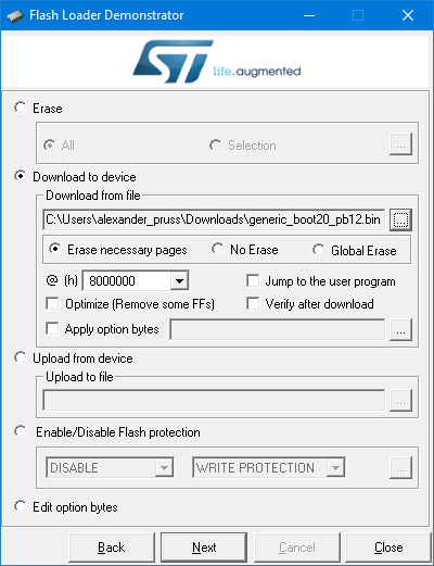
Download the bootloader binary. You want generic_boot20_pb12.bin. On Windows, install ST's Flash Loader Demonstrator. On Linux (and maybe OS X and even Windows if you prefer commandline tools), use this python script instead, but my instructions will be for Windows.
Make the following connections:
- PA9 to UART bridge RX ("TX" if you're using the Arduino trick)
- PA10 to UART bridge TX ("RX" if you're using the Arduino trick)
- G to UART bridge ground
I like to use logic probe tips to make the connections on the STM32 side, but you could also just solder in some wires that you can later cut off (or de-solder if you want to be neat).
Connect your UART bridge to your computer. Power up the Black Pill via its USB port (best if you connect it to a charger rather than the computer, as the computer will likely complain about an unrecognized USB device). Start the Flash Loader Demonstrator. Choose the COM port for your UART bridge. Choose "Remove protection" if available. Choose a 64kb rather than 128kb flash version. And upload the bootloader binary.
Unpower everything and then move the jumper from B0+/center to B0-/center. You now have a bootloader that you can use with the Arduino IDE.
Prepare Stm32duino in Arduino IDE


I assume you have the latest Arduino IDE installed.
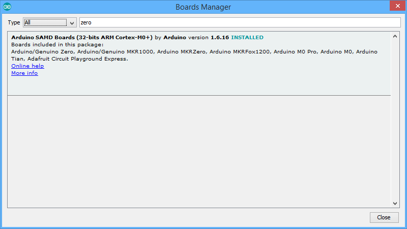
In Tools | Boards | Boards Manager, install support for the Arduino Zero (just put Zero in the search, click on the found entry, and then Install). Yes, you aren't working with a Zero, but this will install the right gcc compiler.
Next, download the stm32duino core. On Windows, I recommend downloading the zip file, since when I checked out the files (admittedly, with svn), I had some permissions problems with files in the Windows tools directory that needed fixing. Put the branch in Arduino/Hardware/Arduino_STM32 (so you'll have folders like Arduino/Hardware/Arduino_STM32/STM32F1, etc.) On Windows, install drivers by running drivers\win\install_drivers.bat.
Install my USBHID library: Go to Sketch | Include Library | Manage Libraries, and search for USBHID. Click on it and click on Install.
Install my GameControllersSTM32 library: Go to Sketch | Include Library | Manage Libraries, and search for GameControllers. Click on it and click on Install.
Circuit


My setup uses four LEDs to indicate the current emulation mode in binary (yes, one could use an LCD display, but I had LEDs lying around when I built this), two push-buttons to switch mode up and down (and do some other tricks), and a toggle switch for switching movement direction.
Additionally, there is an I2C input from the Nunchuck and a connector to the Gamecube controller. If you want to support only one of these two, you can just edit gamecube.h in the sketch and save yourself some soldering.
I used a small bit of protoboard to mount the four mode LEDs and two mode-switch buttons (up and down), as well as the one pull-up resistor for Gamecube data. I brought out 3.3V to the protoboard, but I didn't need to bring out ground to it, though you can if you like. I used another small bit of protoboard to mount the Nunchuck connector.
Cut the Gamecube cable. You want to work with the socket side, the one that your controller will plug into. Strip cables for connecting.
Now make these connections as per the circuit diagram:
- 10uF capacitor between 3.3v and ground (with the minus side of any electrolytics at ground). This should be as close to the chip as possible, so I soldered it right on the development board rather than the protoboard. For good measure, you can add a 100nF as I did, but I am not sure that's needed.
- Gamecube socket #2 -- A6 on stm32 board
- 1Kohm resistor between Gamecube socket #2 and 3.3V on stm32 board (or on protoboard)
- Gamecube socket #3 and #4 -- ground on stm32 board
- Gamecube socket #6 -- 3.3V on stm32 board (or on protoboard)
- LED in series with 220ohm (or bigger) resistor between A0 on stm32 board and 3.3V (negative end (flat) to PA0; positive end to 3.3V)
- Repeat with LED+resistor between A1 and 3.3V, A2 and 3.3V, and A3 and 3.3V
- Momentary switch between A5 on stm32 board (increment mode) and 3.3V and another between A4 and 3.3V (decrement mode); this switch increments the mode number
- Toggle switch between A8 and 3.3V
- exercise machine ground -- stm32 ground
- exercise machine positive signal -- stm32 board A7 (note that A7 is only good for 3.3V; if your exercise machine is 5V, use A9, and edit gamecube.h)
- Nunchuck ground (labeled - on my adapter board) -- stm32 ground
- Nunchuck +3.3V (labeled +) -- stm32 3.3V
- Nunchuck SDA (labeled D) -- stm32 B7
- Nunchuck SCL (labeled C) -- stm32 B6
- 10Kohm resistor between Nunchuck SDA and 3.3V on stm32 board
- 10Kohm resistor between Nunchuck SCL and 3.3V on stm32 board.
Install Sketch


Download my Gamecube USB Adapter sketch and load it into the Arduino IDE. There are some options to control in gamecubecontroller.h:
- remove // in front of #define ENABLE_EXERCISE_MACHINE (everyone needs to do this one)
- if you needed to move the exercise machine connection to A9, change PA7 to PA9 in the const uint32_t rotationDetector = PA7 line
- if your exercise machine rotation detection pulse is high, change #define ROTATION_DETECTOR_CHANGE_TO_MONITOR FALLING to #define ROTATION_DETECTOR_CHANGE_TO_MONITOR RISING
- if you don't want to use a Nunchuck, put // in front of #define ENABLE_NUNCHUCK
- if you don't want to use a Gamecube controller, put // in front of #define ENABLE_GAMECUBE.
In the Arduino IDE, choose Tools | Board | Generic STM32F103C series.
Press the right-arrow upload button. Note that you may need to press the reset button (or unplug/plug) the board at the right time in if you get a message that the board is not recognized.
Exercise Machine Connection


Splice in a jack for your exercise machine connection. On our elliptical machine, I soldered it in, while on the exercise bike, I was able to use male and female dupont connectors. On the elliptical, I made a hole in the side of the console to fit the connection. On the exercise machine, I just have wires sticking out of it, and a little 3D printed box (OpenSCAD file) on the outside.
Project Case


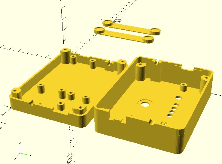
One can enclose the project in a small cardboard box, a tupperware container, or a custom 3D printed enclosure. Since I have a 3D printer, I went for the custom enclosure. The OpenSCAD and STL files are here.
The feet are designed to glue (superglue works) to the bottom, and to have sticky rubber feet stuck into them.
I also hot-glued some hook-and-loop fastener to both the project case and the exercise machines.
Use


The two buttons can switch between up to 16 different emulation modes (you can have more, actually, but there are only four LEDs in the project to display the mode number). The emulation modes are defined in gamecubecontroller.h in the sketch. For most games, you can use mode 1, unified slider joystick at 100% speed. The emulated joystick has a slider (actually two sliders, but both do the same thing) that is controlled by the exercise machine rotation. The buttons and joystick itself are controlled by the Gamecube controller or Nunchuck. On Windows, some games support an XBox 360 controller but not a USB Joystick. For those, use mode 13 (press the down button from mode 1).
Modes 9 and 10 allow you to pedal slower and still get full slider depression, which is nice for children, or for exercise machines set to higher resistance. You can also adjust the speeds in exercisemachine.ino.
There are many other emulation modes. A printable reference is included in modelist.pdf with the sketch.
When you pedal on the exercise machine, the LEDs on the project switch from displaying the current mode number to the speed. When all four lights are lit, your speed is at maximum (the emulated slider has maximum extension)--at that point, you get no in-game advantage from going any faster. Additionally, the blue LED on the STM32F1 board is on when everything works, but blinks off when the rotation sensor triggers.
To reverse movement, flip the direction toggle switch on the adapter box.
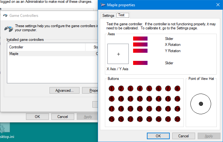
On Windows, run joy.cpl to calibrate and see how things work. Because it's a nuisance to have to pedal really fast to calibrate the emulated joystick, there is a way to cheat for calibration. On the Gamecube controller, if you stay still for about 10 seconds, you can start using the shoulder buttons to control the emulated joystick sliders. With the Nunchuck, while you hold the mode-minus button, you can use the joystick up/down to control the emulated sliders instead.
If you want a GUI for switching emulation modes, on Windows the sketch includes mode.py, a python script with a GUI for switching modes. You can also invoke mode.py in a batch file that launches a game.
Two games that I have found to work really great with the exercise machine are Toybox Turbos and SuperTuxCart (free).
The adapter also includes a lot of other emulation features. For instance, you can use it as a straightforward Nunchuck or Gamecube Controller adapter, emulating joystick, keyboard (e.g., arrows/WASD) and/or mouse. There are a lot of modes listed in gamecubecontroller.h. You can also plug a Dance Dance Revolution Gamecube/Wii-compatible pad, and use that to play games not designed for it, like Tetris, for additional fun and exercise.