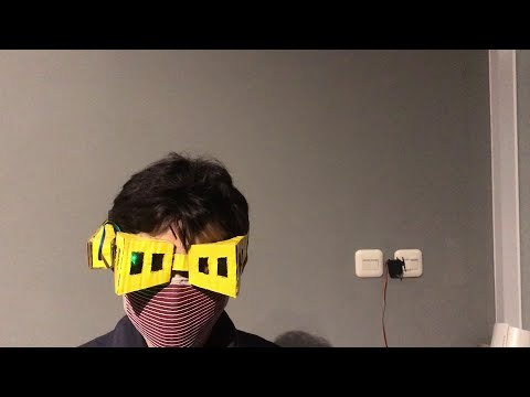
Eye-Blink Controlled Light Switch Using Shota Aizawa's Eraser Head Goggles (My Hero Academia)
by Barqunics in Circuits > Arduino
2772 Views, 6 Favorites, 0 Comments
Eye-Blink Controlled Light Switch Using Shota Aizawa's Eraser Head Goggles (My Hero Academia)

.JPG)
)
If you read my hero academia manga or watch my hero academia anime, you must know a charracter named shota aizawa. Shota Aizawa also known as the Eraser Head, is a Pro Hero and the homeroom teacher of U.A.'s Class 1-A. Shota's Quirk gives him the ability to nullify another person's Quirk by looking at the user. His ability deactivates if Shota blinks or if his line of sight is obstructed. Eraser Head can be recognized by the yellow goggles he wears around his neck, hidden by his scarf. He only puts them on in a fight because they complement Shota's Quirk.
I was inspired from this charracter and I wanted to control the appliance such as lamp in my home with eye blink. This approach of controlling appliance(Lamp) with eye blink would be especially useful for a wide range of people, starting with those who are almost completely paralyzed to completely healthy persons.
Hardware and Materials Used
Arduino Uno : https://amzn.to/2qU18sO
II https://sea.banggood.com/custlink/KKmEYs7I9O
Arduino nano: https://amzn.to/2zMXJU8
|| https://sea.banggood.com/custlink/DGKYYswZIE
9v battery: https://amzn.to/2wPmnSP
|| https://sea.banggood.com/custlink/KmKYdQw8Ii
Switch: https://amzn.to/2upTngE
|| https://sea.banggood.com/custlink/mG3yyNT8Oi
Jumper wires: https://amzn.to/398mQhq
|| https://sea.banggood.com/custlink/vK3hds7SAZ
Male DC Barrel Jack Adapter for Arduino : https://amzn.to/2VwyKxx
|| https://sea.banggood.com/custlink/K3DhRNwSlL
MG955 Servo Motor: https://amzn.to/2yutQYL
|| https://sea.banggood.com/custlink/mmmEysuZso
Mini Breadboard : https://amzn.to/2JujS9e
|| https://sea.banggood.com/custlink/D3KhynuiIq
9v Battery Clip Connector : https://amzn.to/32D4R
|| https://sea.banggood.com/custlink/mvDdYsw98s
Cardboard : https://amzn.to/39ufbKH
IR Sensor Module : https://amzn.to/3c6rePx
|| https://sea.banggood.com/custlink/vKvyEbu9Ag
NRF24L01+ 2.4GHz Wireless RF Transceiver Module: https://amzn.to/30xQlp4
|| https://sea.banggood.com/custlink/DmGEEnw9i4
AC 100-240V to DC 5V 2A Power Supply Adapter : https://amzn.to/387pTGV
|| https://sea.banggood.com/custlink/3GmhyQw6VZ
Velco Strap : https://amzn.to/2BPpEE5
Hot Glue Gun : https://amzn.to/31sIko3
|| https://sea.banggood.com/custlink/GmvhYQ1ome
Soldering Iron Kit : https://amzn.to/3eHmp0i
Making Eraser Head Goggles From Cardboard


- Lay out the cut-outs as shown in the picture
- Assembling with hot glue
- Paint the goggles with a yellow spraycan
- Let it dray
Wiring Diagram for Transmitter (Eraser Head Goggles)


The following image shows the complete wiring diagram of transmitter using Arduino Nano. After connecting all components then I inserted all these components into the enclosure and sealed it completely using hotglue.
The Ir sensor detects the blink to switch ON the lamp and if the ir sensor detects the blink again the switch will OFF. NRF24L01 2.4 GHz Transceiver Module can be used for wireless communications at up to 100 meters.The operating voltage of the module is from 1.9 to 3.6V, but the good thing is that the other pins tolerate 5V logic. The module communicates using SPI protocol. You should make looking at the arduino pin connector model SPI pins.
Transmitter (Eraser Head Goggles) Code
You need to do is install RF24 Library. You will get an error if you dont install.
When you want to add a new library into your Arduino IDE. Go to the directory where you have downloaded the ZIP file of the library. Extract the ZIP file with all its folder structure in a temporary folder, then select the main folder, that should have the library name. Copy it in the “libraries” folder inside your sketchbook. Connect the arduino nano and upload the given program on your arduino nano.
Wiring Diagram for Receiver


When moving a servo motor with Arduino, as with other motors, it is almost impossible to draw voltage or current from Arduino. In this case, you can take the external power supply and transmit angle control signals only from Arduino to control the servo motor.
For example, Arduino UNO R3, has I/O pins (digital/analog pins) that draw approximately 20mA from each individual pin (with possibility of damage if 40 mA+). Even though the operating voltage of the servo motor is 5V, since the power supply from the digital/analog pin is insufficient in electric current, the servo motor and Arduino can be damaged. In the case of a MG995 servo motor with an operating voltage of 5-7 V, it’s necessary to supply power to the servo motor separately from Arduino as shown in the circuit diagram below.
Receiver Code
Connect arduino the PC using USB cable and upload the given program on your arduino uno.
Setting Up the Servo


I used a double tape to attach the device to the light switch. When you are done, test to see if the servo motor works correctly and it turns on/off the light
Finish

Does it work? Good! I hope you enjoyed this Arduino project and learned something new. You can subscribe my channel for the support.
Thank You.