File-Centric Pico 2 Touch LCD Macro Pad + Modular I2C Bus
by Tobiasv6 in Circuits > Electronics
47 Views, 0 Favorites, 0 Comments
File-Centric Pico 2 Touch LCD Macro Pad + Modular I2C Bus
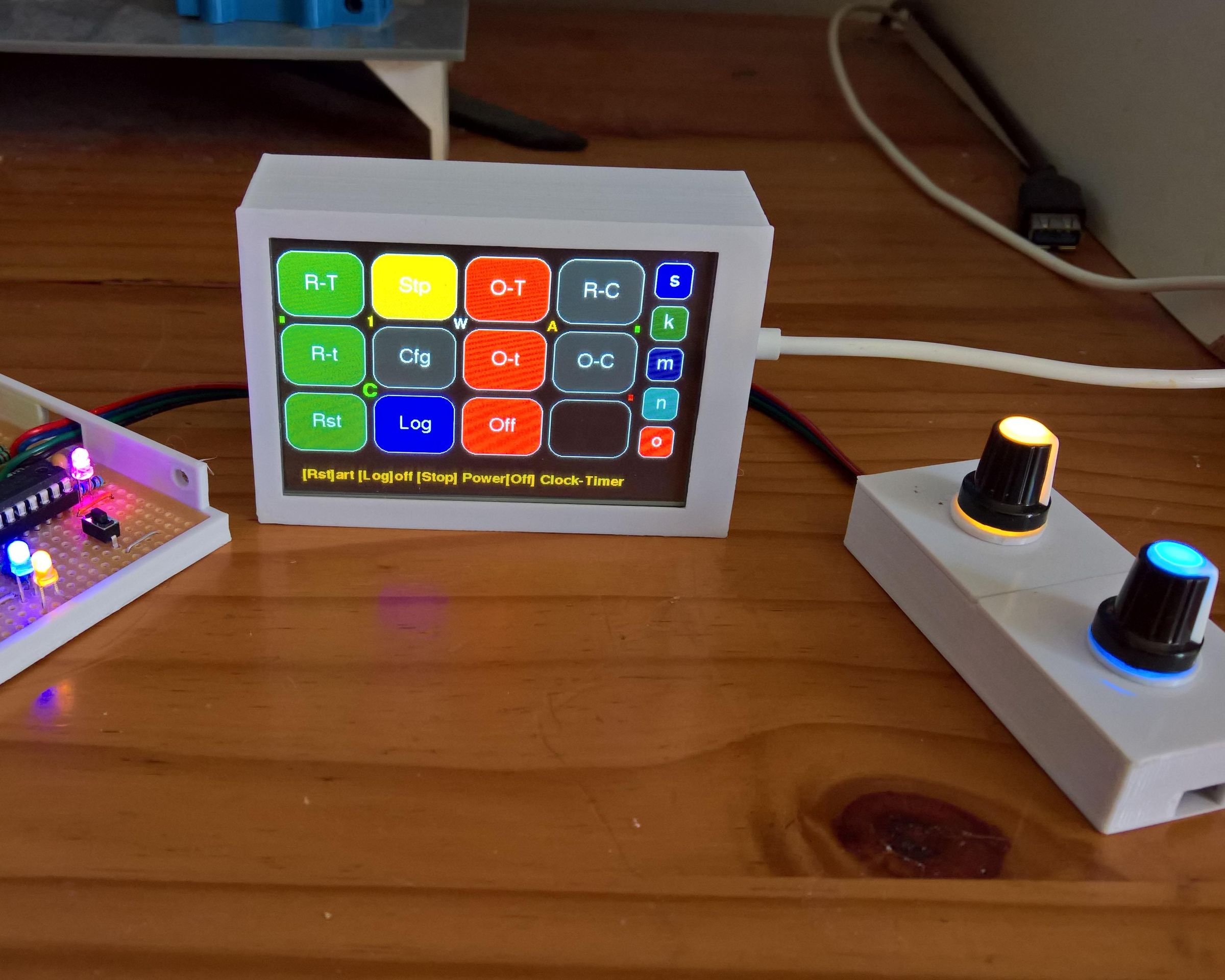
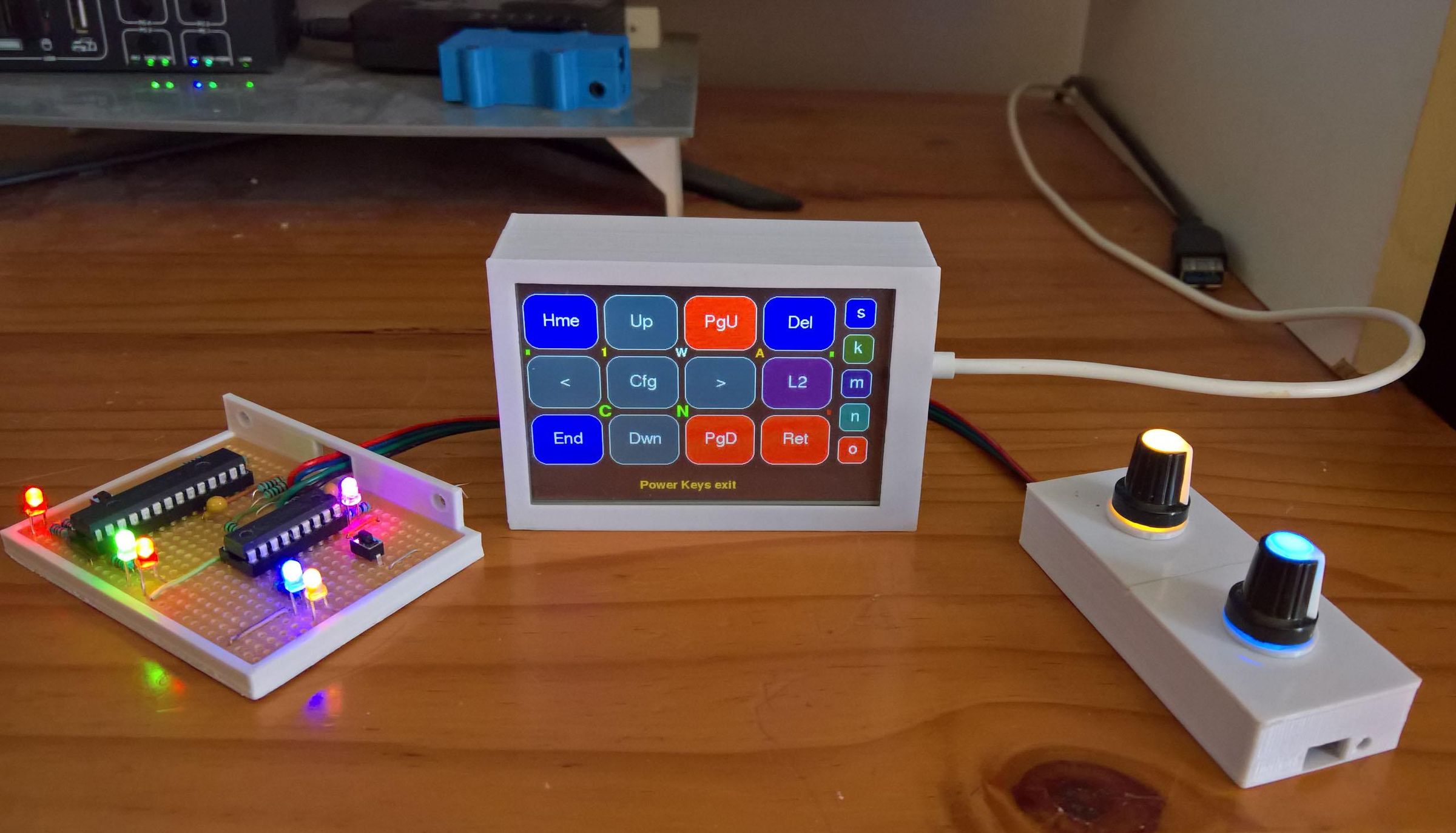
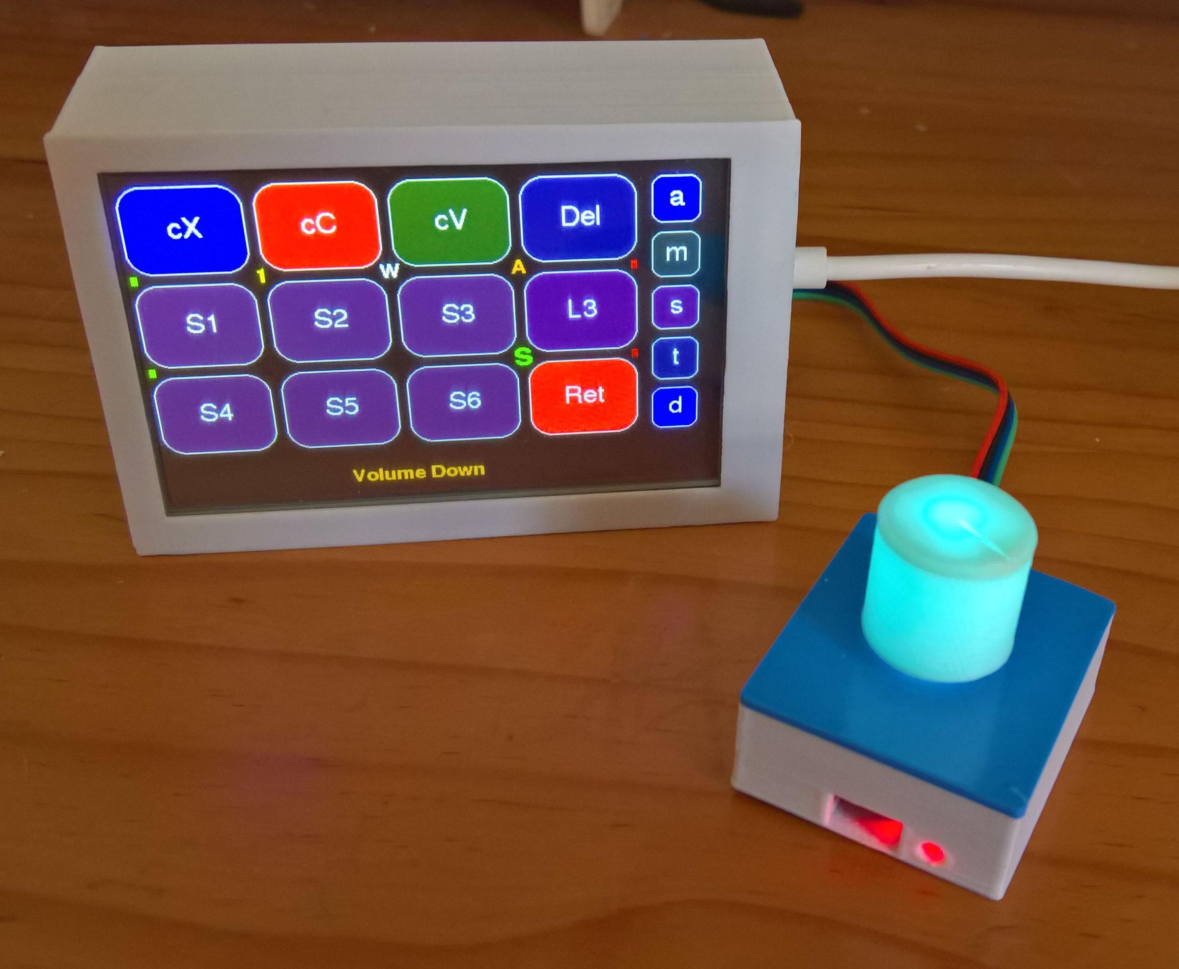
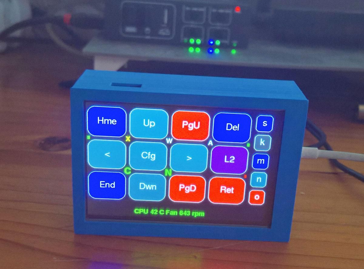
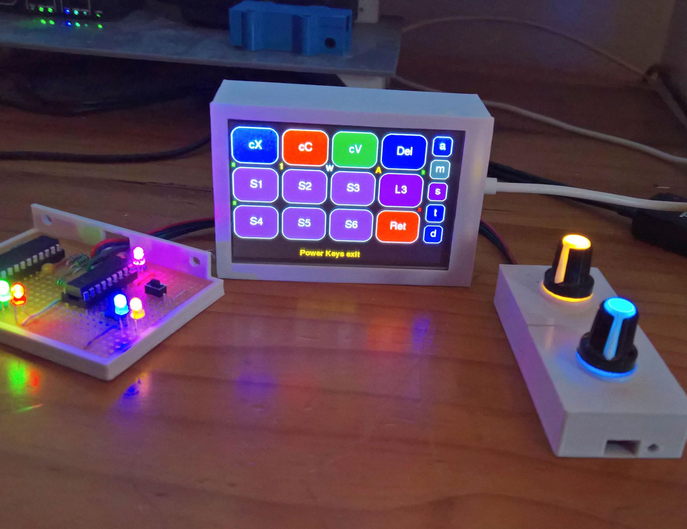
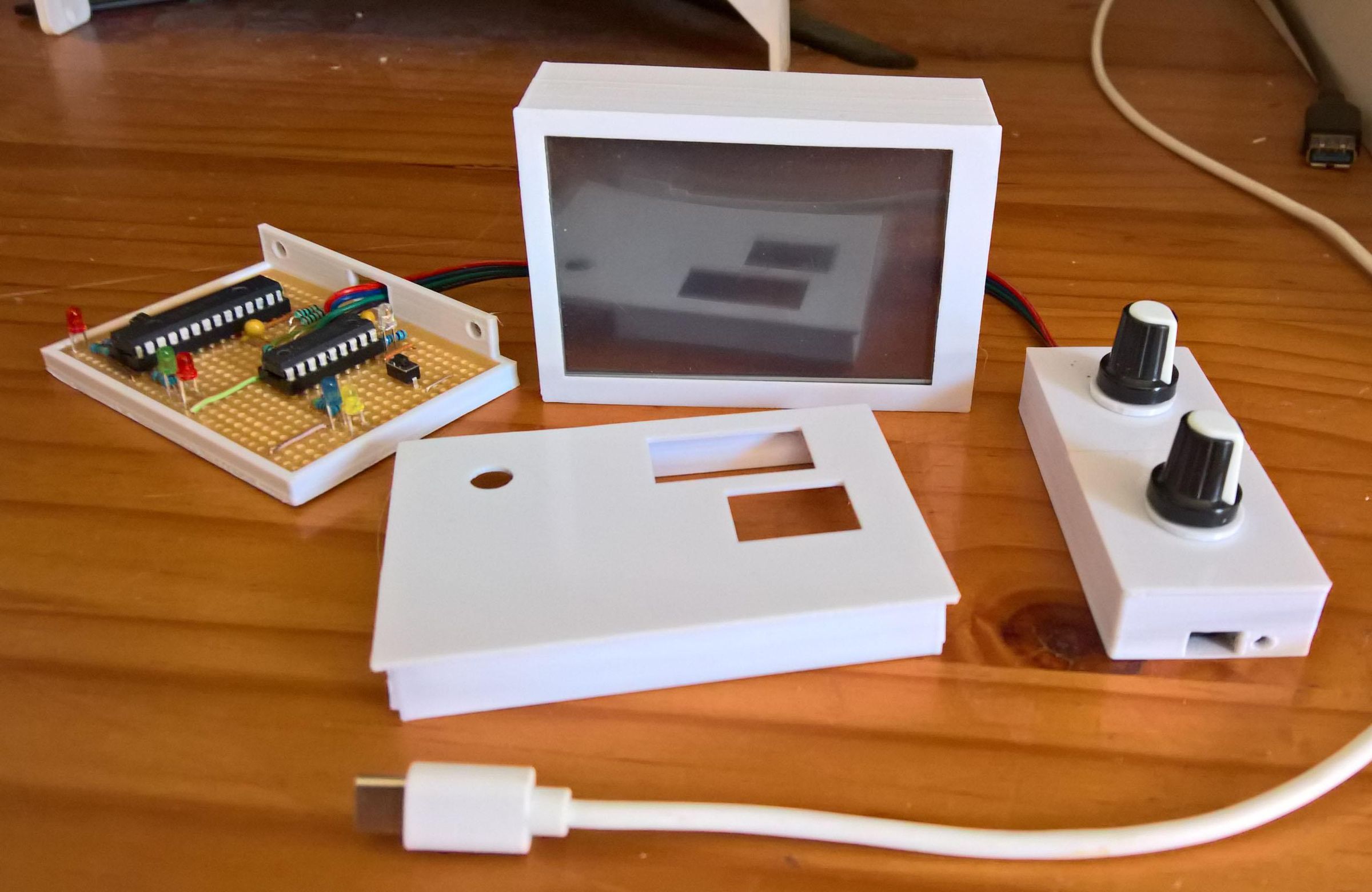
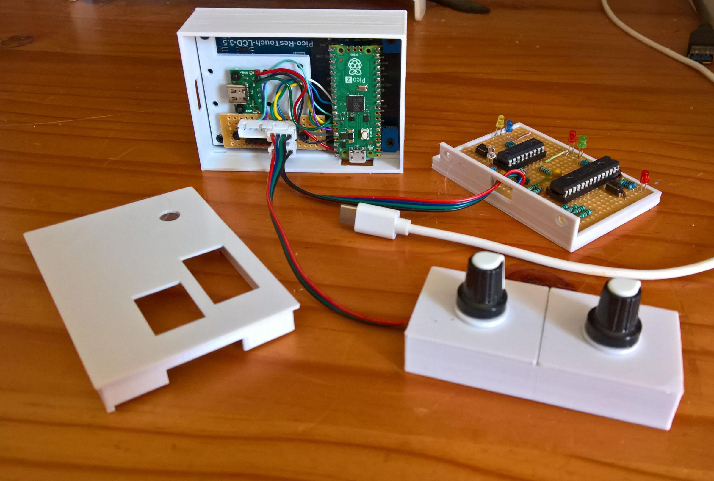
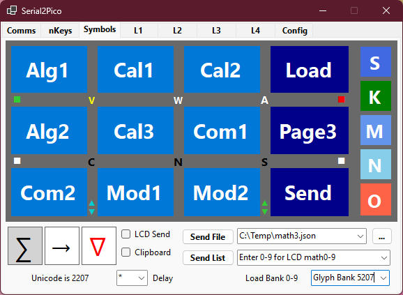
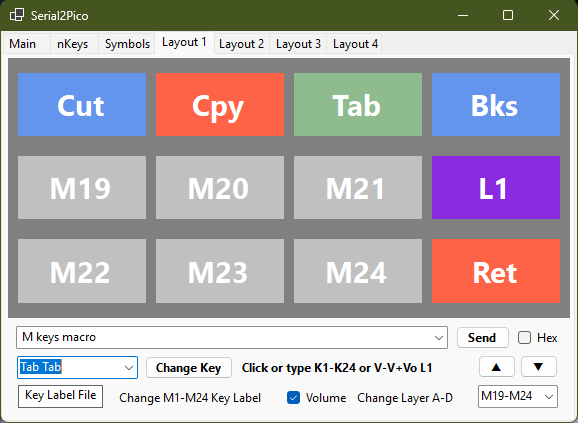
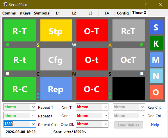
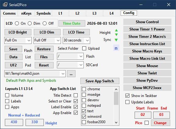
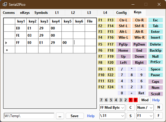
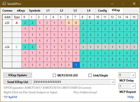
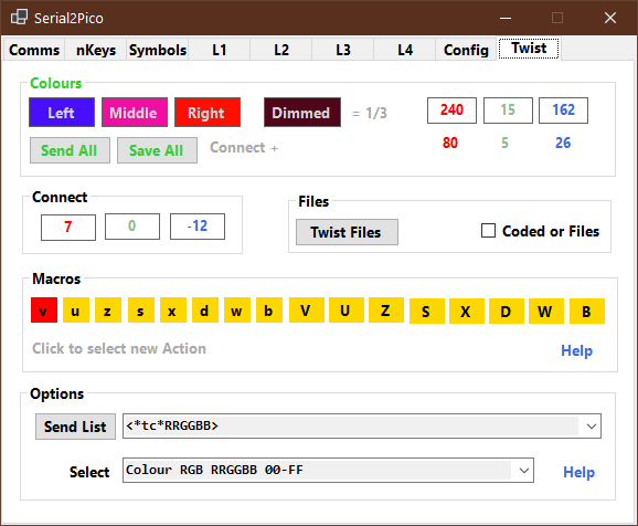
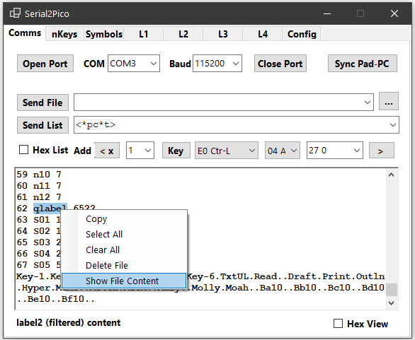
The aim of this instructable is: (1) to clearly show makers how to build a resistive touch LCD macropad, (2) add an i2c bus for external devices such as the Sparkfun Twist RGB rotary encoder used for Volume, Scrolling, Zooming etc., and the series of Microchip MCP23xxx GPIO expanders which are used to add physical buttons and relays, i.e. more input and output devices, (3) program and configure the macropad, and (4) install and use the macropad's PC control-and configuration application which run as a true actionable Windows mimic of the macropad. Should there be enough interest a follow-up Instructable will show how to construct the two types of i2c external devices mentioned, and also how to build and use the capacitive touch version of this macropad, which has more capabilities than the macropad described here.
The Raspberry Pi Pico 2 RP2350, is used as a file-and-folder-based Touch LCD macropad - where everything that the macropad is using are files and folders, which are located on an SD Card and Flash memory. Seven file-types are used: (a) file-path-pointers (similar to symbolic links), used for both labels and nKeys, (b) normal key-based macros, (c) text-strings up to 2GB in size, (d) link-files to expand macro to sequences of macros, (e) *codes to configure the appearance of the macropad and execute more complex sets of macros, (f) JSON files used for PC Application switch rules and names, and math and symbol descriptions, and (g) key-label-definitions. From Layout 2 (Configuration), at least 92,628 files or "nKeys", grouped as 36 sets of type (a) (aA01-xX996 and 0001-9996), and 14,940 files of types (b) to (e), are directly available from the right-side touch Pad [n] - with the Pad character showing the current selected nKeys character set.
From this it should be clear that almost any Windows PC-based task can be executed using the macropad, and it avoids the re-compilation requirement of conventional script-based macropads and keyboards. This is because it can be instantly re-programmed – either by sending and executing star-codes instructions, or manually using the macropad's own editor or its associated PC Application - by familiar (copy, rename, delete, and move), file and folder manipulation operations, on both the SD Card storage and Flash memory.
As the macropad has been constructed for six different resistive touch LCDs, and two different capacitive touch LCDs, all eight different macropad types will not be described here. The capacitive touch LCD macropad has additional features such as audio manipulation via an Audio codec, programmable power management (PMIC) for both the macropad and the i2c devices, and a real-time-clock (RTC).
An overview of all the different macropad options is available by scanning through the GitHub pages of the project which can be accessed in three sections: (1) The Macropad in general and the resistive macropad options. (2) The two capacitive macropads (2) The PC Application. The source code of the macropad is available from the first two sections, and if there is a need, instructions on how to compile and build the firmware are available.
Supplies
Tools: You will need a basic set of tools (long-nosed pliers, side-cutter, screwdriver, wire-stripper, (electric) drill etc,), low wattage soldering iron and resin-based thin (1mm or less diameter) 60cm long solder, sanding paper, and a 3D printer for the macropad case (or a friend with a 3D printer) and about 100g of PLA 3D printer filament (only one colour is needed such as blue, white, black, red etc.)
Materials: These are not difficult to obtain materials:
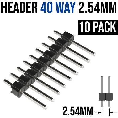
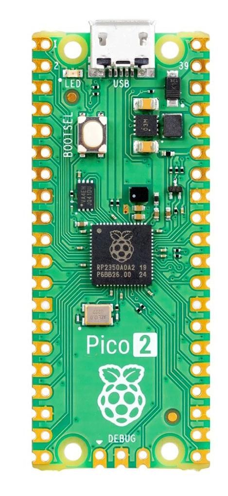
(1) Raspberry Pi Pico 2 RP2350 (stepping A2 A3 or A4). These are sometimes supplied with two 20 pin header strips. If you have the Pico 1 visit the GitHub repository and choose the Pico1 link, then from the Source1 link click on the UF2 file. download and use it instead of the Pico 2 UF2 file used here.
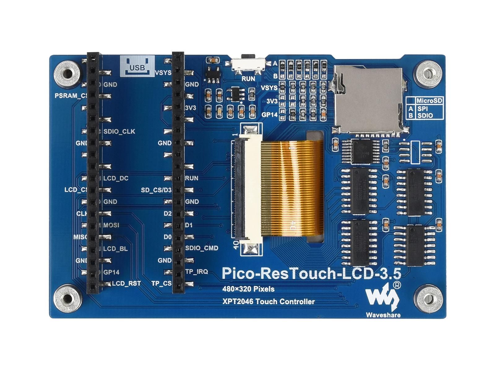
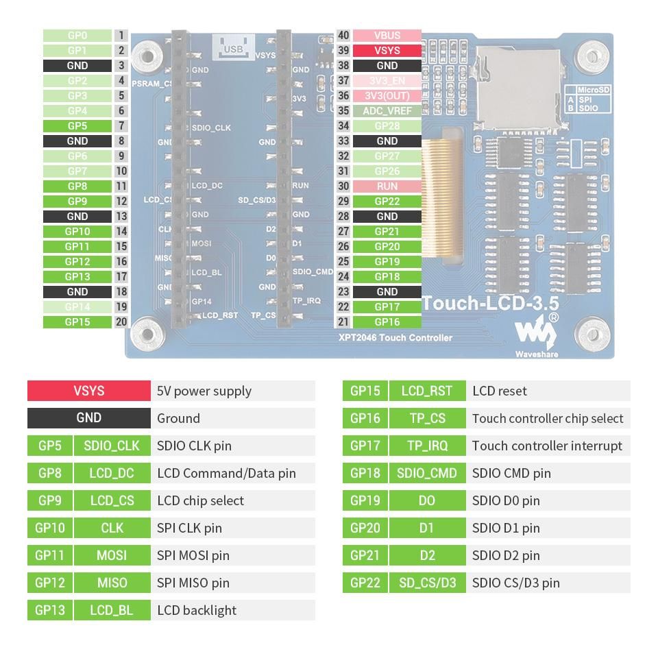
(2) Waveshare 3.5inch Touch Display Module for Raspberry Pi Pico
(3) Small section of 6 x 18 (6 connected rows) strip-board or proto-board.
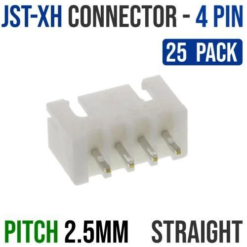
(4) JST-XH 4-pin 2.54mm through-hole male shrouded-header connector. This is used to connect your i2c devices. You can use any other 4-pin connector because you can fit the corresponding mated-part on the i2c device.
(5) 4 M3 x 6mm sunken-head and 4 M2.5 x 8mm cheese-head bolts and 8 M2.5 nuts.
(6) Six colours thin stranded connection wire 22 or 24 AWG total length 100 cm.
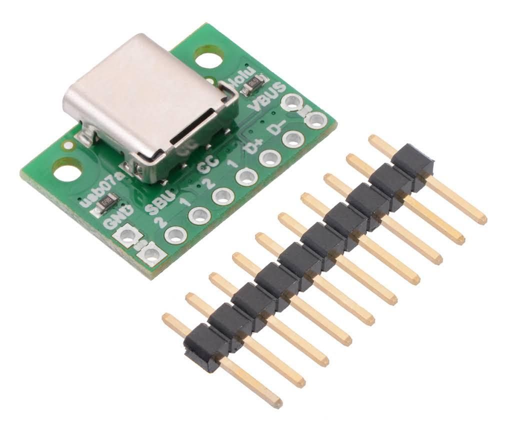
(7) USB-C breakout board. This should have at least four connectors for the two data lines D+ and D-, and the two power line 5v and Ground. Choose one without a voltage regulator but make sure it has two 5k1 resistors fitted. If you cannot get hold of it immediately use a micro USB cable connected to the Pico 2 directly until you can get the USB-C breakout board.
(8) Optionally you can protect the resistive touch surface of the LCD by placing a thin Laser Transparency Film or OHP film, between the LCD and the front of the case. It should slightly smaller than the inside of the case. The laser film has a rough and smooth side - place the rough side in contact with the LCD.
Construction
Assembly Steps
1. 3D Print and Enclosure Preparation
Download and then unzip and use the STL files. 3D-print the 5 enclosure parts: Front Case, Back Case, Two Small Clamps, and the USB-C Support Bracket.
- Smooth the 3D-printed edges using fine-grit sandpaper.
- Test-fit the LCD by sliding it into the front case at a angle.
- File down the two side retention clamps if they are too big for the rectangular side holds.
2. SD Card Setup
- Format a 16GB or 32GB MicroSD Card using FAT32 (do not use exFAT or NTFS).
- Copy the contents of the provided zip files (AppSwitchExample, SDCard-Labels, SDCard-MathSets, Exercise1-files, Exercise2-files, Files4Twist) to the SD Card. If there are folders copy the folders with the files inside the folders to the SD Card.
Wiring Options
Choose one of the three options based on your hardware configuration:
The options depends on which Pico 2 you have (headers or no headers), and whether you want (a) to use a USB-C connection on the side of the case, and (b) use the range of I2C add-ons such as the Sparkfun Twist rotary encoders and Microchip MCP23xx range of GPIO extenders.
If you have a Pico 2 with all header pins already soldered, use option 2. If you have a Pico 2 with no header pins soldered use option 1 (this is the recommended option). If you have a Pico 2 with no header pins soldered, or all header pins soldered and you only want to use the basic MacroPad with no i2c extensions such as the Twist rotary encoders or the GPIO extenders, and you also are going to use the MacroPad lying flat with the USB cable connected directly to the Pico 2's micro-USB socket which then comes out of the top of the case - then use option 3, which involves the least extra work, and little or no soldering.
Option 1: Recommended Setup (No pre-soldered Headers)
- Cut the male header strip into 10-pin, 10-pin, and 2-pin lengths.
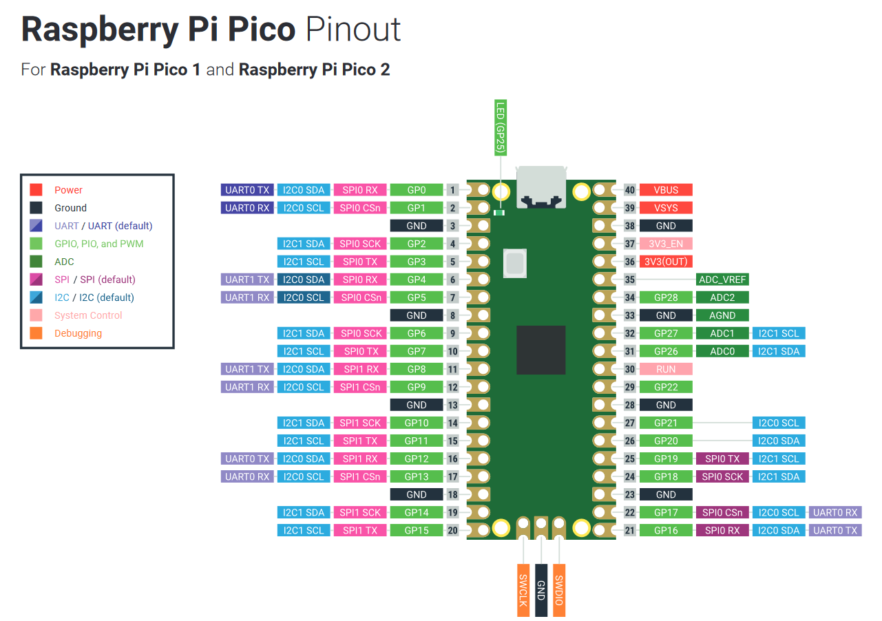
- Solder the headers to the Pico 2 as in 3, 4, and 5:
- 10-pin strip: Pins 11 to 20
- 10-pin strip: Pins 21 to 30
- 2-pin strip: Pins 38 and 39
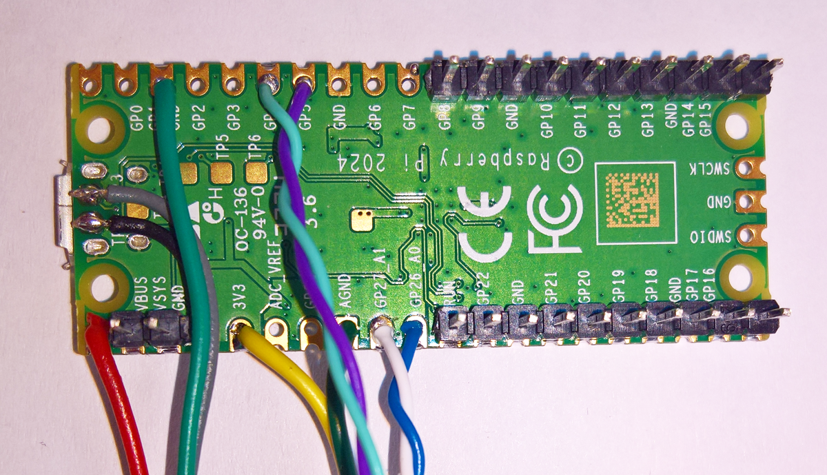
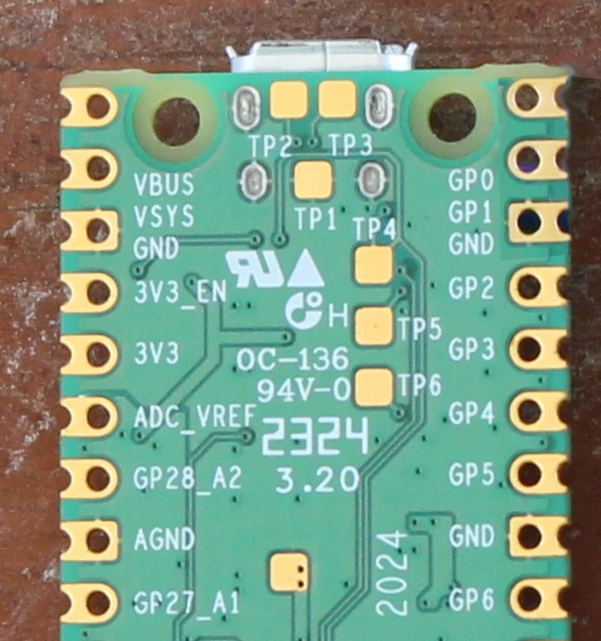
- Solder two thin wires to test points on the underside of the Pico 2 for USB D+ and D- as in 7, 8:
- TP2: USB D- (Data Minus) — Black wire
- TP3: USB D+ (Data Plus) — Grey wire
- Solder power connections to the USB breakout board using slightly thicker wire as in 10, 11:
- Pin 40 (VBUS): Power — Red wire
- Pin 38 or Pin 3 (GND): Ground — Green wire
- Solder the expansion bus lines as in 13, 14, 15, 16:
- GP26: I2C Data (SDA) — Blue wire
- GP27: I2C Clock (SCL) — White wire
- Pin 36 (3V3): Logic Power — Yellow wire
- Pin 3 or 38 (GND): Logic Ground — Green wire
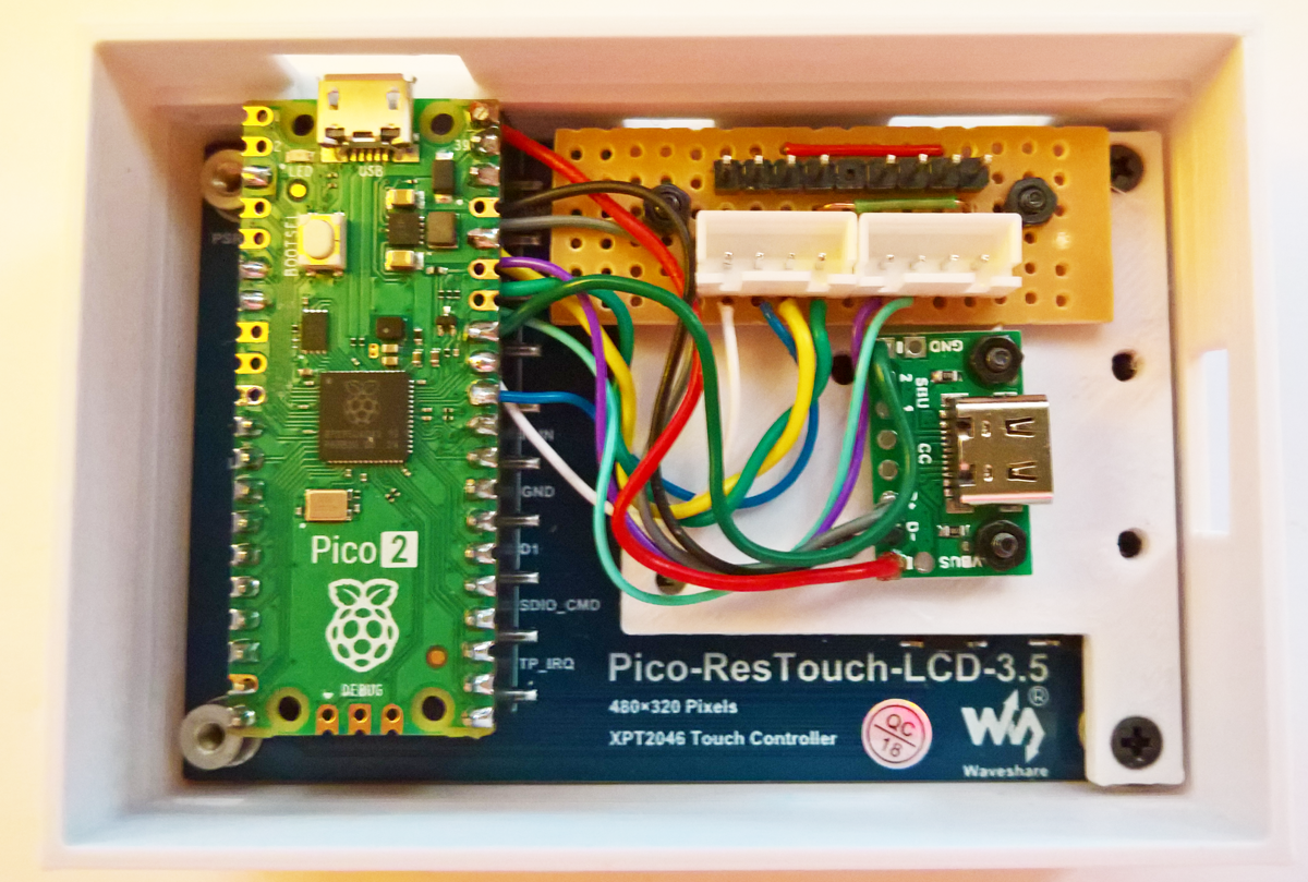
- Insert the Pico 2 into the two 16-pin rows on the rear of the LCD board, aligning the two 10-pin rows farthest from the USB socket.
Option 2: Pre-soldered Header Setup
- Solder two thin wires directly to test points TP2 (D-) and TP3 (D+) beneath the USB socket.
- Solder the USB power and I2C expansion wires directly to the exposed top tips of the header pins (VBUS Pin 40, GND Pin 38/3, GP26, GP27, and 3V3 Pin 36).
- Align and seat the Pico 2 onto the LCD header rows matching the PCB silkscreen orientation.
Option 3: Basic Setup (No Assembly/Soldering Required if the Pico 2 + Headers are used)
- If headers are missing, place two 20-pin header strips into a breadboard to hold alignment. Place the Pico 2 on top and solder all 40 pins.
- Skip adding the USB breakout wiring and expansion boards.
- Seat the Pico 2 into the LCD board. Power. program and use the macropad directly through the Pico 2’s native Micro-USB port at the top of the enclosure.
I2C Expansion Board Assembly (Required for Options 1 and 2)
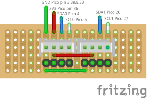
- Cut a piece of strip-board to 6 rows by 18 columns (copper tracks running horizontally across columns).
- Solder the male 4-pin JST-XH header into place. (If using two buses, install a second header adjacent to it and bridge 3V3 and GND).
- Connect the incoming wiring harness from the Pico 2 to the board traces in this order:
Pin 1 (Leftmost): GND
Pin 2: 3V3
Pin 3: GP26 (SDA)
Pin 4 (Rightmost): GP27 (SCL)
Loading Firmware + PC App Configuration
3.1 Flashing Firmware
- Connect the MacroPad to your PC using either USB connection.
- Hold down the BOOT button on the Pico 2, press and release the black RESET button on the LCD board, then release the BOOT button.
- A mass storage volume named RP2350 will appear on your PC.
- Unzip the macropadfirmware.zip file and then copy and paste, or drag and drop the provided macropad.uf2 file onto the RP2350 drive.
3.2 Touch Screen Calibration
- Upon restart, four calibration arrows will appear sequentially in the corners of the LCD.
- Tap the tip, or just inside the arrow tip, of each arrow once. If you make a mistake a pressed the tip of the same arrow twice, the macropad firmware will load but the buttons will not react to you pressing them. In that case do section 3.1 a, b, c again and then clear the Flash memory but using the nuke_universal.UF2 file. Then do the calibration again.
- Upon completion, the MacroPad boots into Layout 2, displaying the default yellow Volume control interface.
3.3 Setting Up the Windows PC Application (Serial2Pico)
- Install by unzipping to the Serial2Pico.zip file to any folder and launch the Serial2Pico.exe. It will prompt for the Microsoft .NET 8 runtime download if these are missing. Install then .NET files then open the Serial2Pico.exe file again.
- Go to the Comms Tab: Select the Pico COM port and set the baud rate to 115200.
- Go to the Config Tab: Point the folder directory to your extracted JSON symbol files (such as C:\MacroPad or C:\Temp).
- Ensure the start/end communication markers are set to < and >.
- Return to the Comms Tab and click Open Port. The application will display a real-time actionable visual mimic of the physical MacroPad screen. (You may have to open and close the PC App once at the very first start.)
Now read the section below which is called On First Start which is also in the text manual. If what is written there is already done, please ignore it. There is a description of what each tab of the PC App does on the GitHub pages for the PC App. There are also two exercises to show how to implement and use automatic PC App key switching - i.e. the keys on the Touch LCD change automatically depending on which PC Application such as Word or Notepad is open.
3.4. On First Start
There is a PC Windows-based app for an easy way of controlling and configuring the Touch Macropad - Serial2Pico. Serial2Pico is a configuration and control app for the Pico Touch LCD developed in Visual Studio 2022 C# .NET8, which is a mimic of the Pico macropad, with additional controls below the mimic, and navigation tabs above it.
If asked to do so, do a four-arrow corner calibration - press at the TIP of each arrow just ONCE. If you make a mistake and press the same corner twice it is likely that you will need a reset with the nuke.uf2 file (provided here in the GitHub Extras section), because the LCD will not read the correct corner keys being touched.
The default LCD settings are full brightness and when off full blank. Change these by pressing the second Pad on the right [k] or the grey Pad, and then press then press [*Cm] until *bb* shows in status line at the LCD bottom. Then press the [345] key twice (4 shows), press [ADD] and then press [EXE]. The normal use LCD Brightness is then set to 40 percent. Do the same for the LCD blank setting - press [*Cm] until *db* shows, then press the [012] key twice (1 shows), then press [ADD] and [EXE] - this sets the blank LCD to 10 percent brightness when in sleep mode. You can also add two numbers to set the brightness to 01 to 99 percent, i.e [*Cm] *bb*6[ADD]0[ADD][EXE] set to 60% and [*Cm] *db*0[ADD]3[ADD][EXE] set to 3%.
You can also increase the elapsed time period before the display dims - change it from the default 30 seconds to 3 minutes by selecting *tb* using the [*Cm] key, then press the [345] key once (3), and then press [ADD] and [EXE].
When the LCD has dimmed or blanked a first keypress is ignored - as it is used to restore the LCD to its selected brightness. Use [*Cm] *ks* [EXE] to enable or disable this key-skip behaviour.
The Volume Up and Down keys [V+] and [V-], are on by the default on a first start. To switch the Volume keys off press [Cfg] in Layout 2, then press [Vol]. Press the [Sav] key to save this Volume-off state - else it will be on again at the next switch-on.
The Volume-Mute long-press function is off by default (the navigation layout labels are L1 L2 L3 L4). To switch it to on when long-pressed on the navigation key press [Cfg][Opt]3x then Pad[o] - the labels will change to V1 V2 V3 V4.
As a replacement for the Volume [V+] key choose from a set of 54 options (Del Bks Tab aTb Ins Esc PrS aPr Ret Snp Osk UnD ReD Scr Cut Cpy Pst Tsk Run wX CPi Ts1 Ts6 K1-K24 Num Cap). With the Volume key off, press [Cfg] and then [Key] once for [Del] key options, and twice for [Ret] key options. Press the bottom Pad [o] to select from the other 54 options. Press the [Sav] key to save the option chosen.
When using the Symbols-Special-Character-Math-Greek-Algebra Keyboard - press Pad [s], watch out for MSWord insisting on capitalising the first letter of a sentence - which will change the math symbol to something else. Pressing [Load] will load a new symbol file from the SD Card - it will cycle through Math0 to Math9 and load that file if found. To load a specific Symbol Set use *ma*n with n = 0-9.
When pressing the [*Cm] key in the Macro Editor (green Pad [k]) it is not necessary to press [ADD] - it is added automatically. For example, to switch the serial port on/off press [*Cm] until *se* shows then press [EXE] - no need to press {ADD] before [EXE]. If you did press [ADD] by mistake just press the [*Cm] key again.
If the nKeys or the S1-S24 keys are used to print a large text file from the SD Card and there is extra line spaces use the *code *cr*0-3 to filter i.e. remove, CR 0D \n and LF 0A \r during sending nKeys text files. To add filter CR using the *Macro Editor: Press Pad[k], then press [*Cm] until *cr* shows then press [012]2x[ADD]EXE].
Serial Comms Start and End Markers can now be changed to a different ASCII character from the Pico and when changed from the PC App also to any byte value between 0 and 255 such as using 0x02 and 0x03 for Hex values, or enter < or > as text, in the textboxes in the new Change Start and End Marker section on the Config Tab. Use *1s*char for the Start marker and *1e*char for the End marker, or use *2s*char-char or *2e*char-char to change both start and end characters, or use *1s* or *1e* to reset both to the < > pair, or use *1s,e*000-255 to set to any value between 0 and 255, or use *1s,e*00-FF to set to any value between 0 and FF, or use *2s,e*000000-255255 to set start and end to any value between 0 and 255, or use *2s,e*0000-FFFF to set start and end to any value between 0 and FF, such as the 02/03 hexadecimal start/stop transmission pair. When it is changed on the Pico change it on the PC App before syncing, and when changed on the PC App via <*1s,e*char> instead of using the single <*2s*charchar> command, remember to keep on using < data >, as the translation to the new start char is done automatically when sending the *command to change the end character. Because the Pico Start and End marker settings are saved in the Config1 file, the values will be 0 after loading the new firmware - this condition where both are 0x00 are handled by setting them to the default < and >. Otherwise, use the Macro editor on the Pico and enter *1s* and save with the [Cfg]->[Sav] config button, before opening the PC App, or enter as *1s*< and *1e*> and save.
3.5 Further Use and Configuration
There are three sets of exercises available for using the PC App: (1) There is now an exercise that demonstrates how to use the Keys and Links tabs in the PC App. (2) An example of how to use five types of macros with the PC App Switching function. (3) An exercise on how to combine macros into longer sequences of macros, with delays and repeats added in between the execution of the macros.
The text manual has many other examples - but as it has its origin at the start of the macropad's development four years ago, not all sections of the manual are updated with changes in the latest versions of both the macropad and the PC App.
There are also two animated screen sequences which illustrate some of the macropads capabilities: Sequence 1 and Sequence 2.


Conclusion
6. Conclusion
This macropad has been in development since August 2022, and a consequence of this is that the functions originally envisaged is but a small fraction of its current abilities, which had an influence in its code planning. The code developed is not complete, nor is the current state of code fully tested. Both of these challenges will be addressed in the future.