Framing Water: a Tangible Game to Learn About Water Scarcity
by i3design in Living > Education
89 Views, 0 Favorites, 0 Comments
Framing Water: a Tangible Game to Learn About Water Scarcity
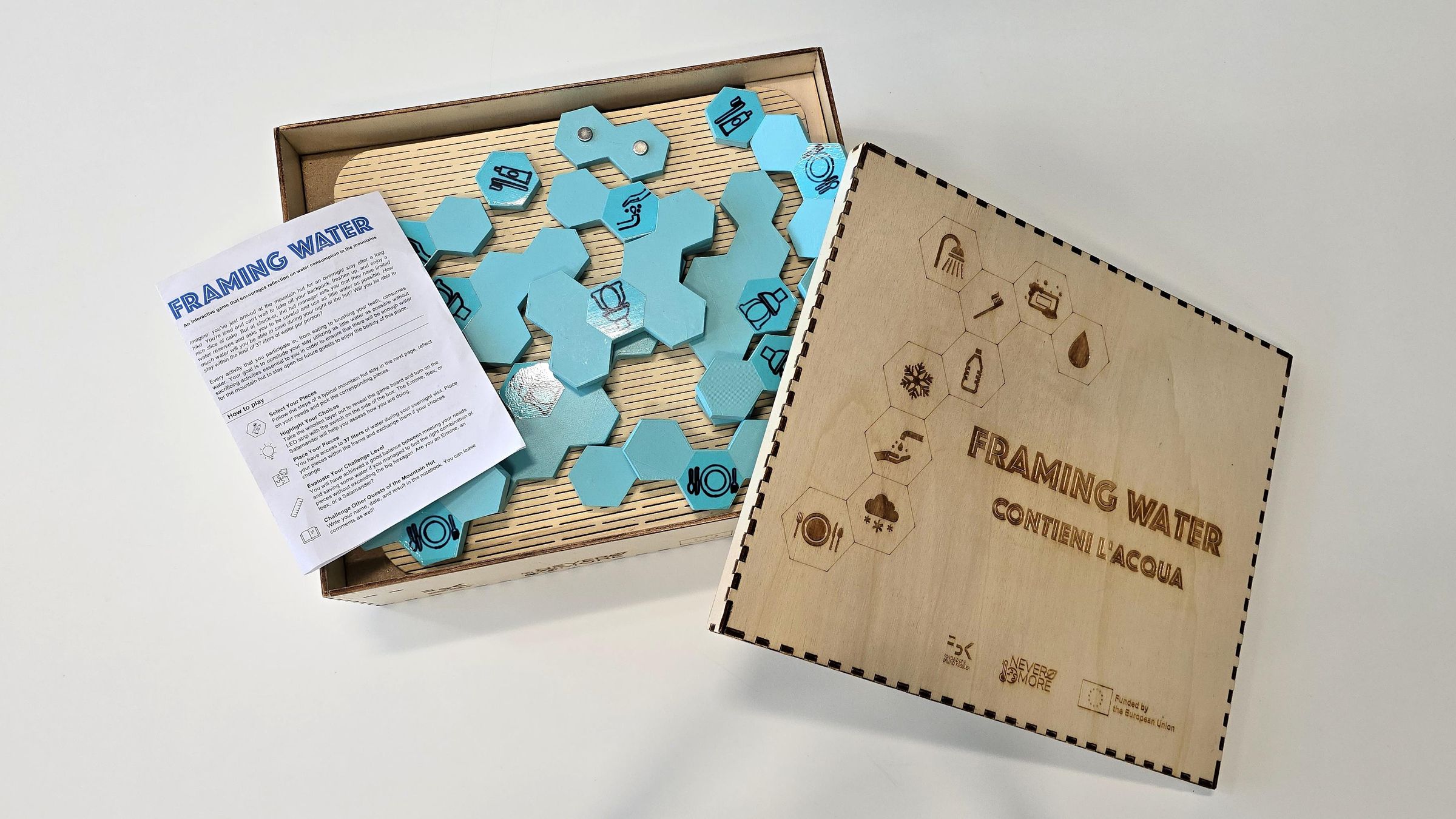
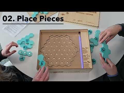
Framing Water is a reflective, data physicalization game designed for tourists staying in remote mountain huts in the Italian Alps, where water scarcity has become an increasing threat in tandem with overtourism. These huts, often disconnected from public utilities, must carefully balance visitor needs with limited natural resources to remain open. The game encourages players to reflect on their personal water consumption needs by making the invisible cost of water tangible. It was envisioned to be placed on the shelves of a common room in a mountain hut and played during social hours. While designed for a single player, it works well with two or more people, prompting discussion about social norms and sustainable water use.
At its core, the game invites players to make choices about everyday activities within a fixed water budget. The game unfolds over three phases: selecting pieces, placing pieces, and receiving feedback. Game pieces are composed of one or more hexagons, where each hexagon represents one liter of water. These hexagonal pieces represent typical water-consuming mountain hut activities, such as brushing teeth (1 liter), eating a snack made by the hut (2 liters), consuming a hot meal made by the hut (3 liters), a quick moment for personal hygiene (3 liters), and use of the toilet/WC (6 liters). The data is based on information retrieved from the Internet (e.g., the United Nations estimates that people need between 50 and 100 liters of water every day) and interviews with mountain hut managers.
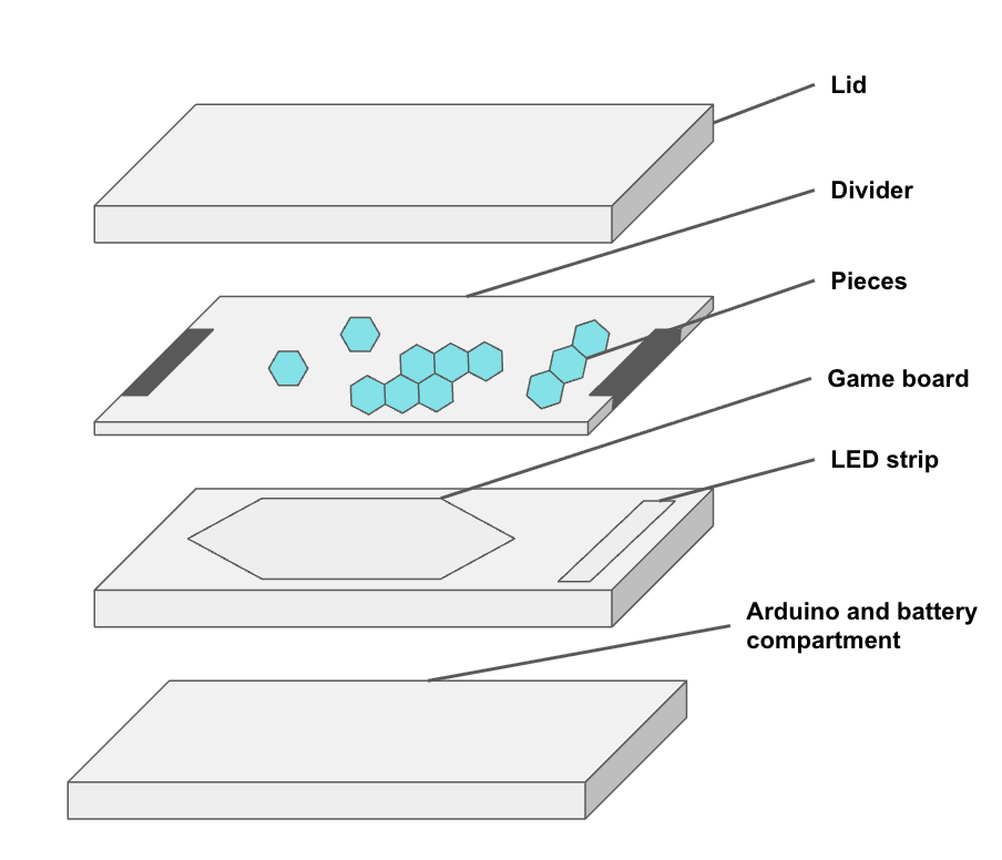
The game consists of a box with a lid, game pieces, a divider, a game board with 37 hexagons etched into the surface and framed by a raised hexagonal edge, an LED strip, animal descriptions, and an Arduino. The divider is placed on top of the game board to hold the pieces, creating a moment for the player to read instructions and reflect on their choices before selecting pieces and placing them on the game board. Once pieces are selected, the player turns on the LEDs by switching on the button on the back of the box, removes the divider, and attempts to place the chosen pieces within the board's bounds. As pieces are placed, a corresponding number of LEDs turn off, indicating remaining water. When the player finishes, they receive feedback as an animal description displayed next to the LED strip. Depending on total water use, the LEDs fall within one of three animal-based ranges, representing different relationships to water in a playful way. These animals are local to the region and reflect varying interactions with water.
This game was created as part of NEVERMORE, a Horizon Europe-funded project, and was prototyped with the tools, machines, and advice of the University of Trento Fablab. For a more in-depth look at the conceptual aspects of this game, see the scientific paper presenting it.
Note: Gameplay is supported in both English and Italian, but could be expanded to support other languages with some additional edits to the animal descriptions and instructions.
Supplies
General Materials
- General-purpose vinyl adhesive for box assembly
- Strong, transparent, multipurpose adhesive for mounting magnets and attaching the wood frame (e.g., Bostik Max Repair)
- Clear hot glue for insulating electronic components
- An assortment of sandpaper, starting from 240 grit and up to 1000 grit
- Strips of hook and loop Velcro with adhesive backing
- Pencil
- Fine tip permanent marker
- Electrical tape
- Double-sided tape
Tools
- Utility knife
- Deburring tool
- Wire strippers
- Angled needle tweezers
- Needle nose or jewelry pliers
- Cutting mat
- Rubber mallet
- A couple of F-clamps
- All-purpose paint brushes (one small brush for applying glue to the box joints and a larger one to apply the sealant to the box)
- Digital Multimeter
Software
- 3D slicing software (e.g., Bambu Studio)
- Vector graphics editor (e.g., Inkscape)
- Open-source parametric box generator (e.g., Boxes.py)
- Arduino IDE
Machines
- Soldering station
- 3D printer with multi-color printing option (e.g., Bambu Lab H2D)
- Laser Cutter (e.g., xTool P2S or Trotec Rayjet R500)
- Printer
Game Box and Board
- 5mm thick sheet of plywood that is at least 1066mm x 699mm
- 4mm thick sheet of Medium Density Fiberboard (MDF) 360mm x 280mm
- Clear sealant to protect against water and UV for internal and external use (ex. OBI brand Impregnante alta protezione all'acqua)
Note: The original prototype was made from 4mm-thick plywood. For best results, the wood should be as flat as possible, with no twists or bends, so the laser moves evenly across the surface. Four millimeters of thickness is suitably sturdy for the game board and box. Be advised that the box files available here were created for 5 mm-thick wood; if using a different thickness, a new file will be required.
3D Printed Game Pieces
- 2 - 1kg spools of PLA 1.75mm filament (one base color like Bambu Labs Translucent Ice Blue and one contrasting color for the icons)
Electronic Components
- 1m - 26 AWG flat ribbon cable with 37 conductors
- 50cm - Copper adhesive conductive tape 6.35mm wide
- 1 - Arduino Mega 2560
- 37 LED pixels - Adafruit 2847 RGBW addressable LEDs 144/meter
- 4 - AA batteries
- 1 - 4-cell AA battery holder with snap-on terminals
- 1 - PP3 connector to 1.2mm barrel connector
- 1 - Rocker switch off-on, on-off
- 1 - Solderable breadboard
- 1 - 1000 µF 10 V Aluminum Electrolytic Capacitor, Radial
- 1 - 560 ohms resistor
- Solder-free connector assortment box
- 90 - 10mm x 2mm Neodymium Magnets
- 37 - tattoo ink pots with 12mm openings
Print Game Pieces
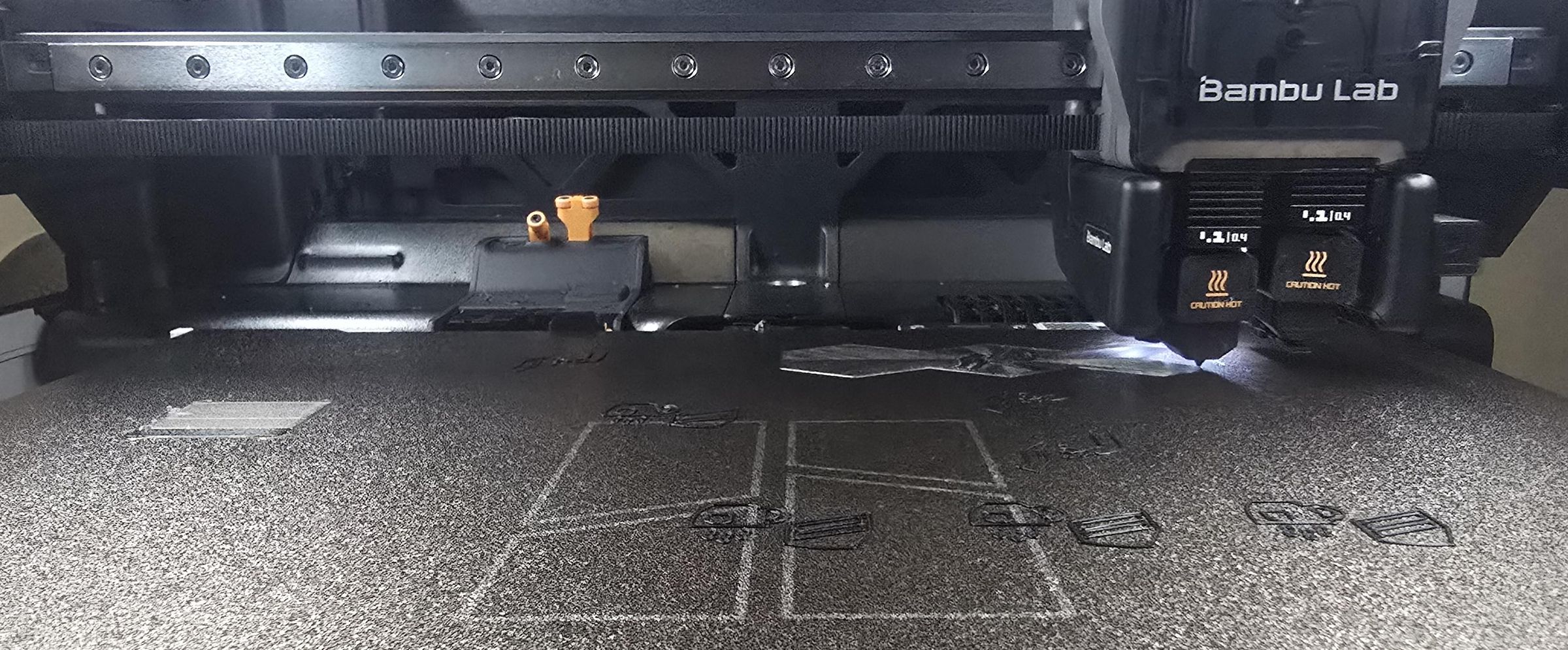
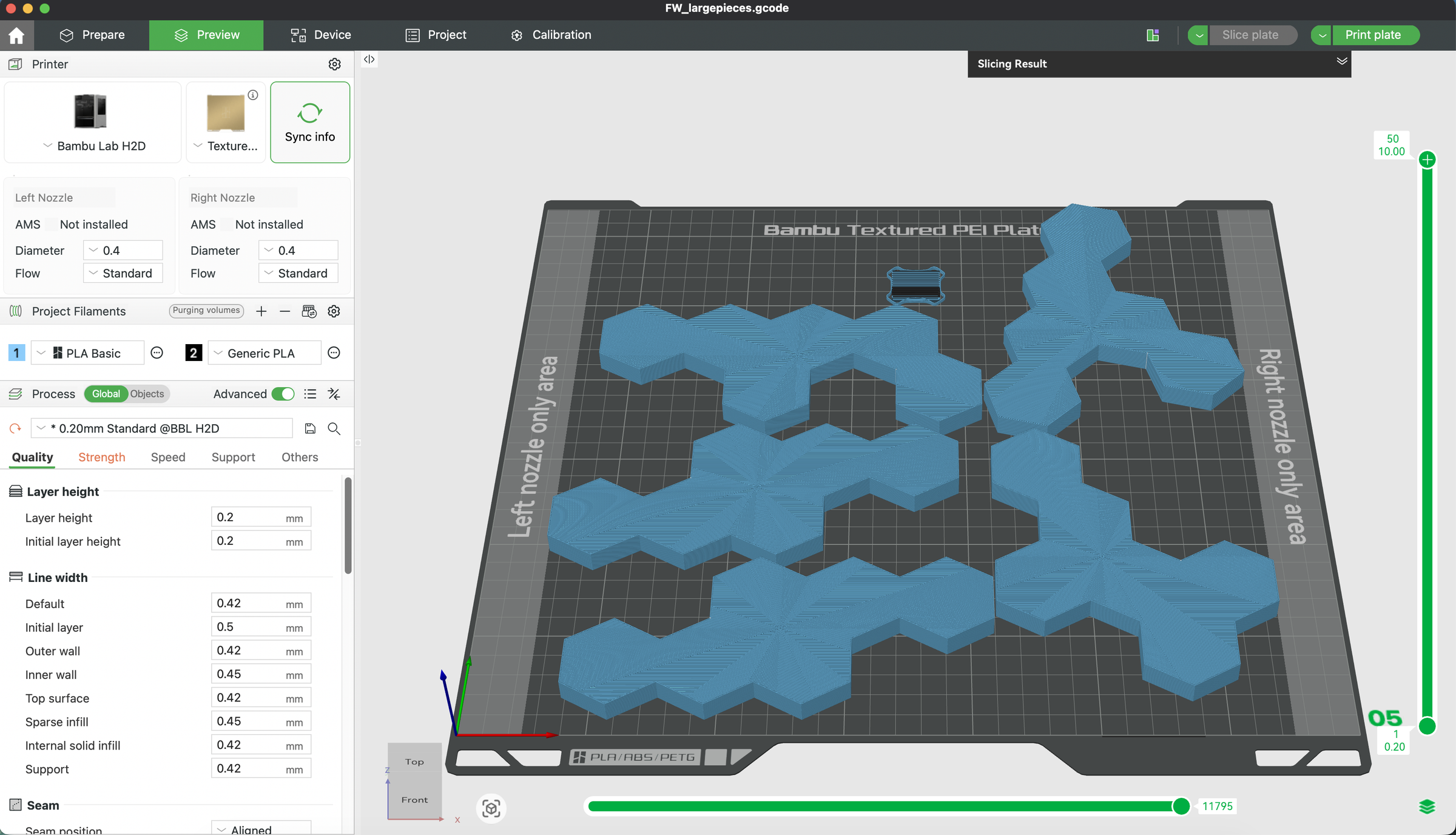
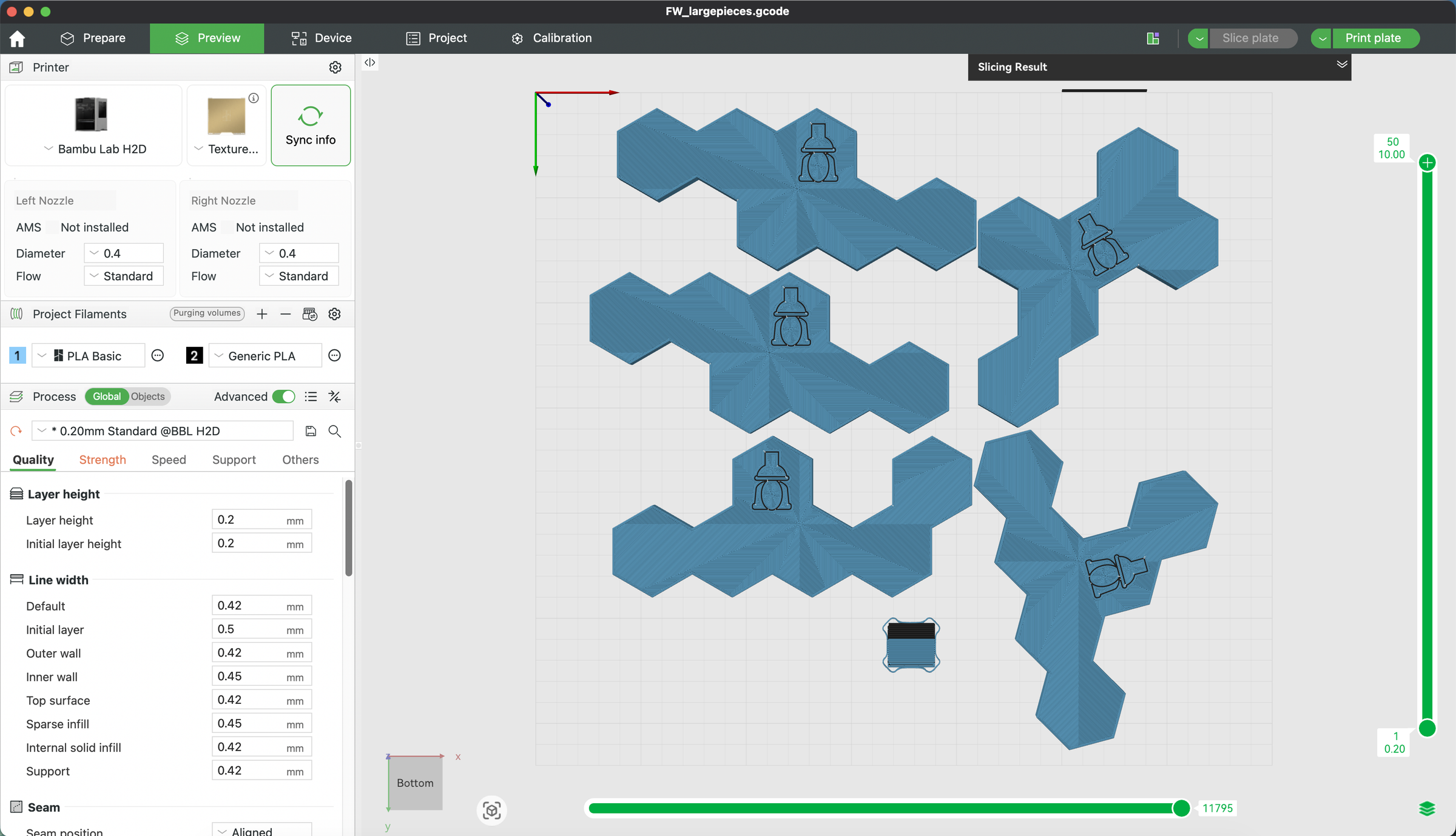
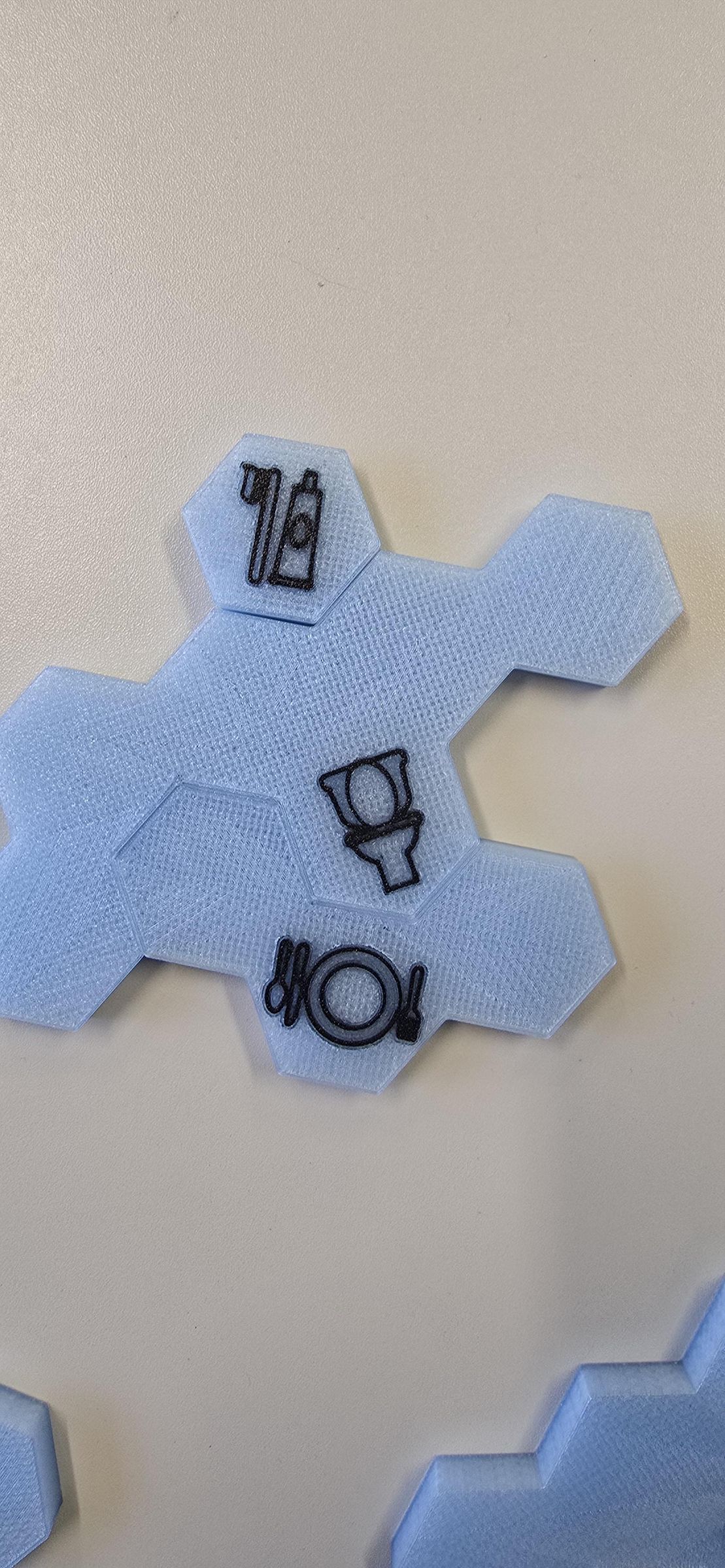
Game building can start with printing the pieces. Below are the instructions to follow, whether you have the same printer we used (Bambu Lab H2D) or a different one that requires file adjustments.
Please note that the print files include an extra game piece for each activity type, providing flexibility in choosing which pieces to play with. All the pieces (including the extras) can be stored in the game box.
Printing with a Bambu Lab H2D 3D printer
A Bambu Lab H2D 3D printer was used because it offers multicolor printing and an enclosure that helps protect against thermal shock. The g-code is attached below, with all the necessary pieces split across two files, and an estimated total print time of just under 15 hours. The g-code includes all the settings from Bambu Studio for the Bambu H2D printer. The files for immediate print are called FW_smallpieces.gcode.3mf and FW_largepieces.gcode.3mf.
Editing Prints to Accommodate other 3D printers
To use another 3D printer or change the settings, the .stl files and .svg icon files are available for modification.
The following number of pieces for each activity will need to be printed:
- 3 - Toothbrushing pieces
- 2 - Snack pieces
- 3 - Meal pieces
- 2 - Personal hygiene pieces
- 5 - WC pieces
Each .stl piece has an associated activity icon. Here, add the associated activity icon from the list below to the corresponding .stl.
The icon sizes should be scaled as follows for each piece to print correctly:
Icons X, Y, Z
Teeth brushing - X 24.79, Y 30.32, Z 2.00
Snack - X 29.00, Y 21.94, Z 2.00
Meal - X 33.32, Y 20.74, Z 2.00
Personal Hygiene - X 26.50, Y 22.69, Z 2.00
WC - X 18.97, Y 28.20, Z 2.00
Additionally, the icons print best when they are printed on the plate. The icon's height in relation to the print bed should be set to 0.88 on the Z-axis.
The strength settings are:
- Walls loops - 2
- Top/bottom/internal shells surface pattern - Octagram Spiral
- Sparse infill - 35%
- Sparse infill pattern - Gyroid
Note: When translucent PLA is used, the strength settings work together to create pieces that resemble ice.


Clean Up Pieces
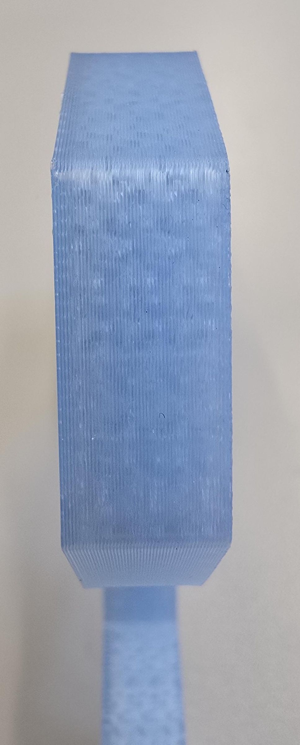
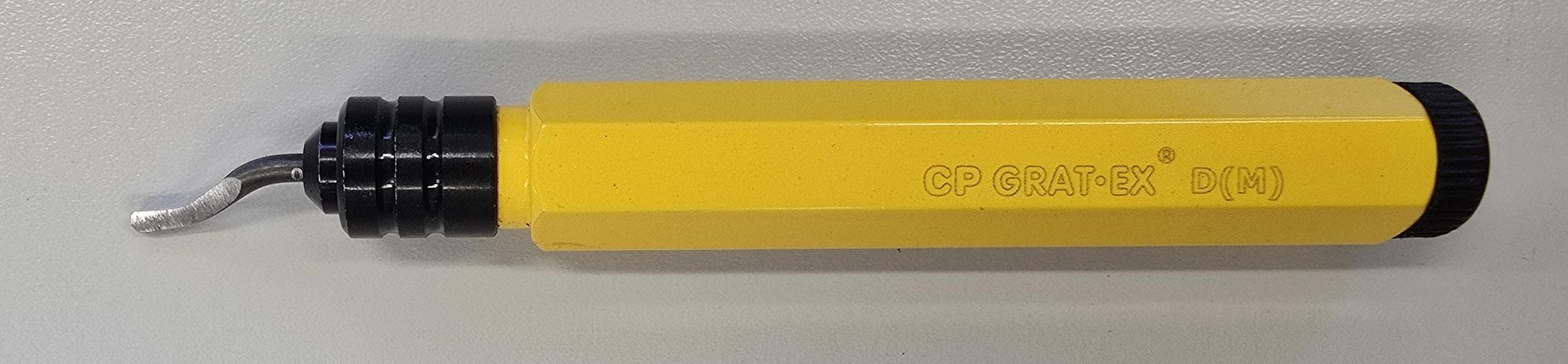
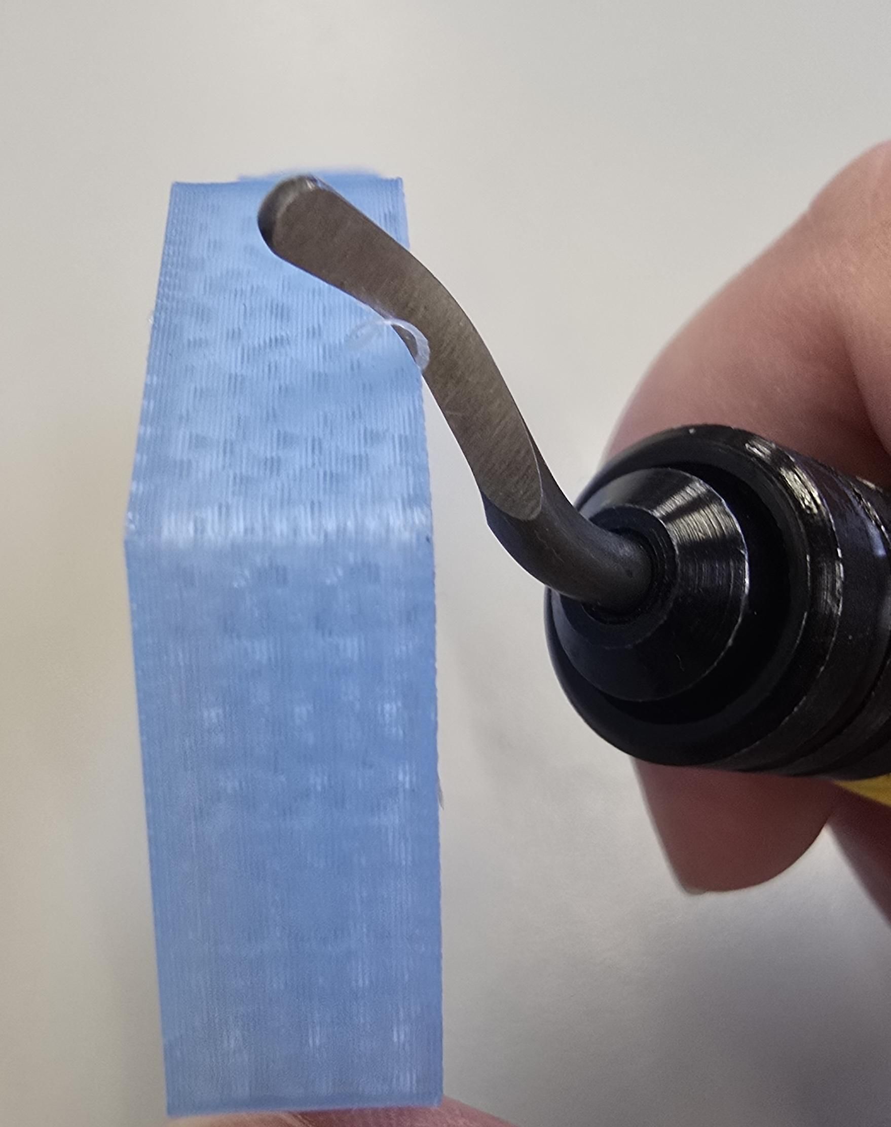
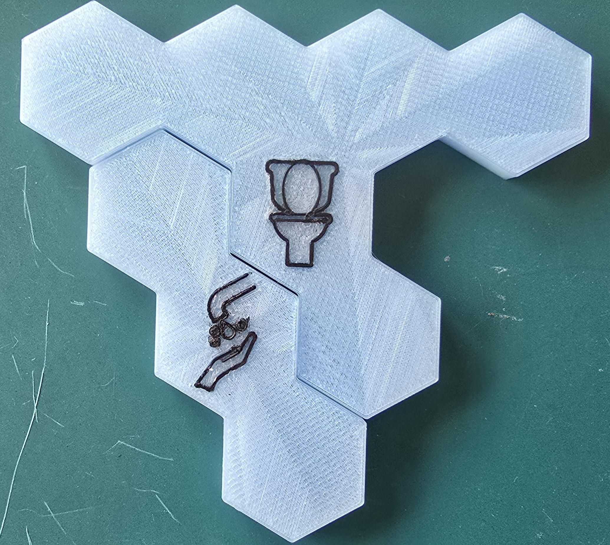
After printing, use a deburring tool along the perimeter of each piece to remove sharp edges and improve fit when pieces are interlocked. A high-grit sandpaper can be used on any burrs of PLA that remain.
Note: Be careful not to cut too deeply or sand too heavily, as this can create holes in the puzzle pieces or change their surface color or texture.
Laser-Cut Game Board and Divider
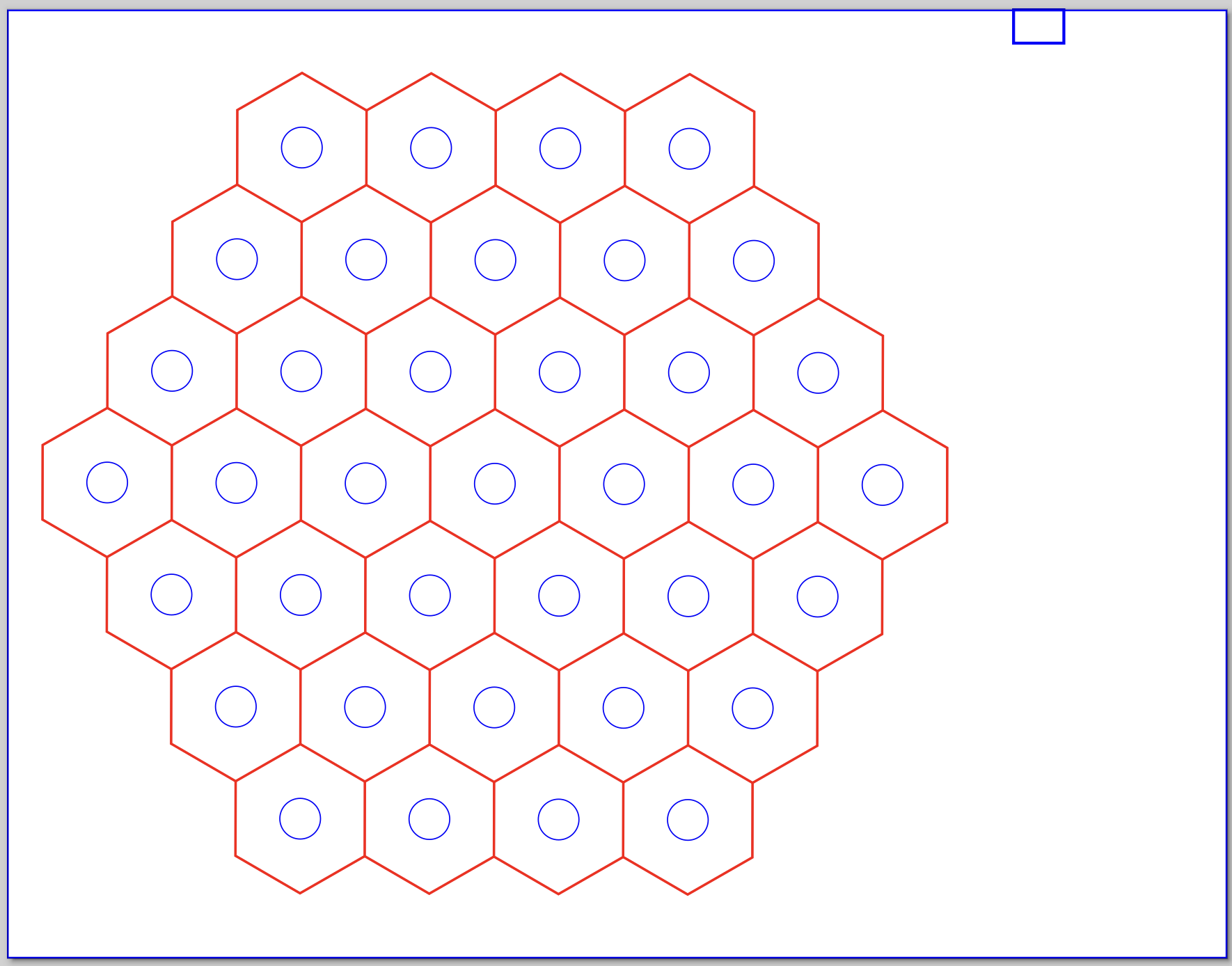
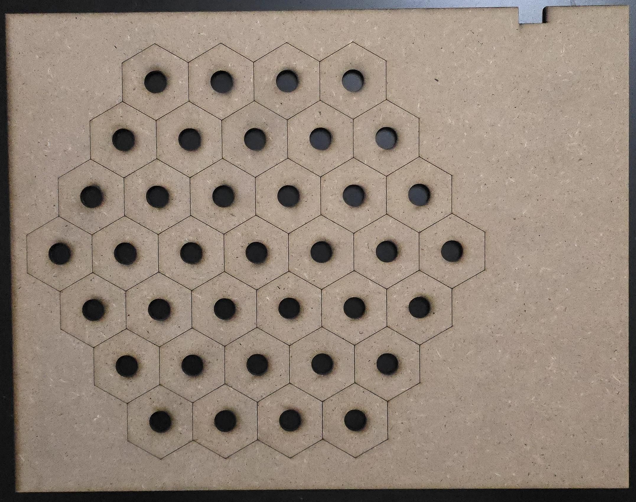
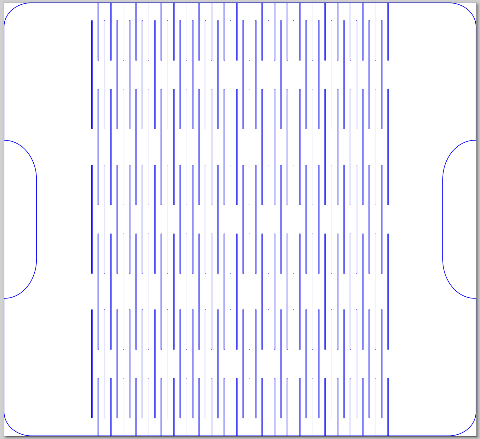
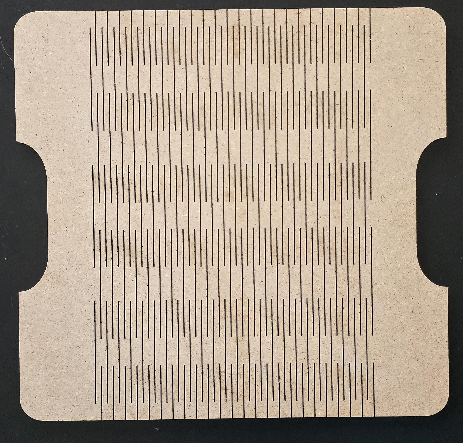
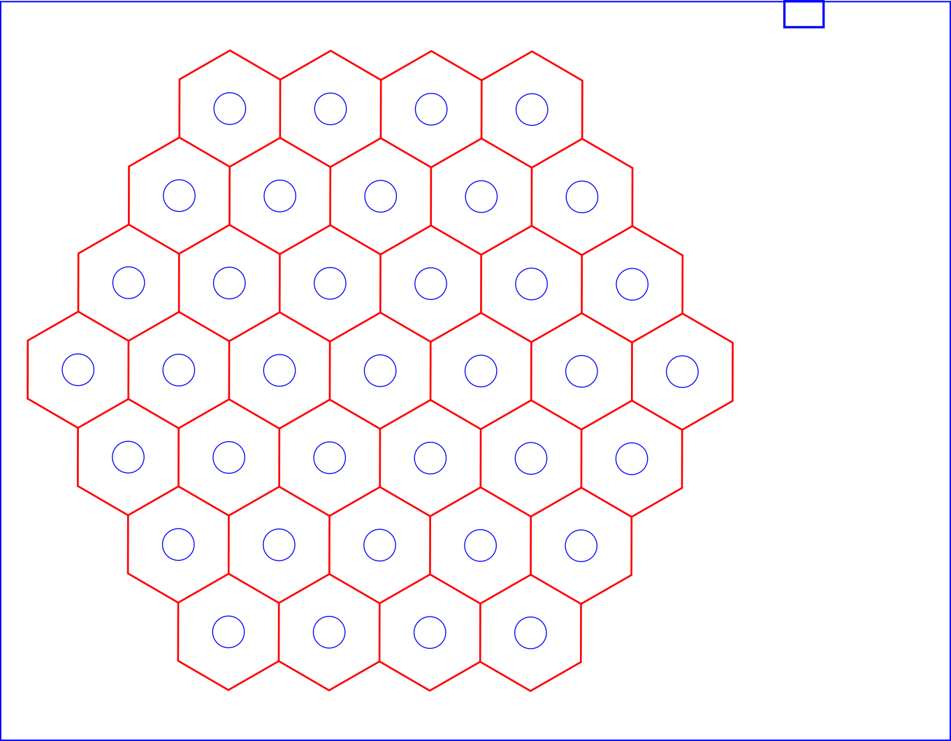
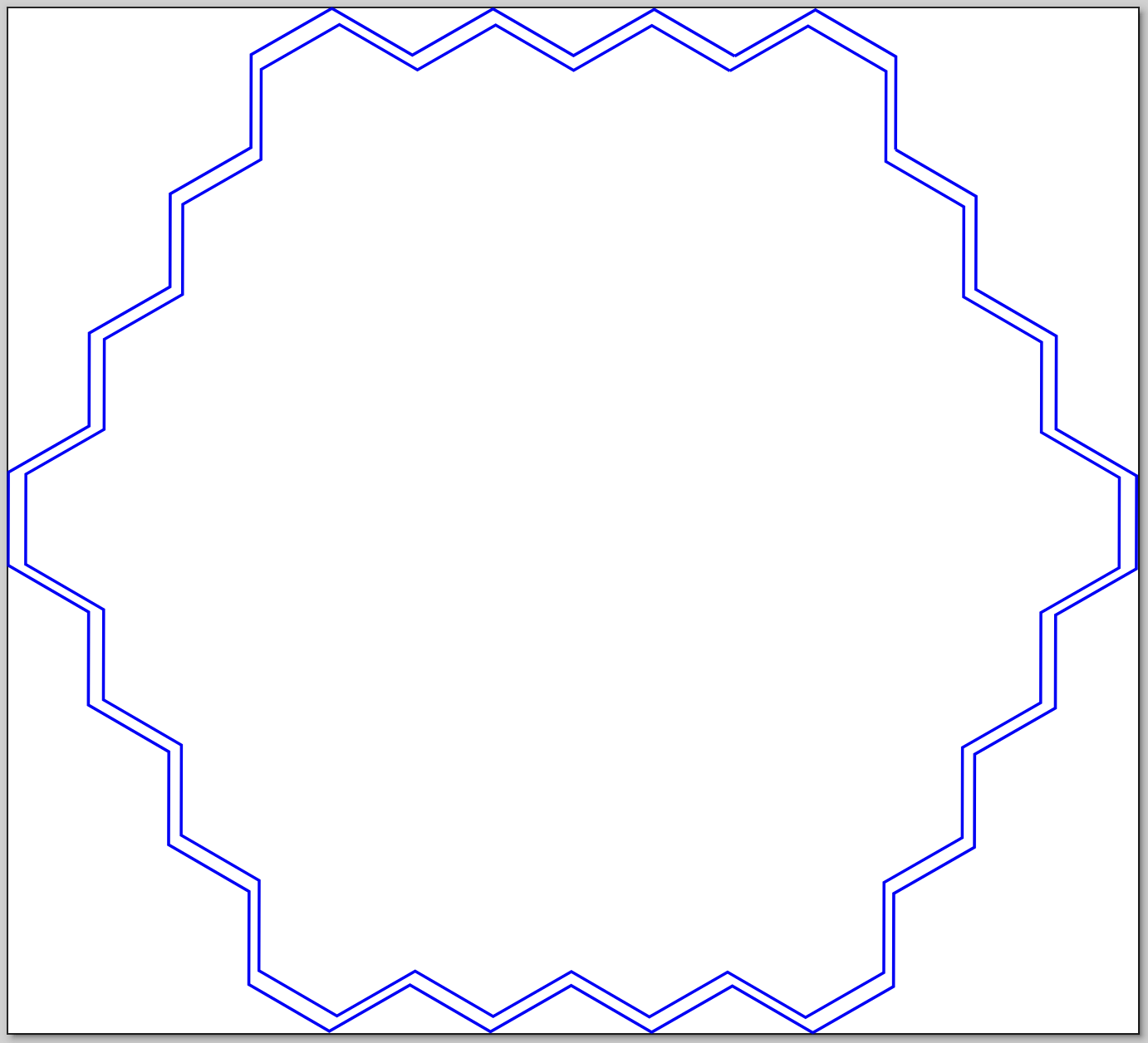
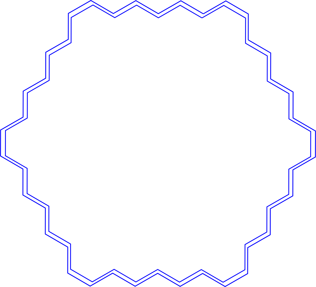
The game board is made of 4 mm-thick MDF and was created using the scoring and cutting methods of the xTool P2S laser cutter. The blue lines indicate the cutting method, and the red lines indicate the scoring technique used to create the foundation of the game board in a large hexagonal shape. The small opening cut into the board in the upper-right corner is for the LED strip wires to be threaded into the game box.
The divider is also made of 4 mm-thick MDF, only utilizing the cutting method.
Once these pieces have been cut, clean the cut lines, sand as needed, and set them aside for future steps.
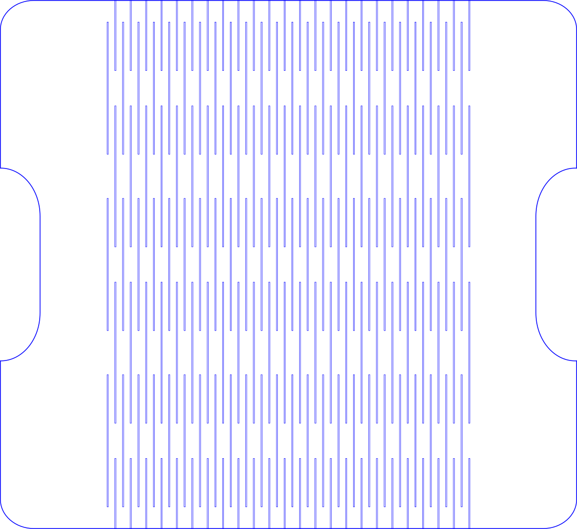
Laser Cut Game Box, Frame, Actuation Board, and Animal Descriptions
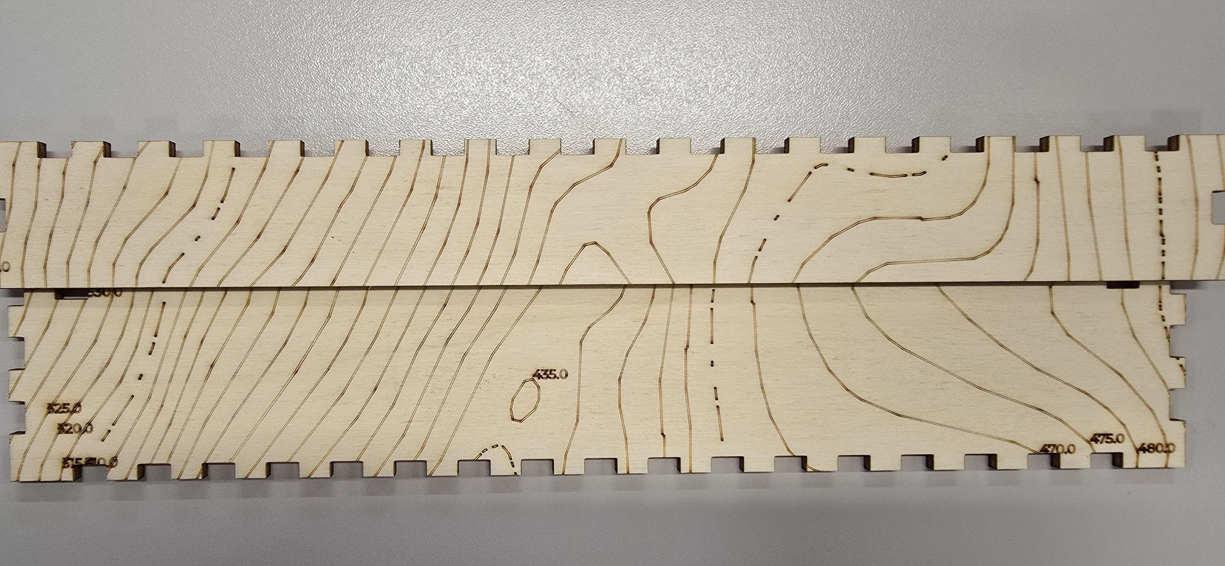
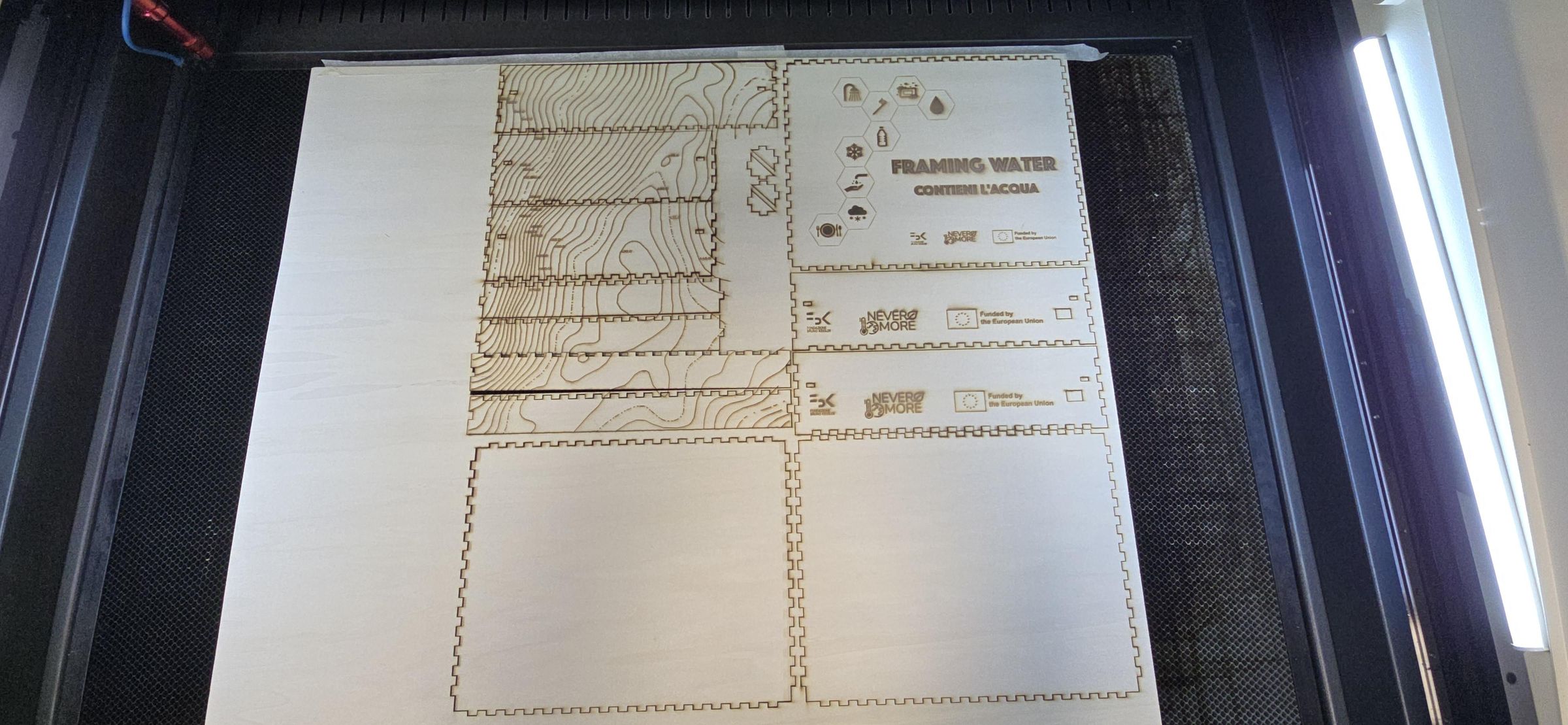
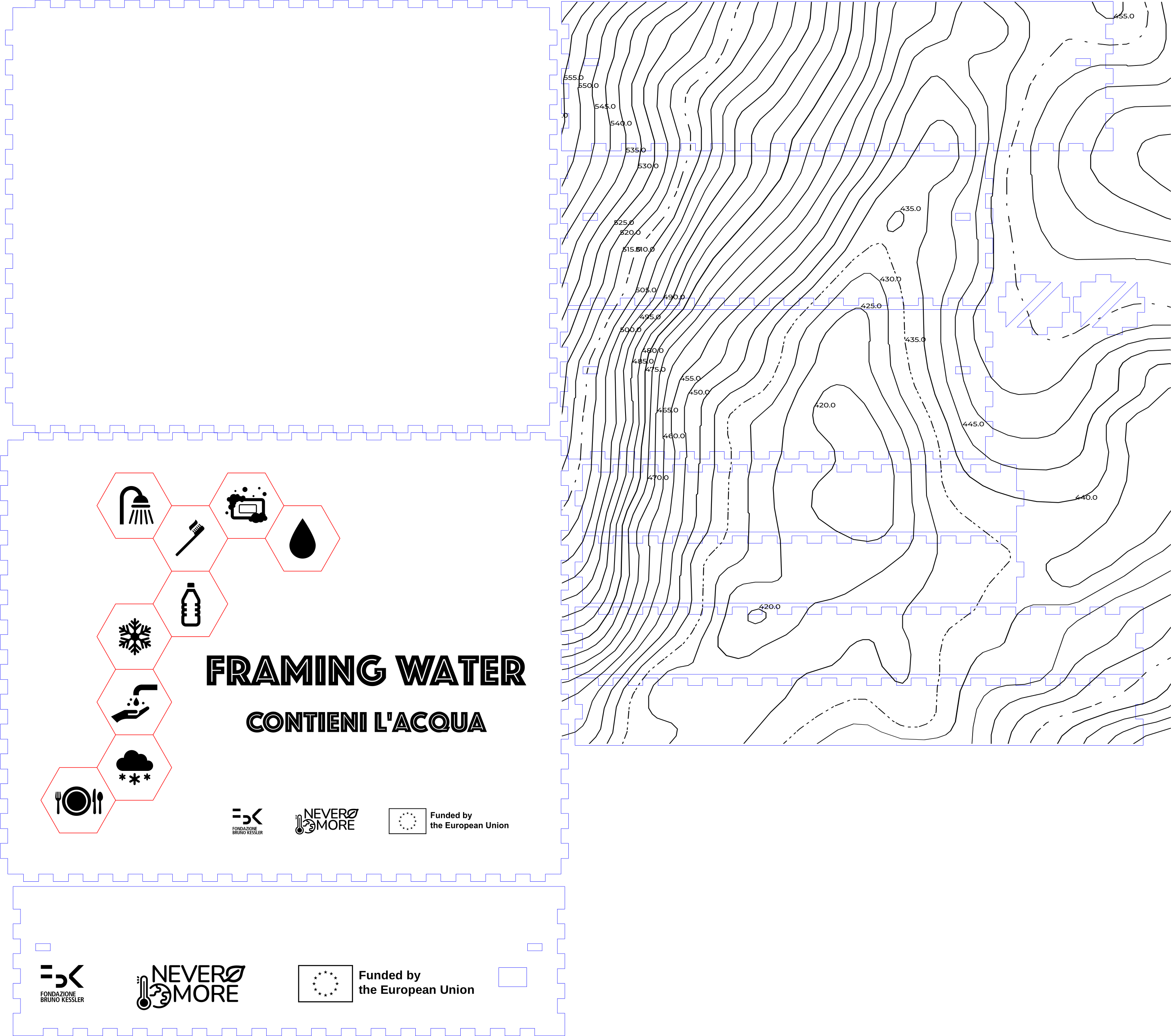
The game box is a blend of a universal box with a lid and an electronics box, so that the interior triangle supports hold the game board. Two files were generated and merged to create the game box file.
These pieces are all made of 5mm thick plywood. A large laser cutter, Trotec Rayjet R500, was used to cut multiple boxes at once. Smaller laser cutters can be used if the raw materials fit easily on the laser bed.
Engraved parts:
- Icons and text on the game lid
- Partnership icons on the side of the box
- A topographic map-style
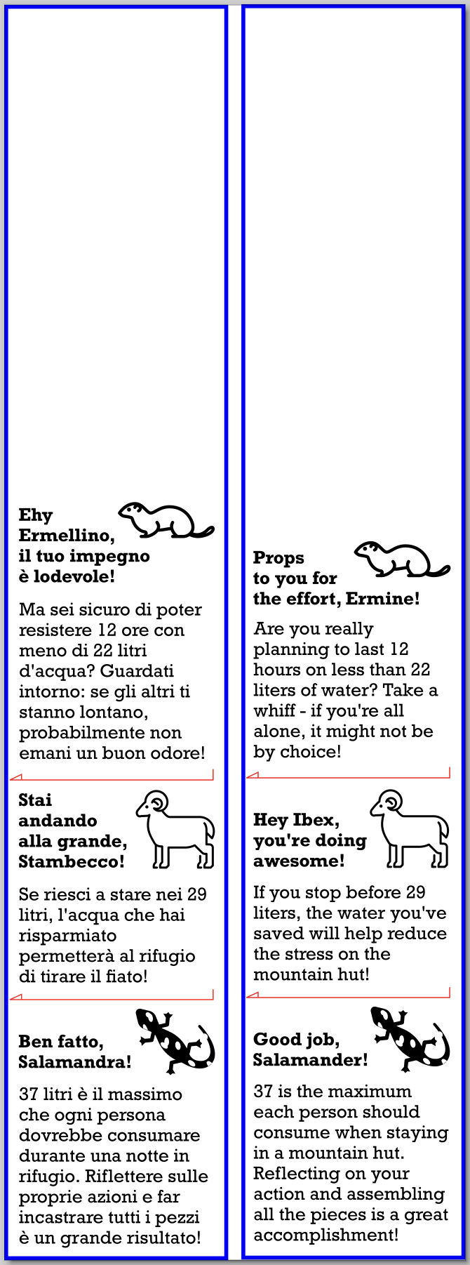
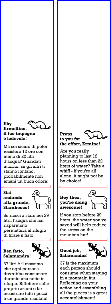
- Animal text descriptions
Scored parts:
- Hexagon lines
- Arrows
Before starting the cuts for the final pieces, test the cut/score/engrave methods on the material to ensure the laser cutter's speed and power produce the expected, pleasant results. Print Gameboard Frame_ActuationBoard.svg, LEDdescriptions.svg, and FW_Gamebox_Topo.svg.
Note: The game title is available in English and Italian. If you want to translate it into another language, edit the file called LEDdescriptions.svg. Use the same laser cutter for the entire box to ensure the kerf remains consistent and the pieces fit together easily. The thin frame around the actuation board is delicate, and it will be needed later, so be careful.
Glue Up Game and Actuation Boards
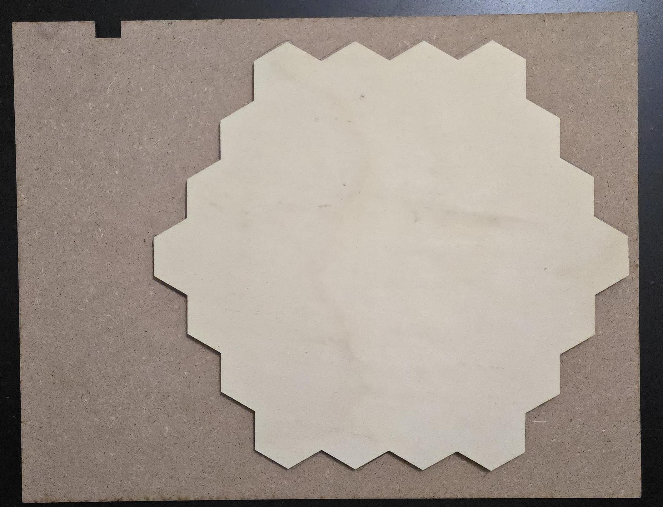
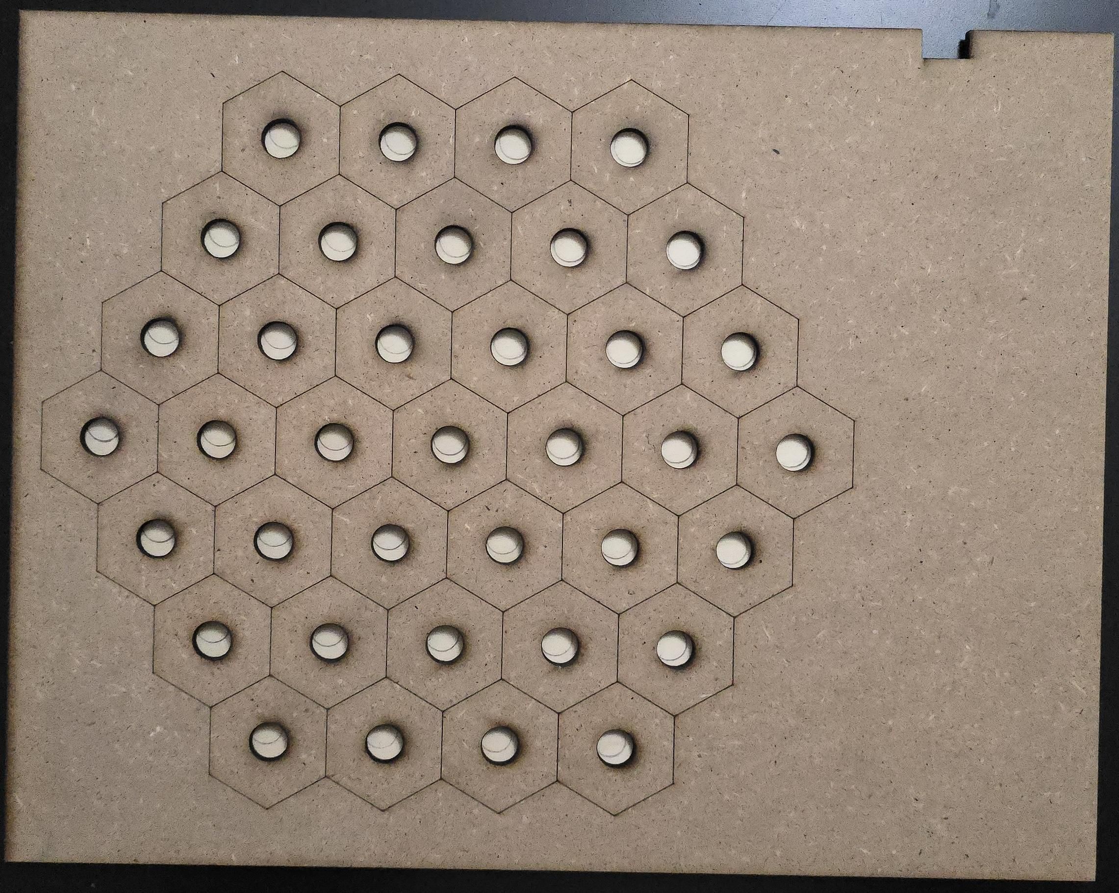

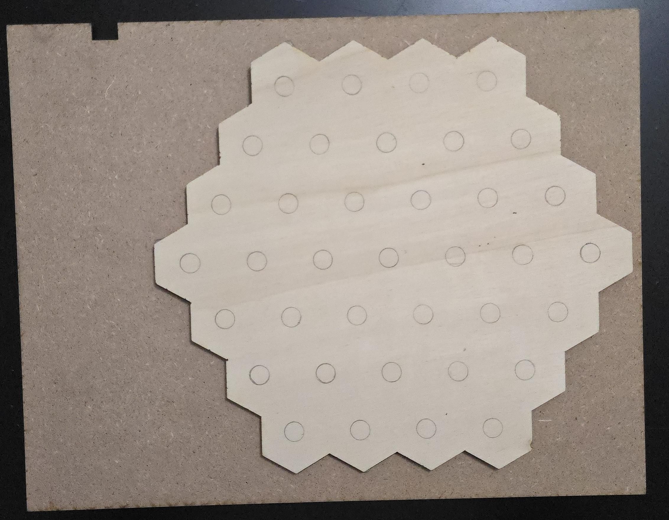
Place the actuation board on the underside of the game board to cover the holes. Once the holes are covered, flip both pieces of wood over without letting them slip, take a pencil, and trace each hole. Flip the actuation board over so that the pencil traces are visible when you are looking at the bottom of the game board. Test the hole alignment with a pair of magnets and make sure that the magnets can move and are mostly centered.
Once a few holes have been tested for alignment on the actuation board, draw the outline of the actuation board on the underside of the game board. Remove the actuation board and add glue to the underside of the game board between the holes, tracing where the score lines on the top side would be. Match the actuation board trace to the bottom of the game board, then press it evenly. Set it on a flat surface, place a couple of heavy books on top of the freshly glued game board to keep the pieces in place, and let the glue dry overnight.
Refine, Assemble, and Seal
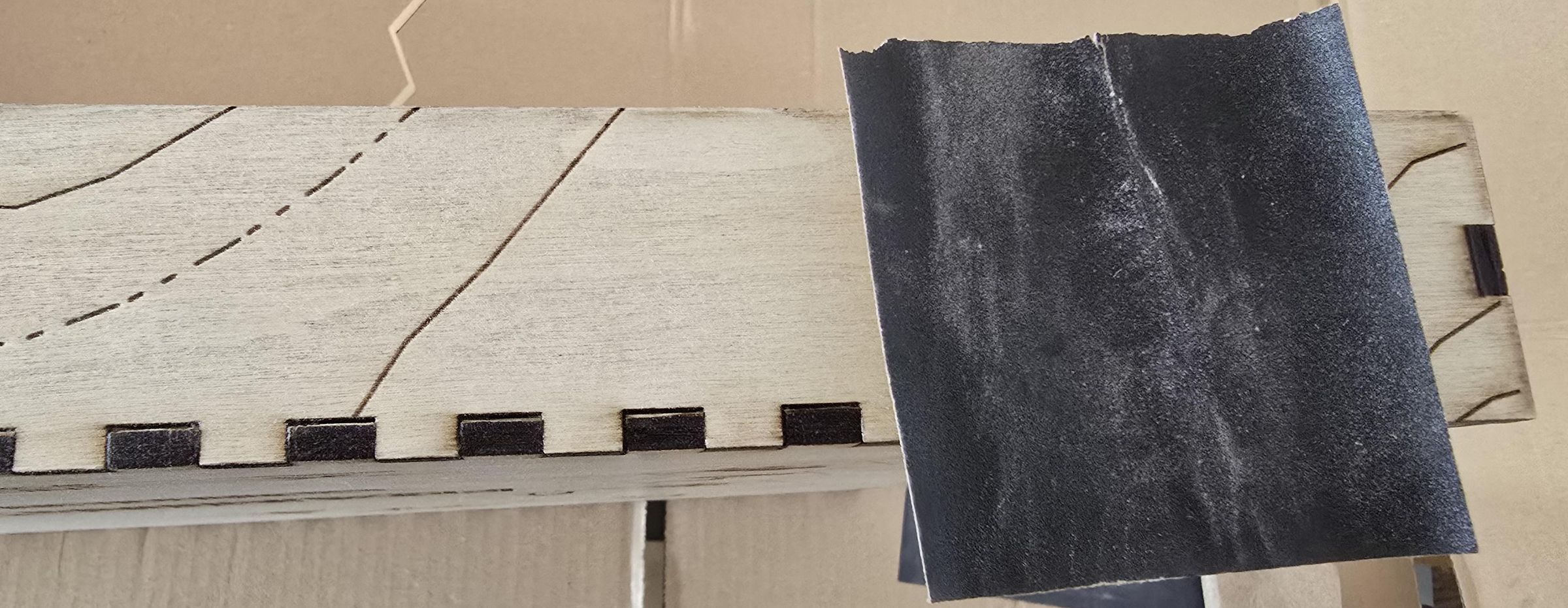
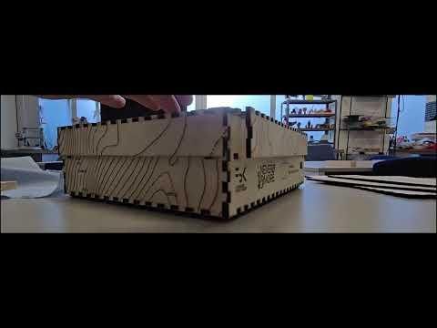
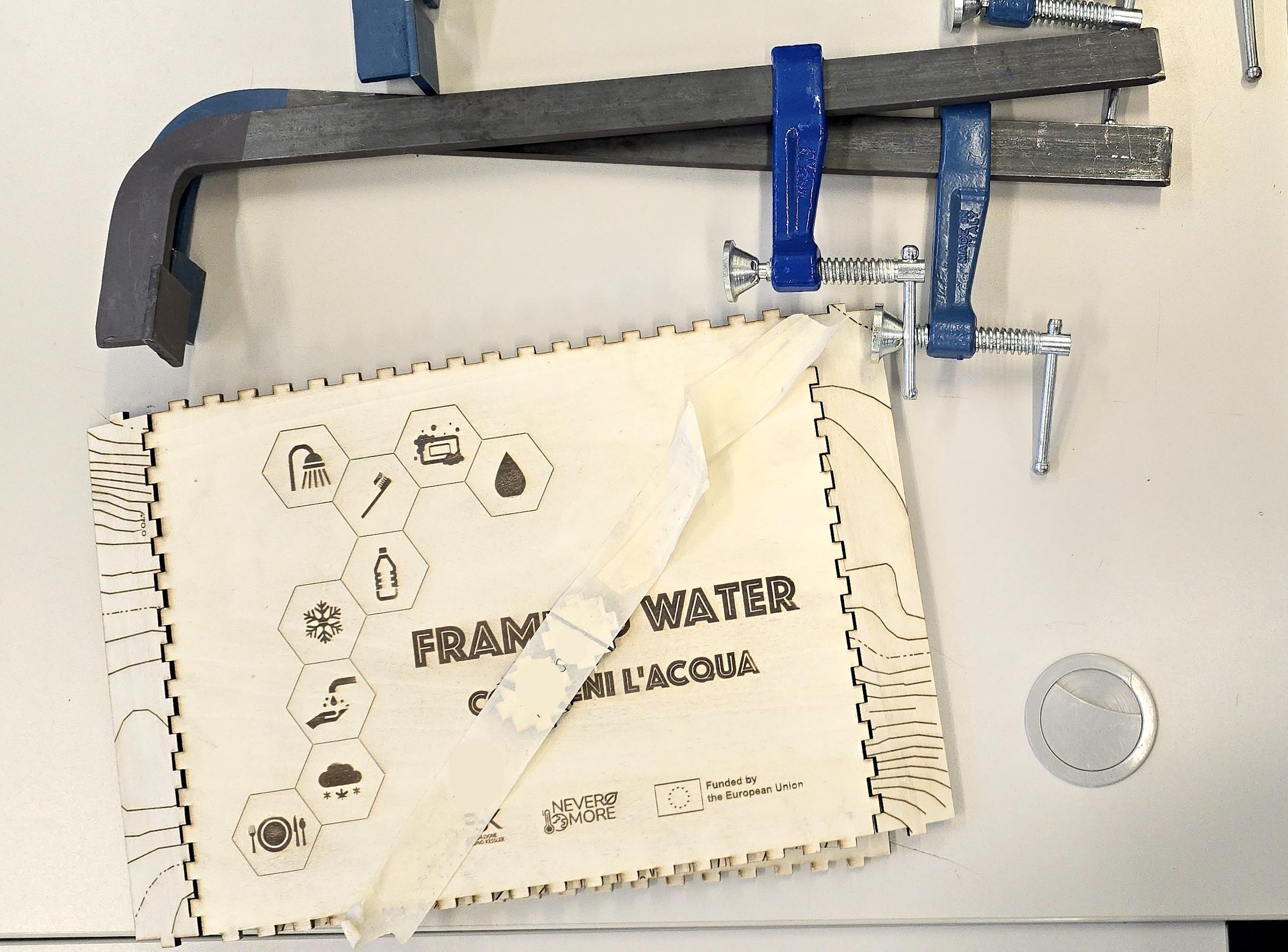
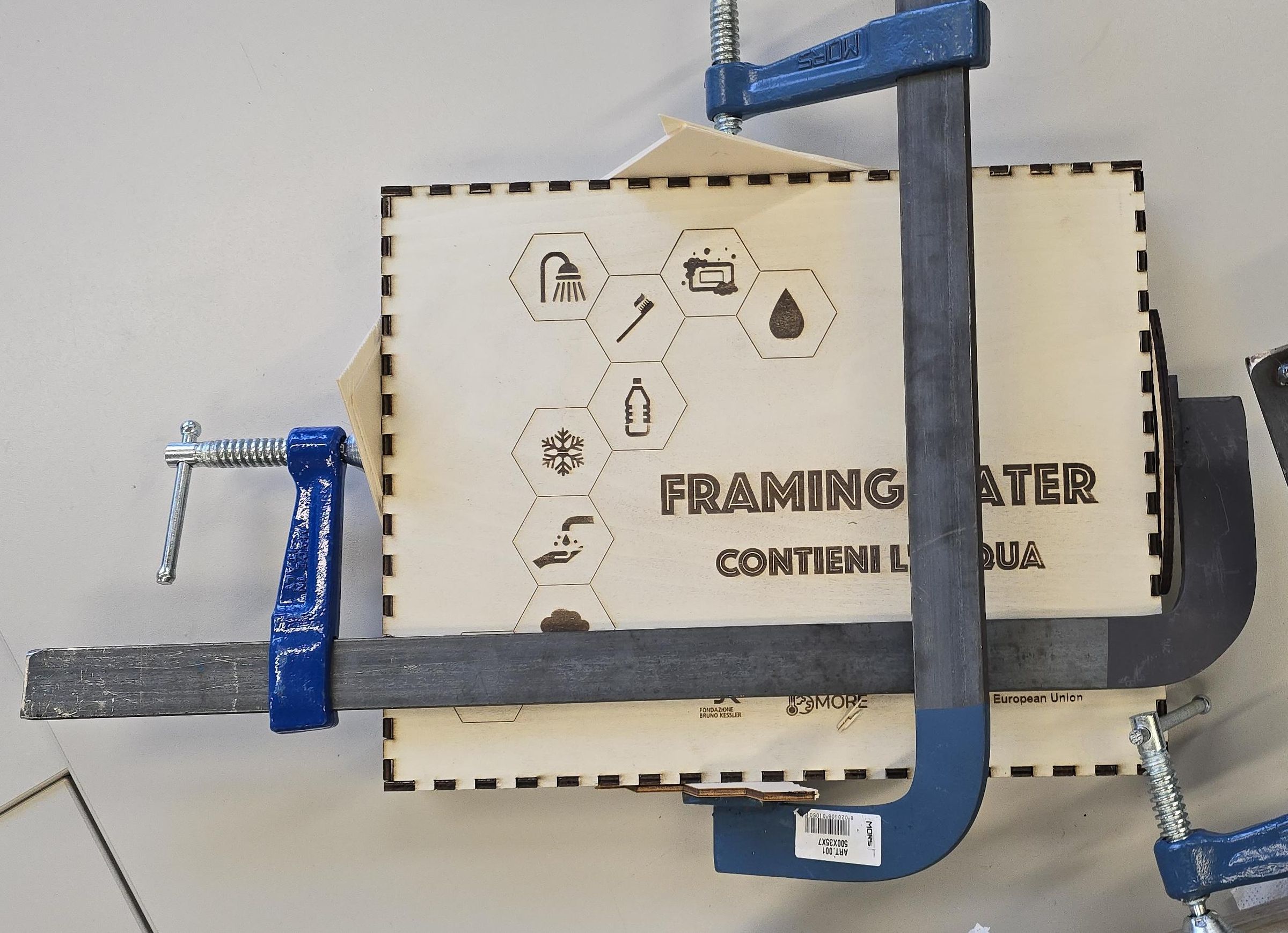
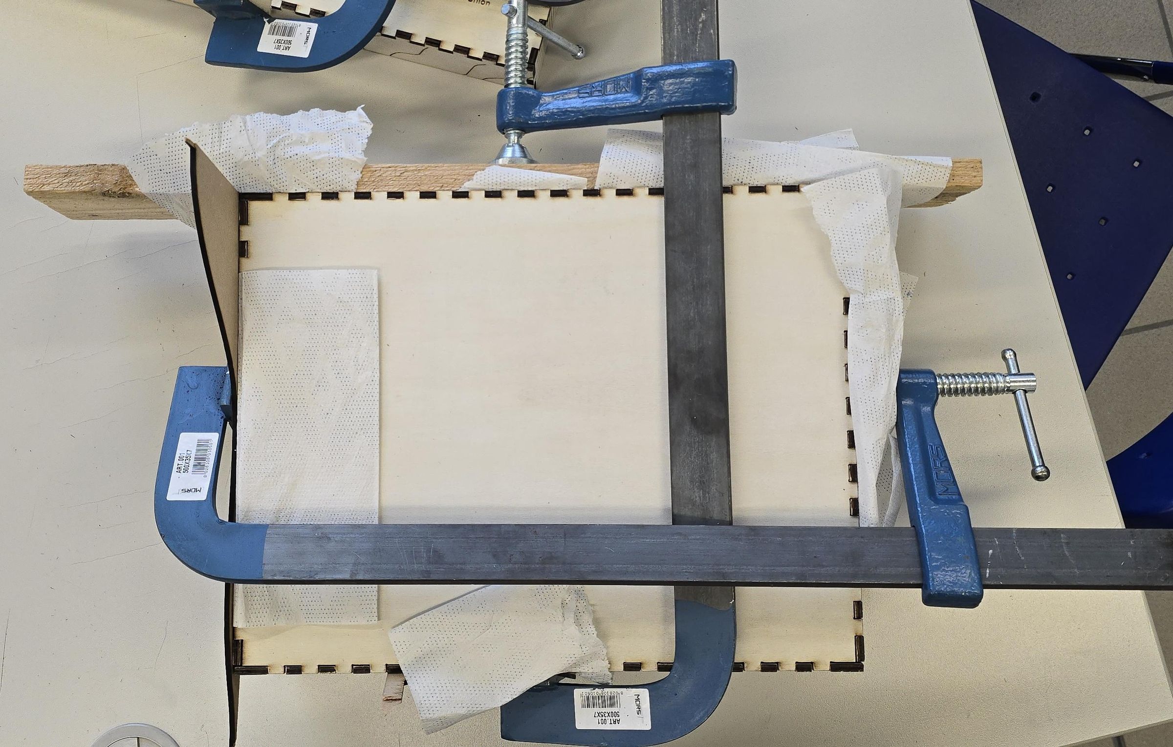
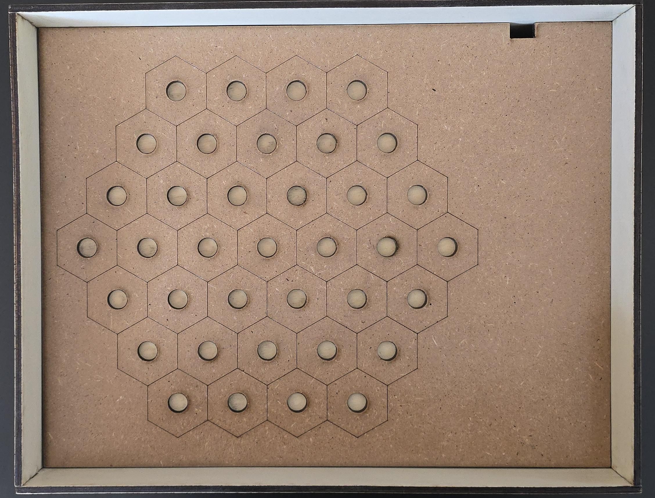
After all the wooden pieces have been laser-cut, it is time to sand off any excess carbon. Check for any rough spots or parts that are darker than desired, and lightly sand the pieces as needed across all printed parts.
The box base is composed of 9 pieces:
- 4 triangular support pieces for the box interior
- 2 short sides
- 2 long sides
- 1 bottom panel
The box lid is composed of 5 pieces:
- 2 short sides
- 2 long sides
- 1 lid with title and graphics
Lay the box base and lid on a large table, as they will be assembled there. On the game box, test the finger joints by gently pushing them together. If the joints are too tight, sand them a little at a time until the fit is secure and even. Once the joints fit together with a little force, apply the general-purpose vinyl adhesive and carefully, but quickly, paint the joint surfaces that will meet. Wipe away any excess glue so that only the desired parts are glued together. Finish the assembly using the rubber mallet to ensure aligned sides and a secure box.
When the box and lid are glued up in place, add the F-clamps in at least two directions. Use some scrap wood between the box and the clamps to maintain even pressure and a better finished product. Leave the box and lid to dry with the clamps on for at least 24 hours or as the glue dictates. Remove the clamps and scrap wood from the project, and set up an area to apply the sealant.
Once the game board glue has dried, the playable surface can also be sealed.
Paint a thin, even coat of the sealant to the outer parts of the game box, lid, frame, and playing surface of the game board. Follow the product drying guidelines. After the first layer is dry, run your hand across the sealed pieces; if the wood feels rough, very lightly sand the surface with 1000-grit sandpaper. After sanding, use a dry towel to wipe up the sanding debris. Apply another coat of sealant and repeat sanding and sealing as necessary.
Once the sealant is dry on the game board and the frame, carefully align the frame around the larger hexagon of the game board, then use the strong transparent adhesive to secure the frame to the game board.
Check the fit of the box lid and base, and the game board within the box base, to ensure an easy fit, and sand as needed.
Note: Do not sand the frame if you can help it; it is too fragile. This prototype has 3 coats of sealant.
Glue Magnets to Game Pieces
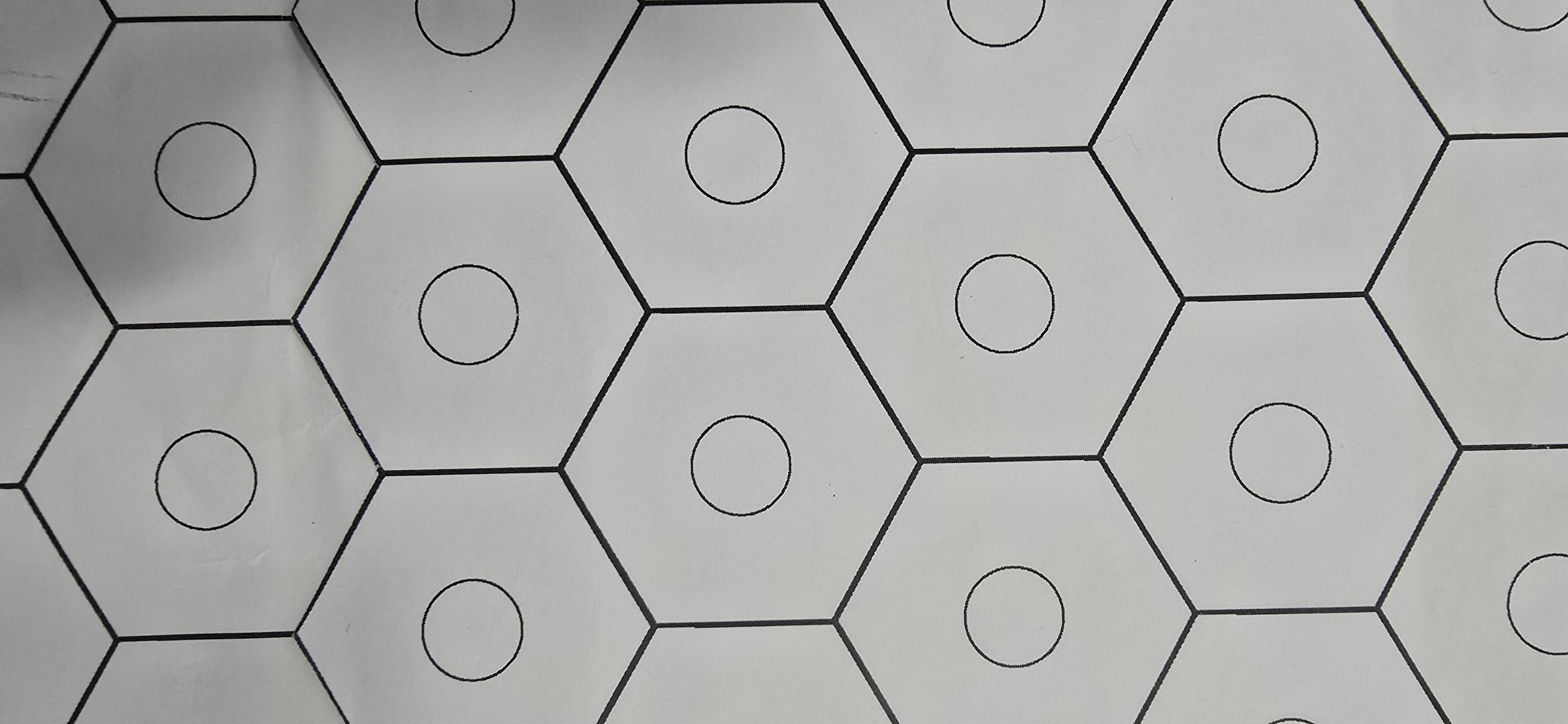
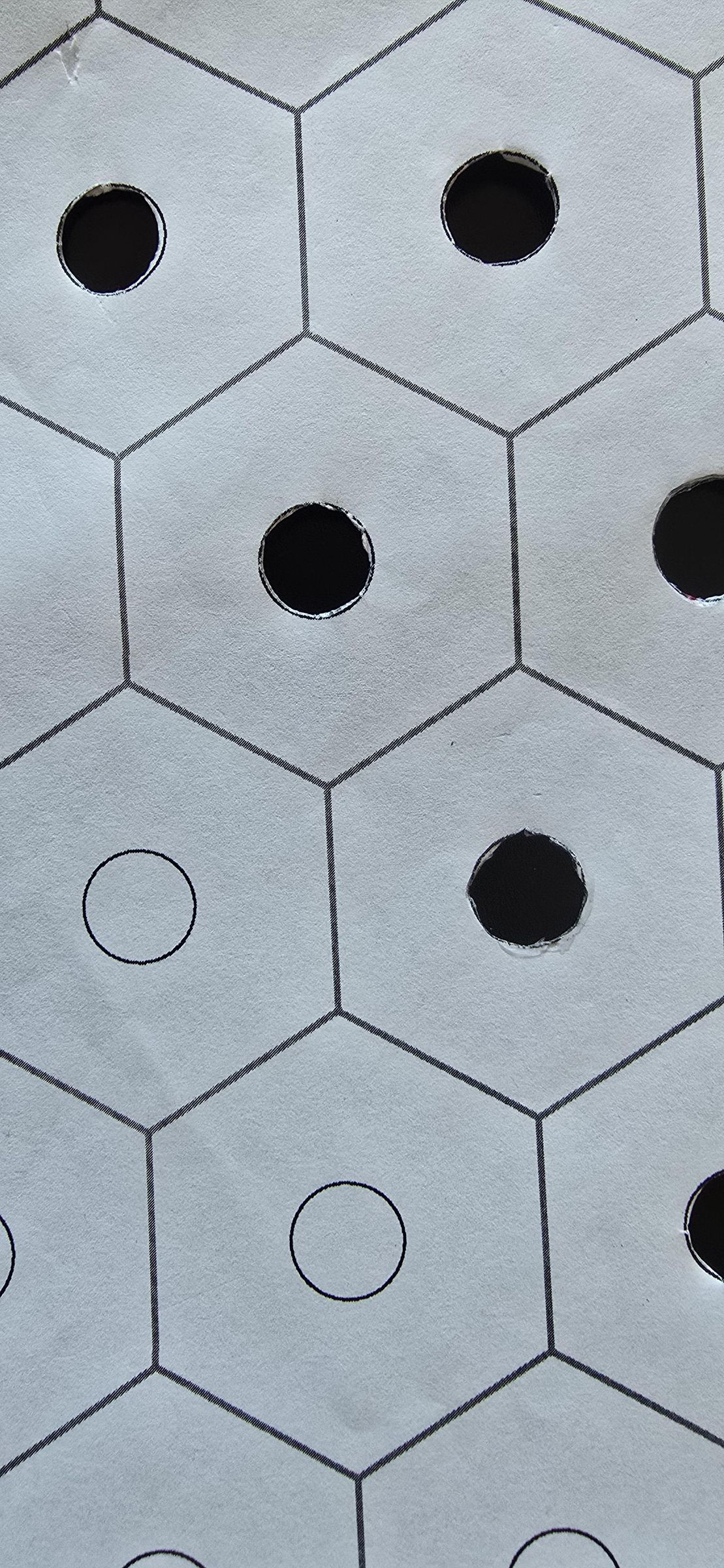
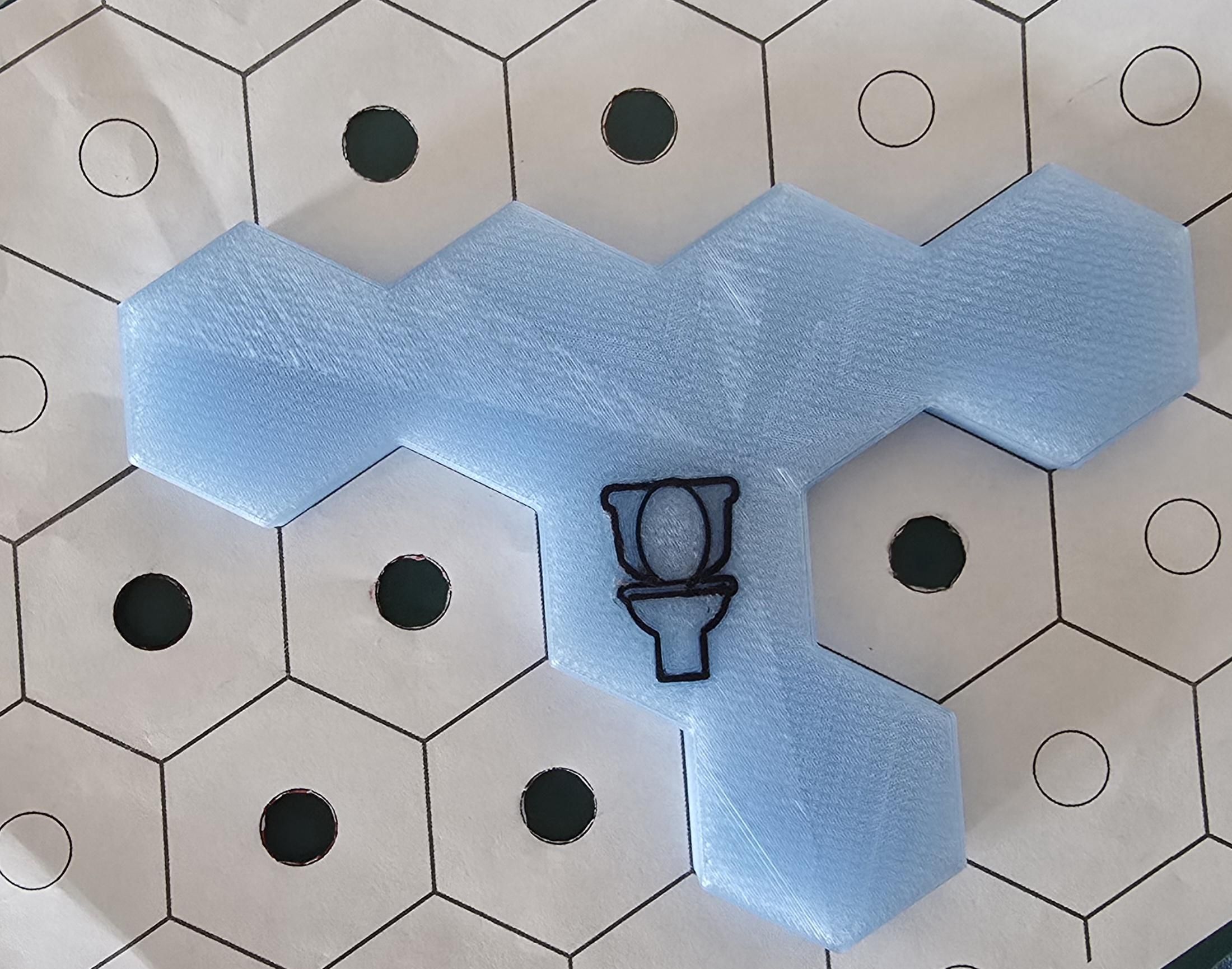
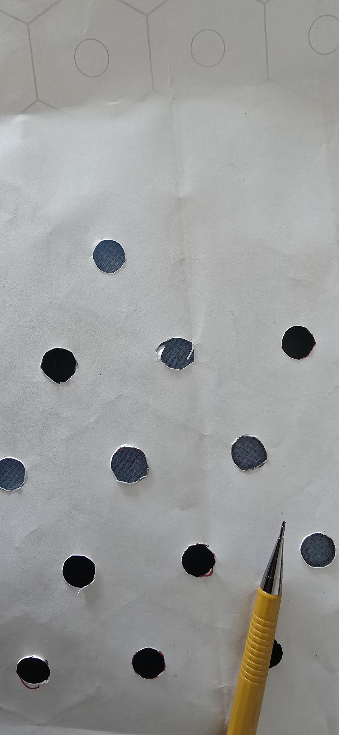
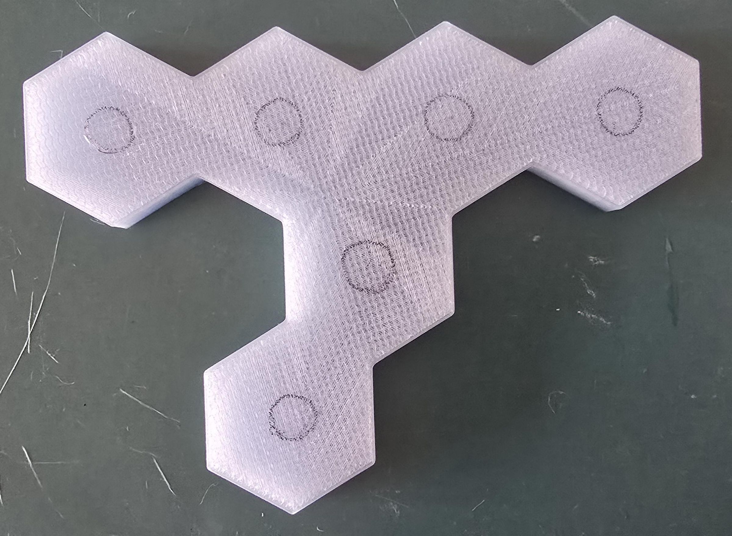
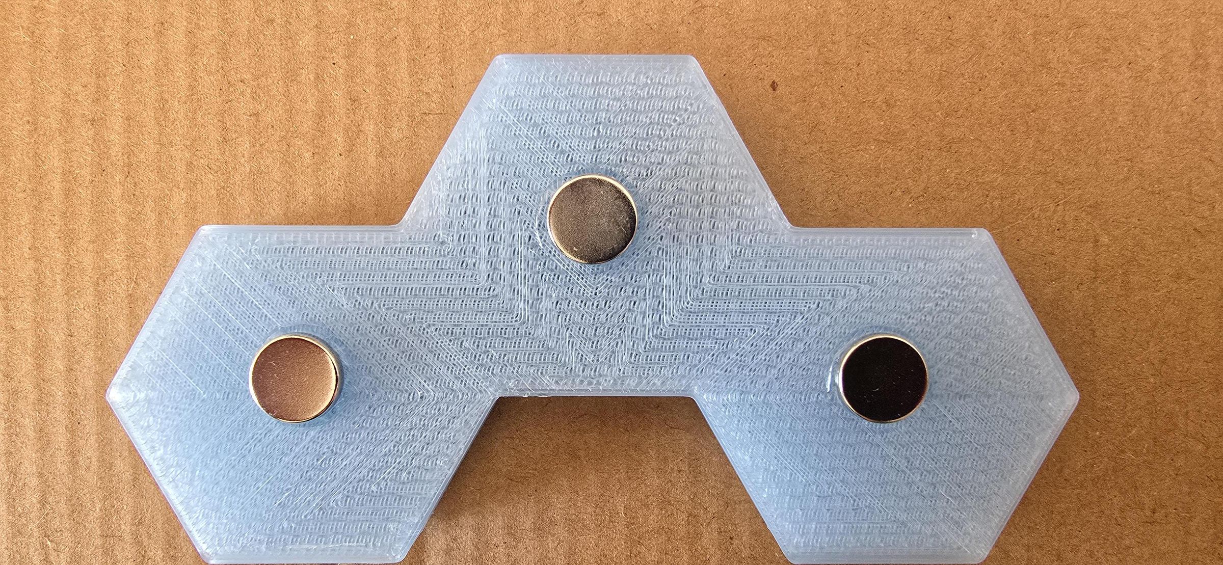
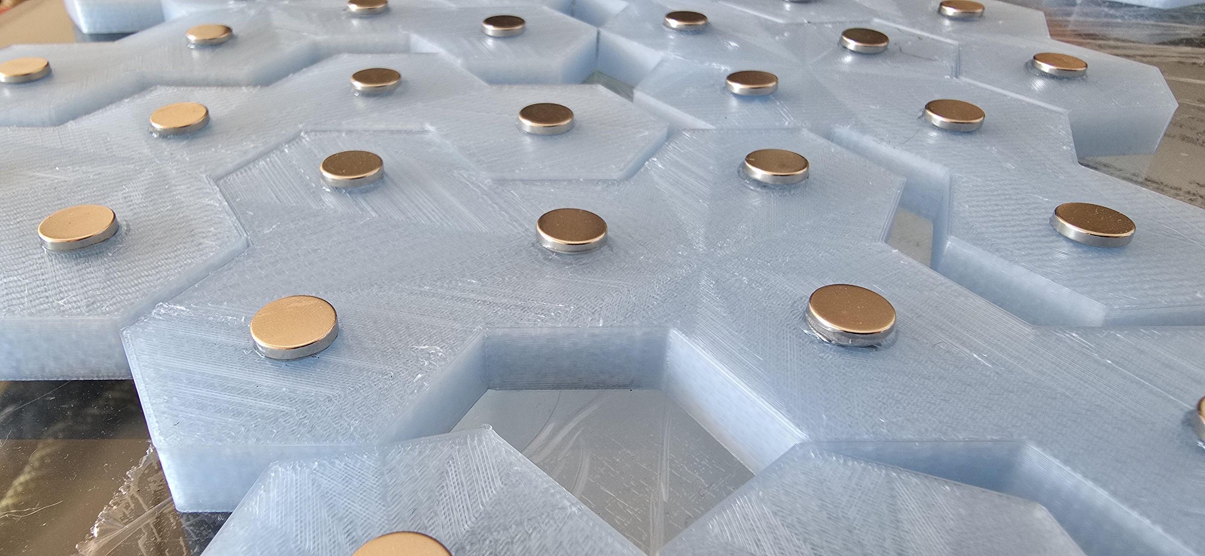
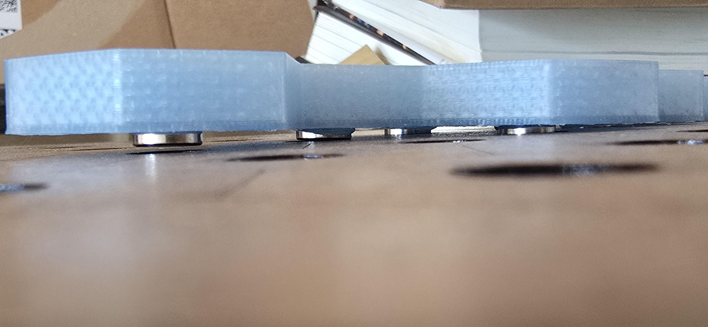
Once the pieces fit as desired, it is time to glue the magnets to the bottom of the game pieces.
Pieces will have as many magnets as the hexagons composing them are. Moreover, the magnets should align with the exact center of each hexagon that comprises a piece.
A copy of the MDF_Gameboard file from Step 3 can be printed at scale on paper to serve as a guide for gluing magnets to the center of each hexagon. With the paper copy in hand, cut the holes at the center of the hexagons to create a template for magnet placement. The pieces need to be matched to the paper outlines, and then the holes traced in pencil on the underside of each piece. The holes in the paper are 12mm in diameter, and the magnets are 10mm in diameter, so they will fit inside the holes with a little play. This step requires some precision to ensure the pieces rest with the magnets nested in the holes of the game board.
With the holes traced, it is time to glue the magnets in place. Ensure the same magnetic polarity faces the adhesive on all puzzle pieces, as this will be important for switch actuation later. Then, use the strong, multipurpose, transparent glue to add a small dot slightly smaller than the traced circle, and firmly push a magnet into the center of each hex.
Once the adhesive has cured, it is important to check that the magnets fit into the holes in the game board. This is done by placing the pieces on the board and observing the fit, allowing a small amount of play so each piece can move slightly to make space for additional pieces during gameplay.
Note: When working on the larger pieces, it might be necessary to glue the magnets in shifts so that they don't create a magnetic force field stronger than the glue and rip the magnets off the pieces, creating a glued column of magnets. Additionally, follow the drying time instructions for your chosen adhesive to ensure the strongest bond.
Create Actuation Contacts
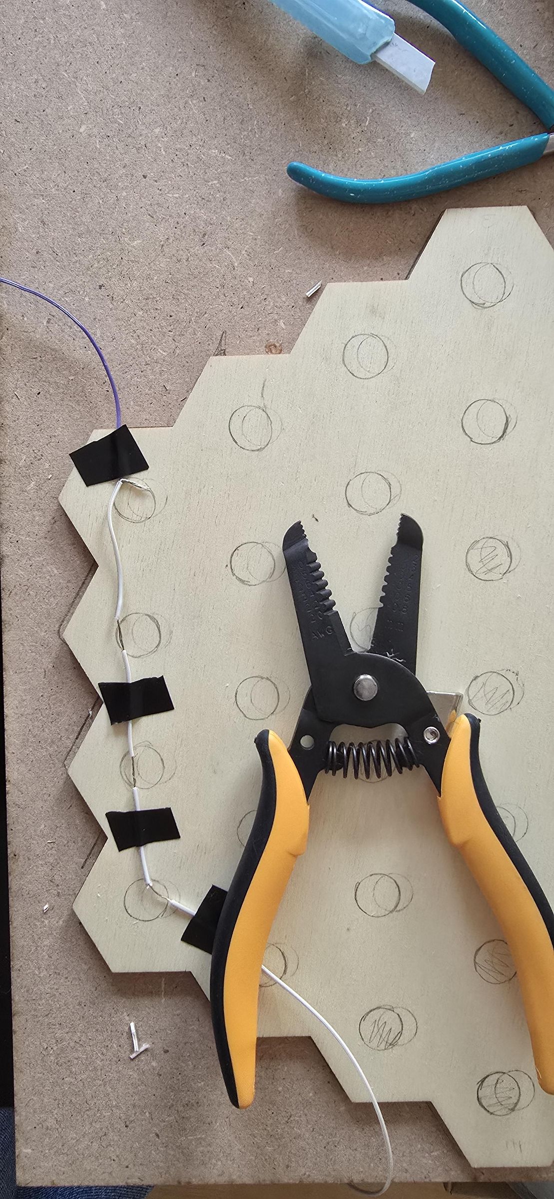
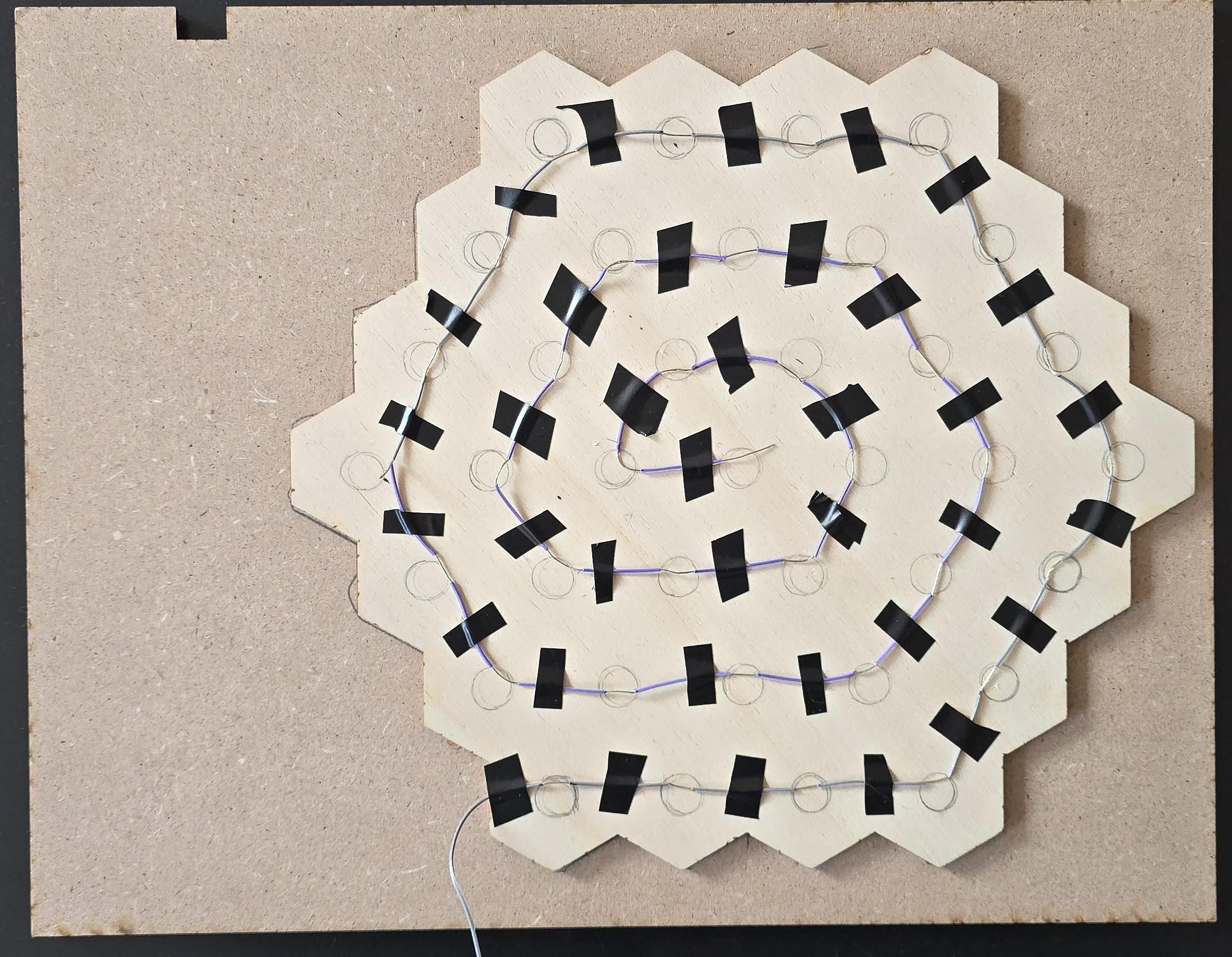
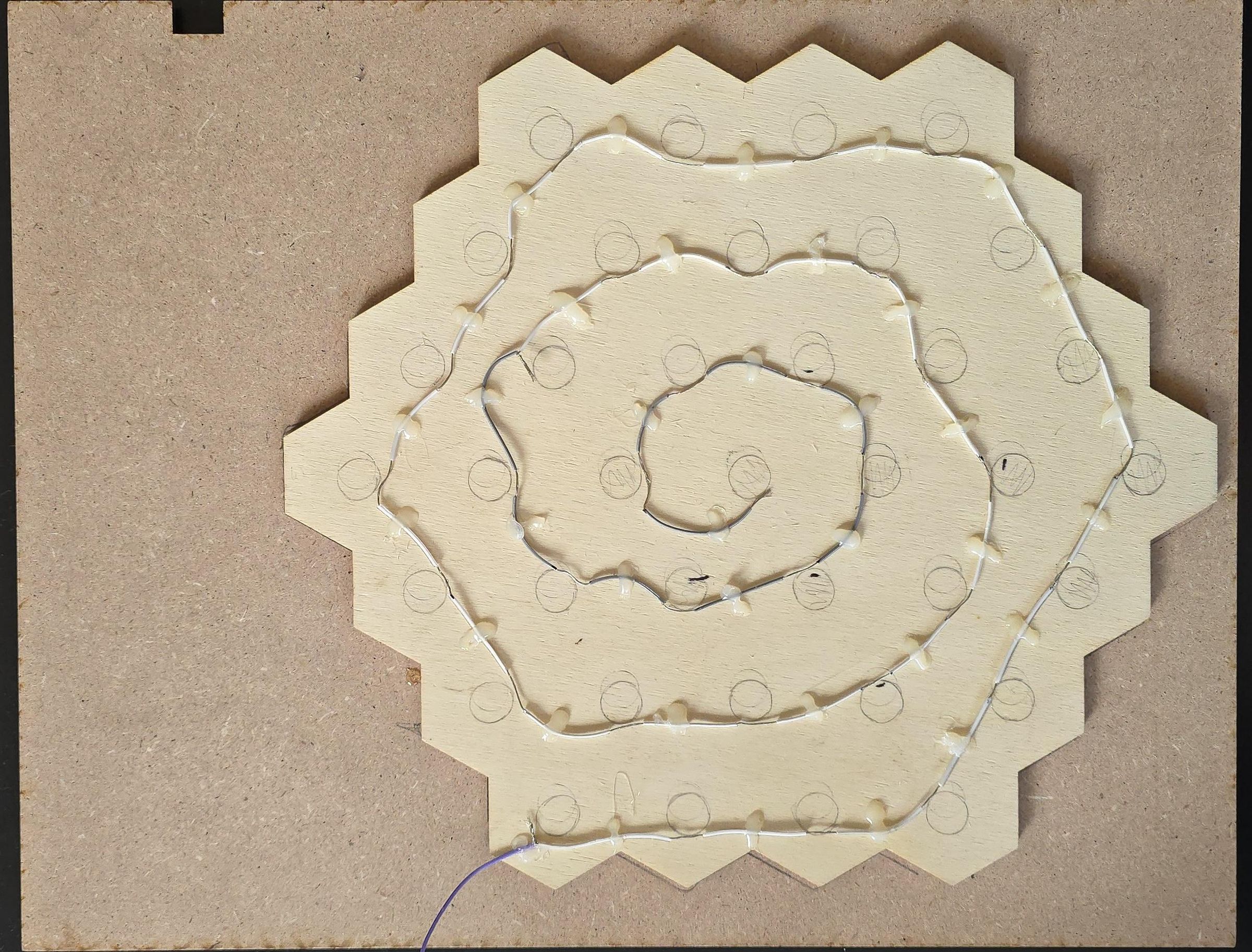
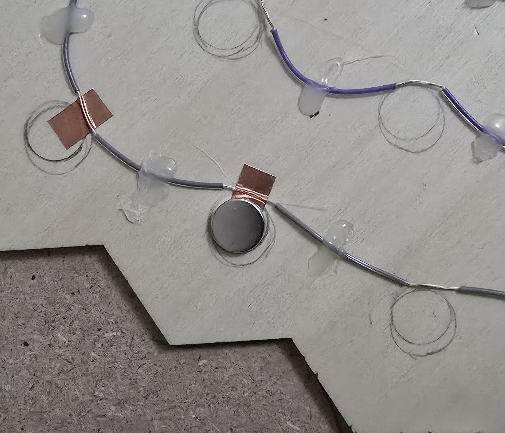
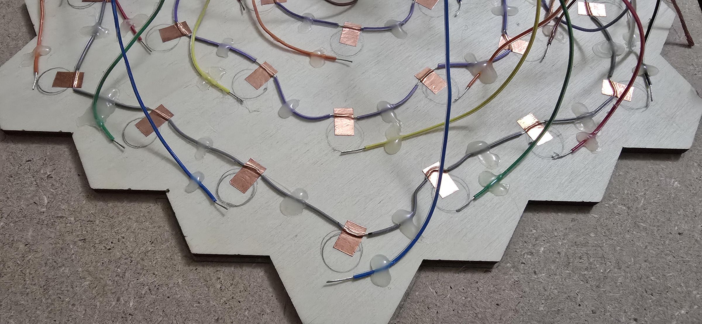
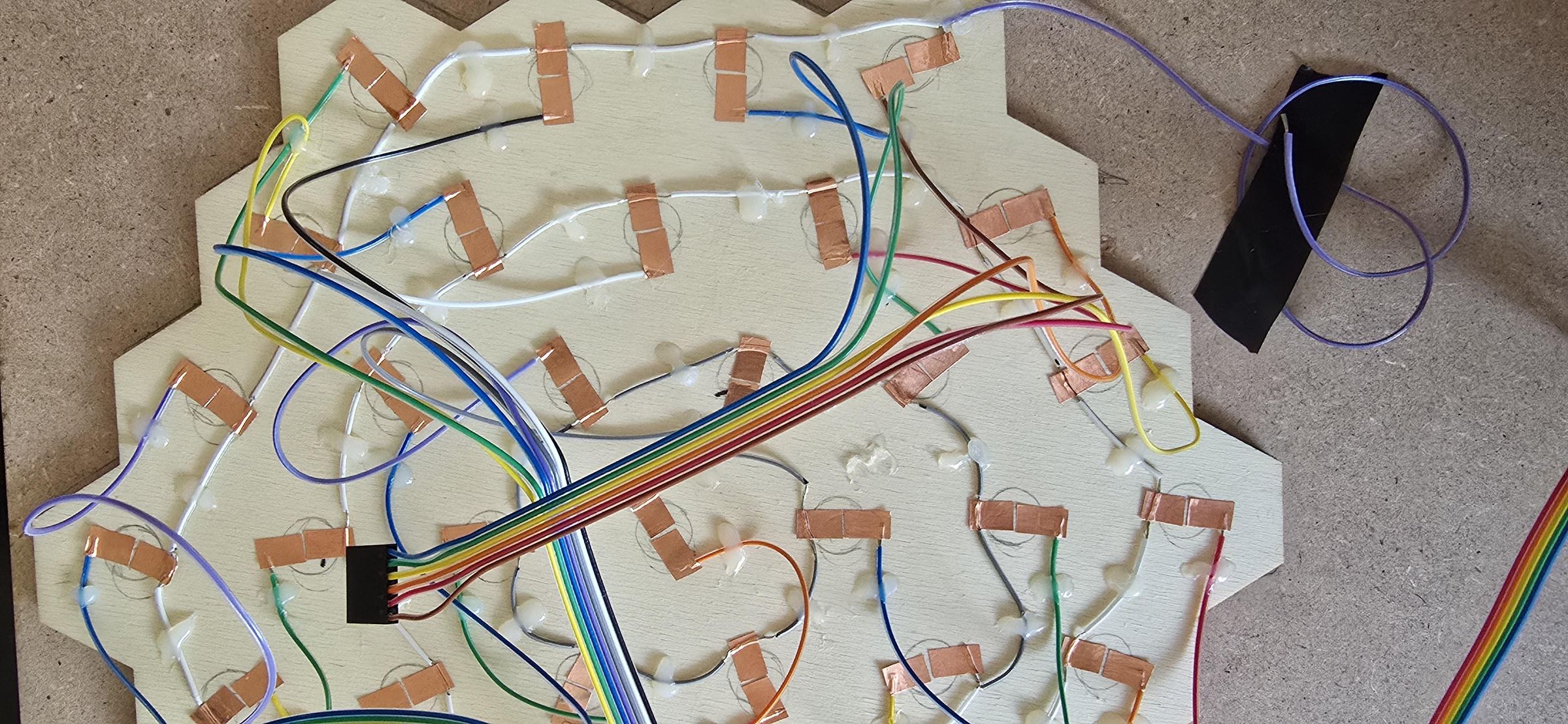
With the glued-up game board face down and the actuation board face up, it is time to create the contacts on each of the 37 holes previously outlined. The contacts will all share a single ground wire, and each hole will have two copper-tape contacts: one for ground and one for data.
Start by taking a single 160 cm length of wire and strip about 4 mm from the very end. This wire will serve as the ground wire for all contacts. Place the bare wire near the central traced circle, then tape it in place. Work in a spiral outwards from the middle. For the next contact, lay the wire on the outer side of the contact, strip 6mm of the sheath from the wire, tape it in place, and repeat for all contacts.
Once the sheath has been stripped back for each contact, check the placement and hot-glue the wire in place. The open ground wire should be placed a few millimeters outside the traced circle. For each contact, cut 2 pieces of copper tape, each 1cm long. One piece will be used for the ground wire, and the second will be used later for the data wire. The copper tape needs to be placed so that one end is almost at the center of the traced circle, then pressed to the board and over the open section of the ground wire.
Each contact needs a second wire connected to its own data pin on the Arduino. To make it easier to manage cables, it is best to use ribbon cables and keep them grouped. Count out the groups you want to make, 5 or 6 wires in a grouping, make it easy to flex the wires, and keep them organized. In the end, you will need groupings that equal 37 wires for the 37 contacts. With your wires and groupings identified, cut 50 cm of wire, then cut that 50 cm in half to get 2 equal-length pieces, called piece A and piece B. Reserve piece B from each grouping for later. It is helpful to match the colors and groupings later in case troubleshooting is needed. This will also make working with Arduino and placing everything a bit easier later.
Take piece A from one wire group, separate all the wires on one side of the ribbon for the first 6cm, and strip about 4mm of insulation from the ends. Repeat the process of temporarily tapping the wire in place near the contact circle, but on the opposite side from the ground wire. Also, repeat the process: temporary placement, hot-gluing the wire near the circle, and placing the copper tape. Crimp a female solder-free connector to each A piece of wire after they are attached to the actuation board, and then select the plastic protector that matches the group created.
Note: Placement is important, and it works best if there is space for the tattoo ink cups to fit flush against the actuation board once all contacts are built and wires are in place. Between steps involving electronic components, such as gluing the ground wire or adding copper tape, a multimeter is used to check each wire for continuity and catch and resolve issues before further complexity is added.
Print and Assemble Magnet Actuators
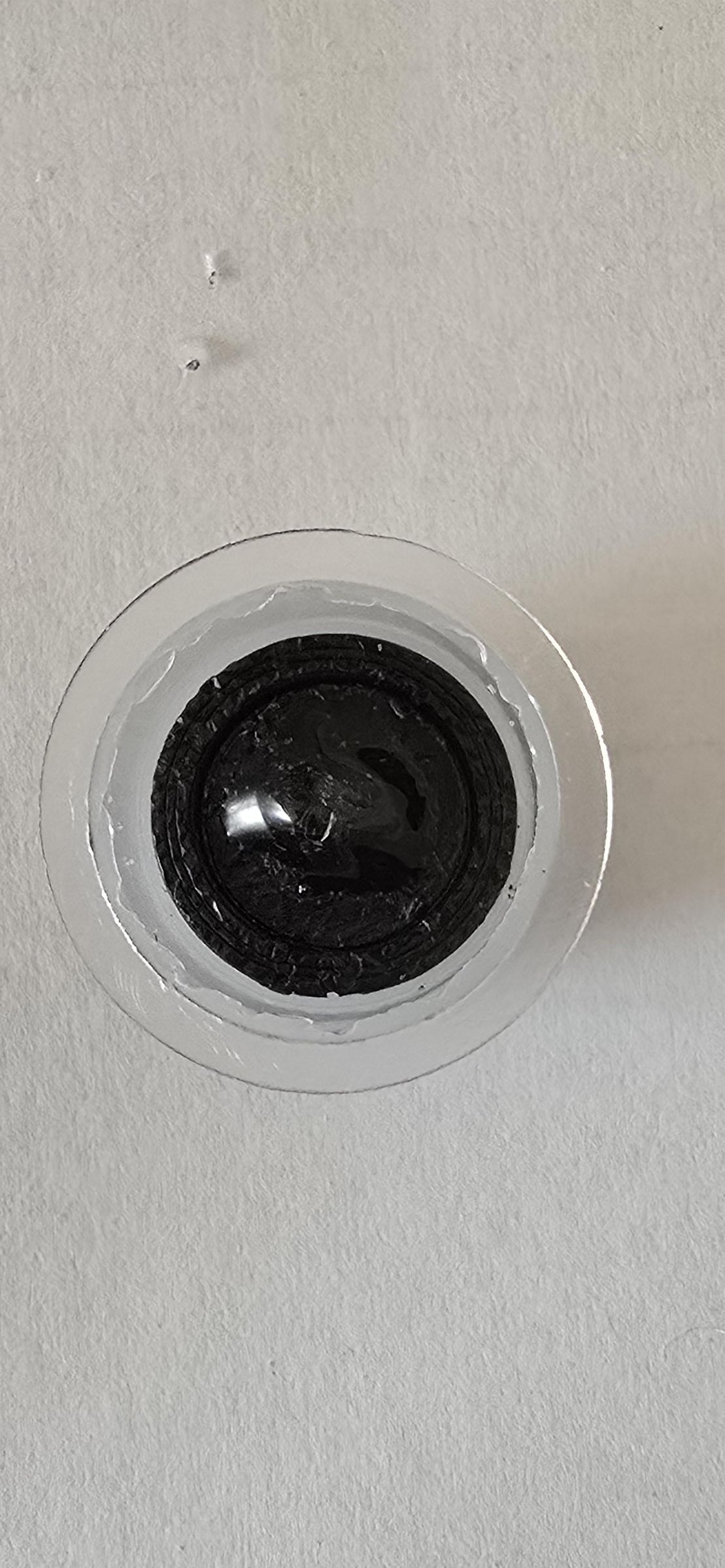
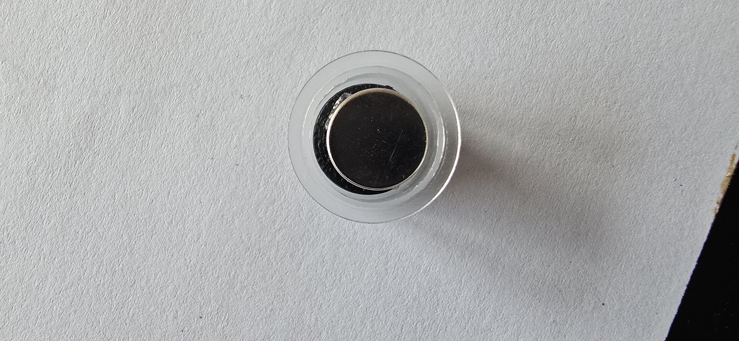
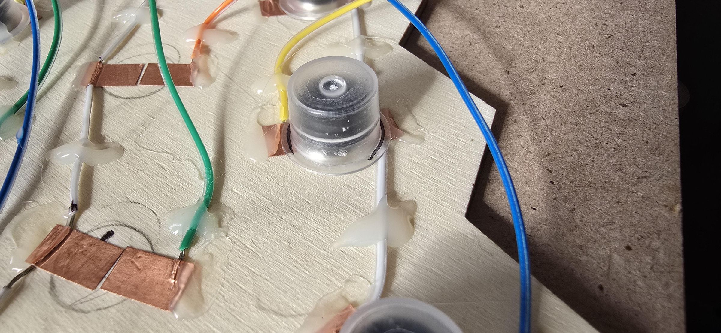
.jpg)
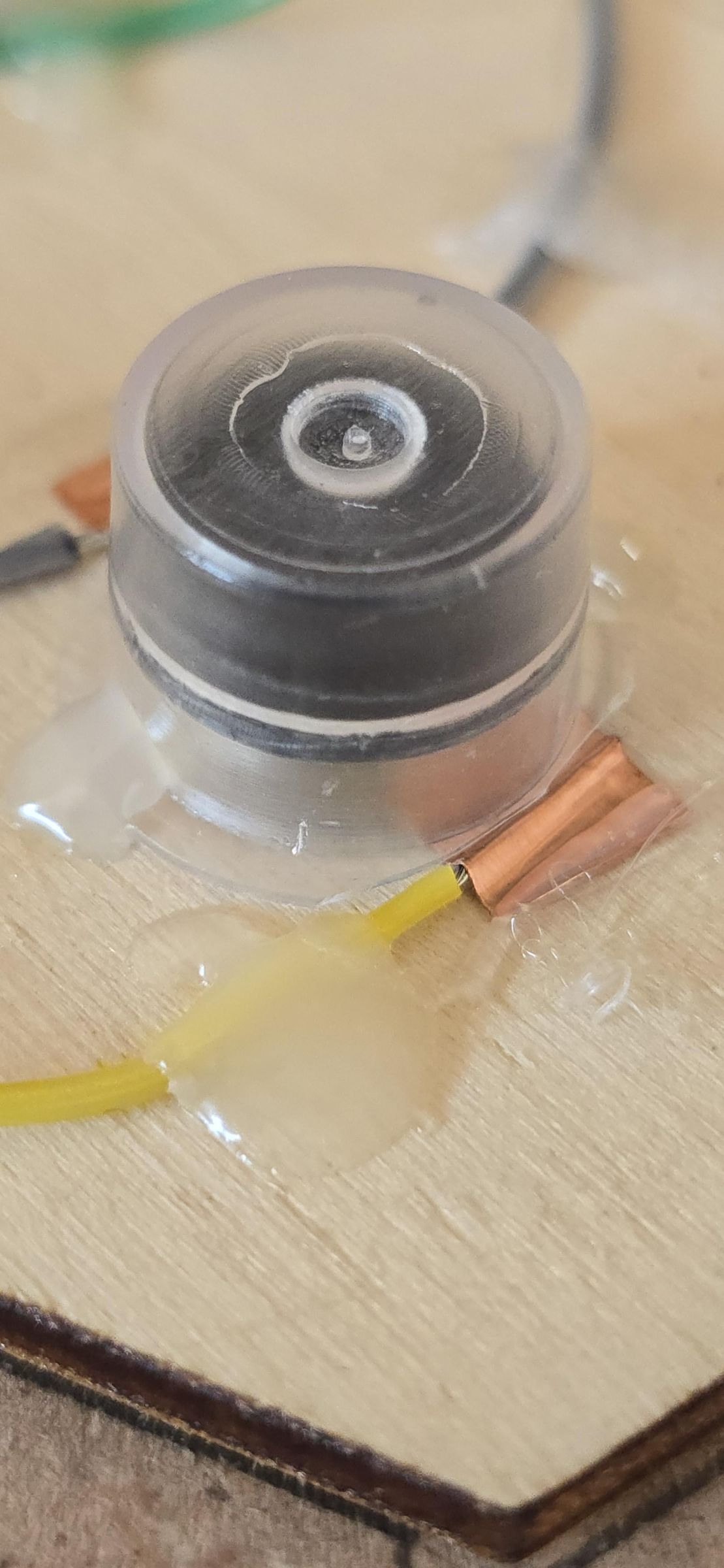
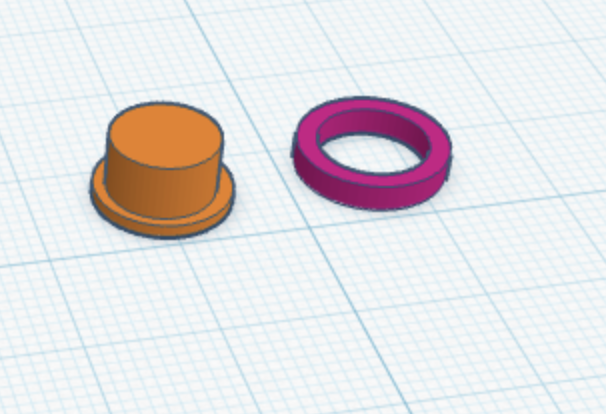
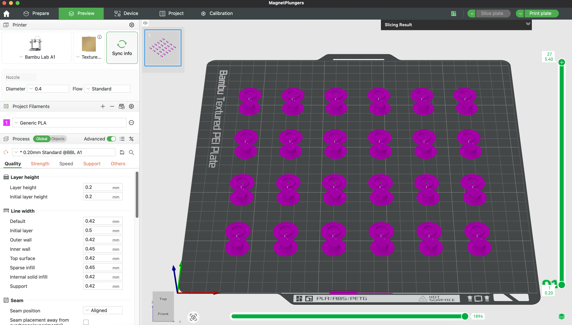
The .3mf file was prepared for a Bambu Lab A1 printer. If you need to make adjustments for other printers outside Bambu Lab, the MagnetPlunge.stl file is available below for further editing. 37 small hat shapes and the rings will be needed for each actuation contact. Once printed, remove the brim and supports, especially the half-dome support from under the hat shape.
These have been created for this specific tattoo ink cup, as it has a 12mm interior diameter and allows the magnets to move freely and make contact with the copper tape.
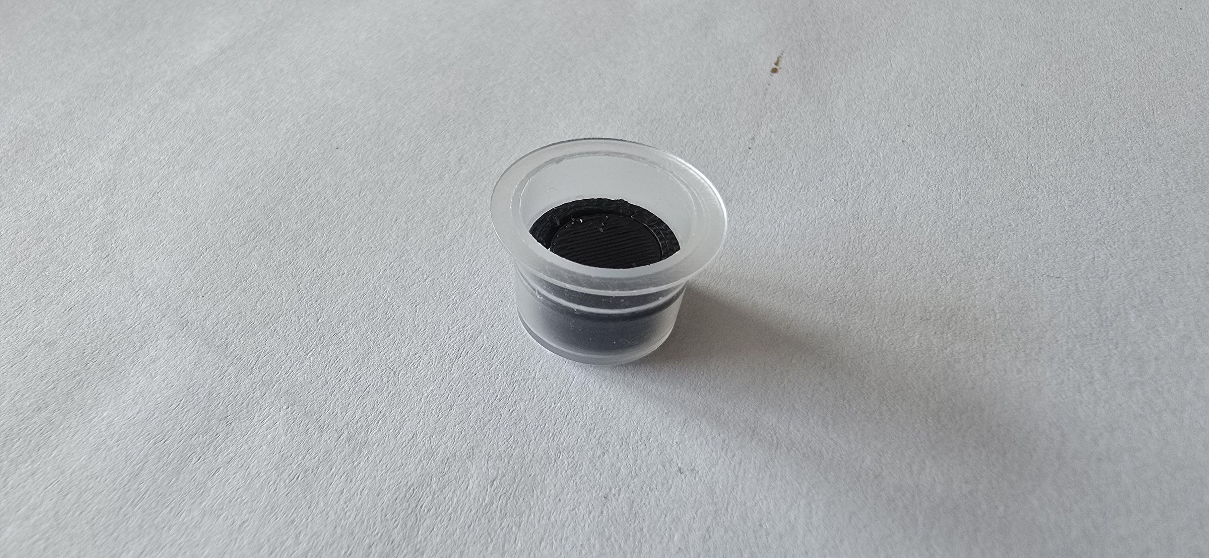
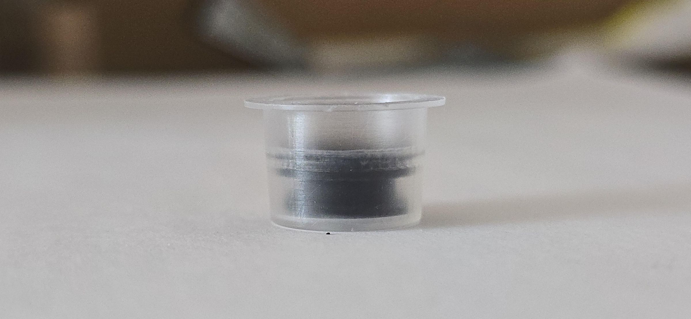
Place the ring over the hat shape, and press the assembly into one of the tattoo ink cups, with the top of the ring level with the cup's midpoint, indicated by the plastic ridge. This part can be challenging to get right, but use even pressure to push on the ring with either the tweezers or pliers. The ring will be tensioned into place by the ridge on the interior of the cup. The correct position is when the hat shape sits flush against the bottom of the cup, and the top is level with the ring after it has been pushed into place.
Identify the polarization of the magnets that would be attracted to the ones previously glued to the game pieces. It is important that the side of the magnet that is facing up in the cup is attracted to the game piece magnet. Place a small dot of the strong, transparent, multi-purpose adhesive on top of the printed hat piece, avoiding the ring, and press the magnet into the center of the cup. Wait 5 to 10 minutes for the glue to set a little, then find a ferrous surface for the cups to dry on. Letting magnets dry in the activated position within the cups helps ensure that the glue doesn’t set the ring and hat in the down position. Follow the drying instructions on your chosen adhesive.
Once the glue has dried, test that each magnet actuator moves freely up and down. Use the tweezers to pull up on the plunger and scrape any excess glue off as needed. To create the best contact, the surface of the magnet should just breach the top of the cup. It is time to add the actuators to the actuation board.
Take one assembled actuator and line it up over each actuation contact created in the previous step. Confirm that the actuator is in the correct position by pressing a game piece into the underside of the board, lining up the holes, this should hold the actuator in place while you hot glue it in place. If the cup doesn’t sit flush against the board, trim some of the brim off and then glue it in place. Continue this process across the board using the game piece to confirm actuator location.
Note: Space out your magnets when drying so they aren’t attracted to each other and undo your work.
Load Code to Arduino
The code for this project is available on GitHub. For the code to function properly, be sure that the wiring matches the electronics diagram in the following step.
3D Print Solderable Breadboard Holder
3D print solderable breadboard holders that will be glued to the inside of the box to secure the board. For this game, two long bars and two short bars were printed to secure the breadboard against one wall of the inside of the box. This file was created for a Bambu Lab A1 3D printer.
Note: There are many available styles of holder available online, pick what works best for you.
Downloads
Assemble Electronics
.png)
.jpg)
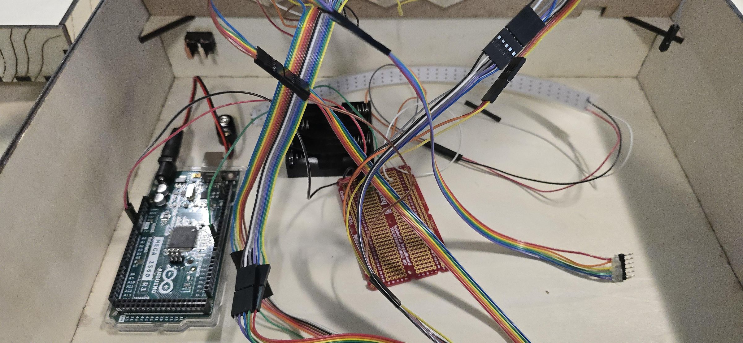
This code depends on Arduino and circuits being wired as shown on this Cirkit Designer.
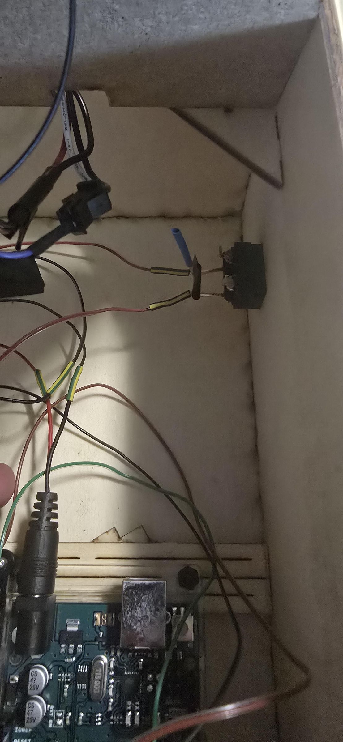
Take the rocker switch off/on, and press into the open rectangle from the exterior of the long side of the box that was previously cut. You may need to gently bend the prongs so they fit into the hole easily, then bend them back. With the multimeter, confirm how the prongs are wired so the rocker switch functions to connect and disconnect power.
Take the PP3 connector to a 1.2 mm barrel connector, separate the ground and hot wire, and cut the hot wire at the halfway point while keeping the ground intact. Solder one side of the hot wire to the previously identified prong and the other side of the cut hot wire to the other prong on the rocker switch. Snap the PP3 side of the connector to the terminals of the 4-cell AA battery holder. Velcro the 4-cell battery holder to the inside of the box so it can be moved to change the batteries.
Insert the barrel connector into the Arduino, and once the position is determined, use double-sided tape to secure the plastic part of the Arduino case in place inside the box.
Cut two pieces of wire 20cm long, one red for power and one black for ground. Using the solder-free connectors, crimp a male connector onto one side of each of the just-cut wires, then place the plastic protector over the connections. Then take the other ends of the wires and the solderable breadboard, and solder them into the corresponding positive and negative channels.
Cut five more pieces of wire 20 cm long. One wire will be soldered to the negative channel and then connected to the ground wire on the actuator board. The legs of one 1000 µF 10 V Aluminum Electrolytic Capacitor, Radial, should be soldered to the board as indicated on the wiring diagram, and power and ground should be supplied to each leg accordingly. Two more wires should be black and red, wired on the other side of the capacitor, and then connected to the LED strip. The final two wires are for the LED strip's digital channel. The last two should have solder-free male connectors crimped to one side. Solder one of the wires in a separate row, solder a 560 ohms resistor on the same row, and solder the last digital pin wire on the same row but on the other side of the resistor.
Plug the red power wire into Vin on the Arduino and the black ground wire into GND. Take the B pieces of wire, strip 4mm of insulation from both ends, and crimp male solder-free connectors to both ends, along with corresponding plastic protectors to match the previous wire groupings. Plug the magnet actuator wires into pins 3-13, 22-46, and 23-47. Plug the data channel wire into pin 2 on one side of the resistor.
Crimp female solder-free connectors onto the LED wires, then connect the power, ground, and data cables. Lace the LED strip to the top of the game board, put the animal descriptions along the far right side of the board, cut a double-sided piece of tape the length of the LED strip, and press it next to the animal descriptions so that the LEDs indicated line up with the description arrows.
Take the 3D printed solderable breadboard holders, placing the breadboard between the two long bars, and hot glue the bottom of the bars pressing the bars to the bottom of the inside of the box. Hot glue the two short bars to the box around the breadboard, securing it in place.
Insert 4 AA batteries into the 4-cell battery holder. Turn on the rocker switch and wait 10 seconds to ensure the Arduino and LED strip light up.
Print Instructions
.jpg)
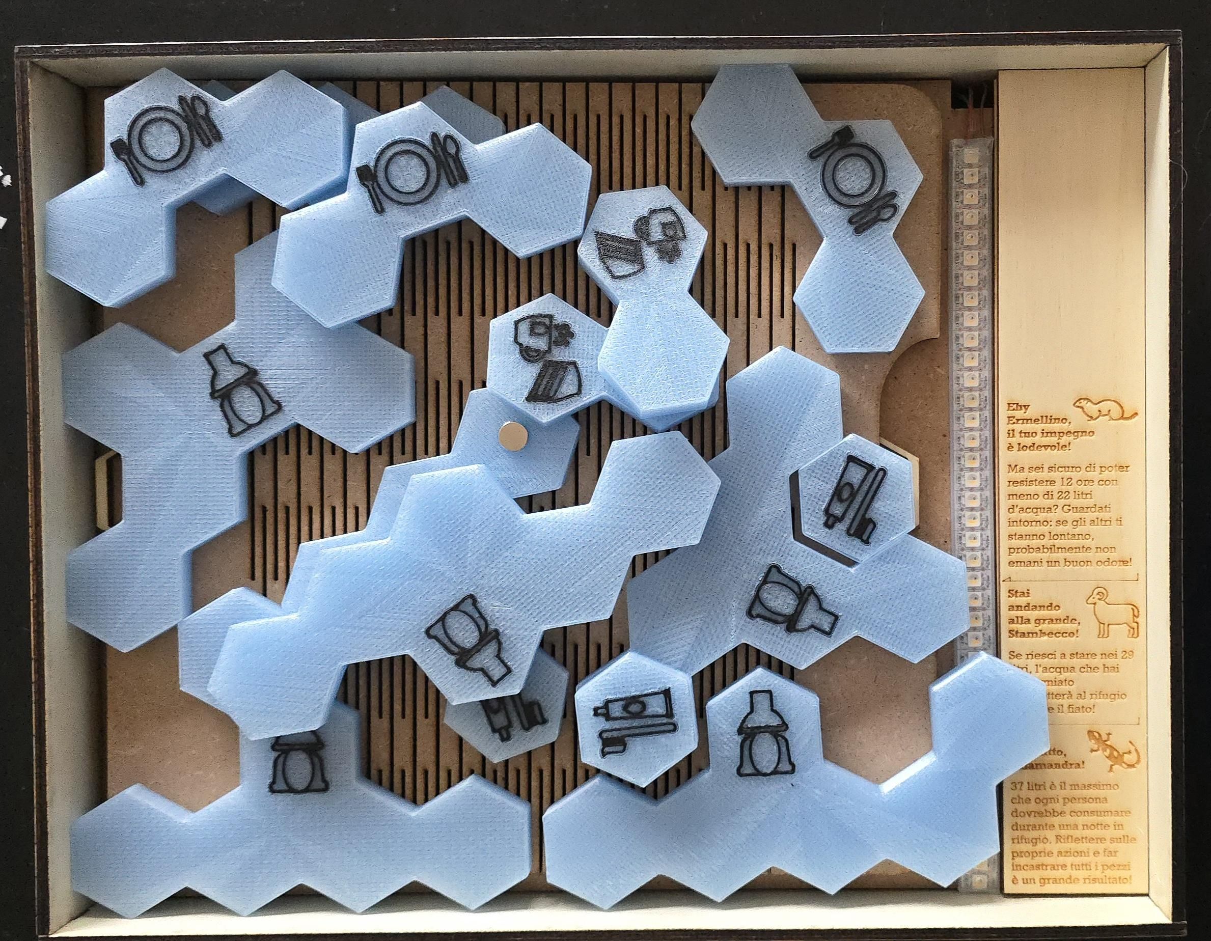
Print the instructions for the game double-sided and fold them like a booklet. Below are options for the instructions in English and Italian.
Note: This page is scaled for A4-sized paper.