Freeform Satellite Sculpture – Sattiny 2.0
by rsappiawf in Circuits > Art
1561 Views, 19 Favorites, 0 Comments
Freeform Satellite Sculpture – Sattiny 2.0


This project is the continuation of an idea that started a few years ago (2020) with Sattiny, a small handmade satellite sculpture inspired by the stunning freeformed electronic art of Mohit Bhoite. His work has been a huge inspiration for many of us who love combining electronics, sculpture, and storytelling — and this second version is my way of pushing that concept a little further.
Since last time I struggled to manage symmetry and consistency with the bent brass wires, I decided this time to go with some additional help. For that, I designed some 3D-printed jigs that helped me hold the different parts in place and also bend the wires correctly so all the parts turned as they were supposed to be without having to struggle with unexpected results. I also wanted to ensure that the process was repeatable.
Sattiny 2.0 keeps the spirit of the original: it’s a purely aesthetic satellite model, built with brass rods, a microcontroller, some LEDs, and a lot of love. But this time, I wanted to make it easier for others to replicate or adapt the concept — even if they don’t have advanced soldering skills or specialized jigs. All jigs can be found under the following link Freeform Satellite Sculpture – sAttiny 2.0 Jigs
That’s why, in this post, I’m not only sharing the finished project — I’m also including:
- 3D-printable tools: Small fixtures to help position rods accurately before soldering. They make the freeform construction process much easier and repeatable.
- Assembly diagrams and tips: Based on what I learned from the first version, I’ve added some improvements to the structure and LED layout.
- Suggestions for customization: The goal isn’t to clone this satellite exactly, but to offer a starting point for your own unique builds.
If you’ve ever wanted to make a freeform satellite of your own — and you have access to a 3D printer and a bit of patience — you’re more than ready to dive in.
Let’s keep celebrating this beautiful, geeky mix of analog craft and space-inspired aesthetics. All credits and respect to Mohit Bhoite, whose artistic vision continues to inspire makers around the world.
Supplies
Components list
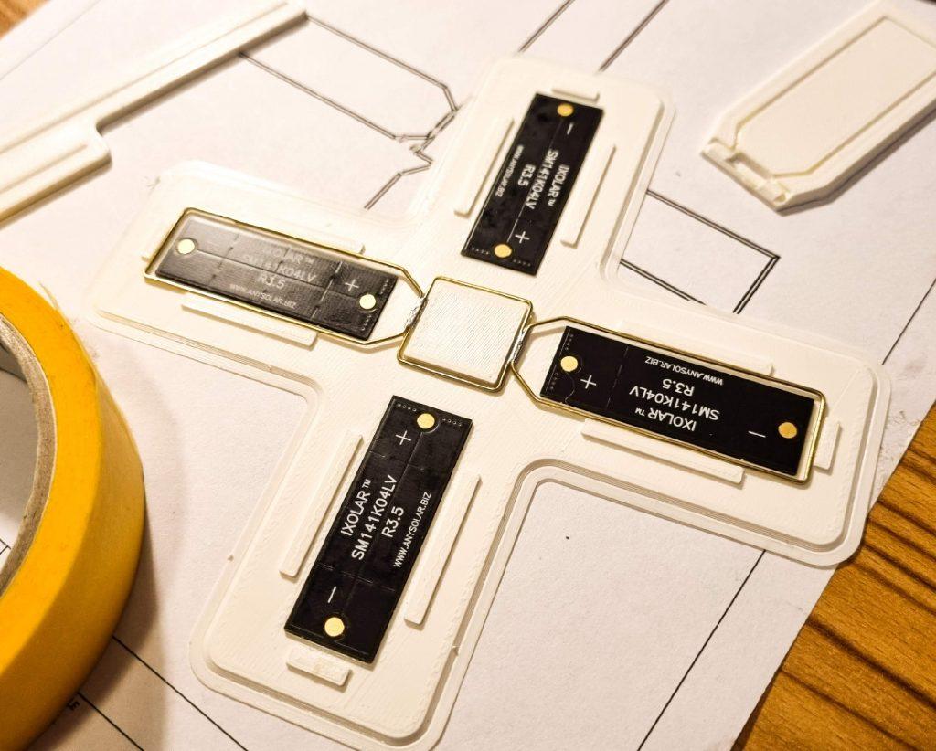
- 4x IXolar SM141K04LV
- ATtiny25V-10OPU
- 1 x 200K
- 1 x 10K
- 1 x 1K
- 2 x 3mm LEDs
- 1 x BAT42
- 2 x 4F Capacitor
- 0.8 Brass wire
The Design Process


As a first step, I draw in OnShape how the satellite structure should look like, having in mind the solar-cells dimensions and the final size I was aiming for. Almost all of the dimensions are related to the solar cells size and implemented as variables so in case a different solar cell form factor is needed it only takes to change two values and the 3D design will update itself to allocate the new cells. I am planning to play with this in the near future and do a micro version variant without having to go through the whole process again. The jigs are also automatically calculated and generated!
A 1:1 PDF is included in my GitHub repo (sAttiny2_0_Panel_Body_Guide.pdf). It can be used as a reference if printed at 1:1 scale.
Jigs in Action


Having the structure of the sculpture as 3D-model, I started to develop the jigs that would help me to go through the building process.
All jigs can be found under the following link: Freeform Satellite Sculpture – sAttiny 2.0 Jigs. This is the first step before starting to build the satellite
Wire Jig


For this project there are three main wire lengths that are needed. To make sure consistency is achieved, this jig facilitate the task of working always with the same lengths.
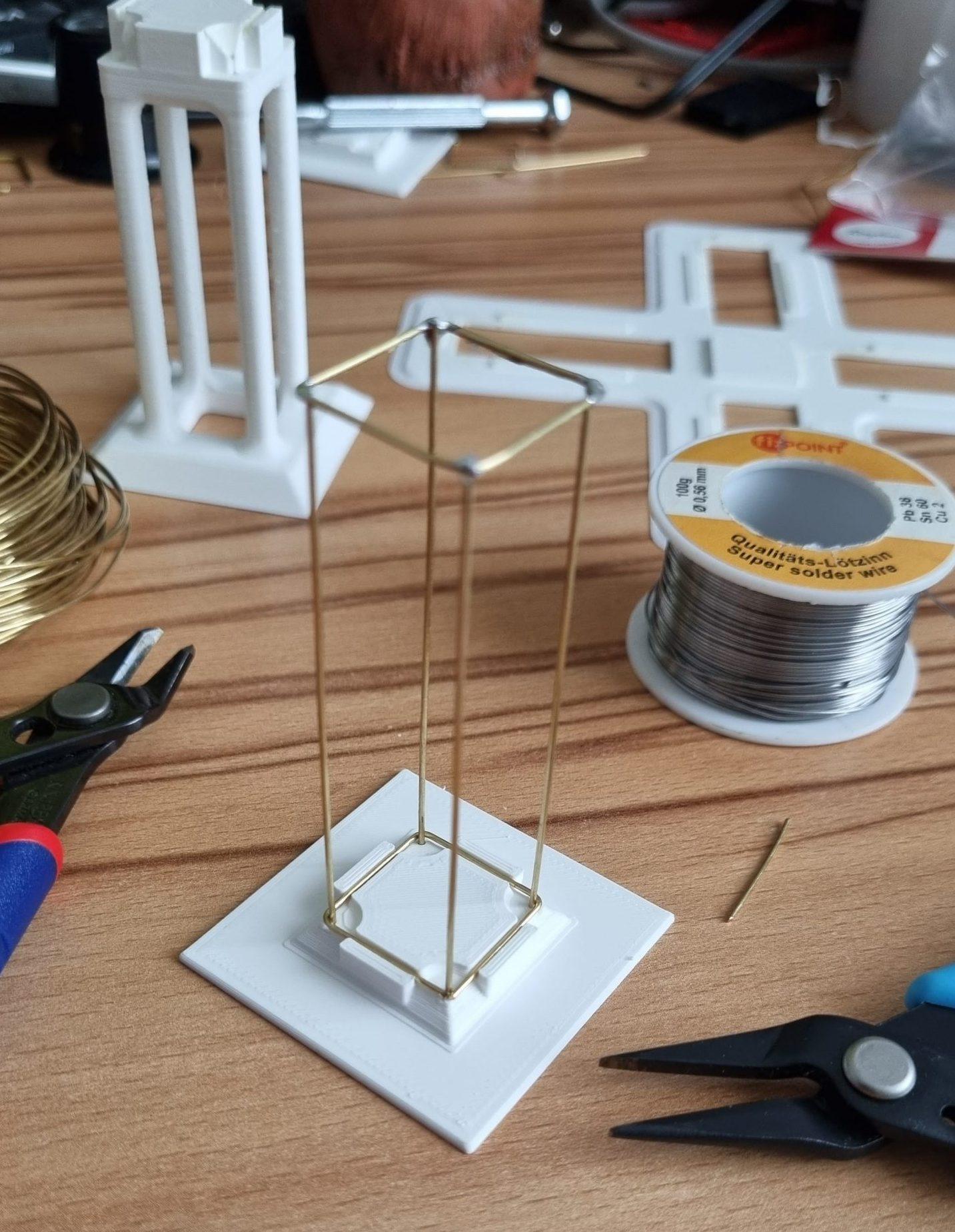
Square Jig

Used to create the three squares that belong to the main body structure. We can start with this form first followed by the four sides wit hthe help of the side jigs.
Side Jig


Used as a guide for the 4 sides that are going to hold the solar panels. The squared shape made in the previous step can be soldered to the first two sides withe the help of this jig.
Side Support Jig


Comes in handy when soldering the central square to the last two sides as support.
Panels Jig

.jpg)


This jig helps to get the frame in place with the right position so the solar cells can be soldered easily and on their correct position. We can always go back to the 1:1 pdf and check if the results are aligned with the reference ;)
Notice that small axial capacitors are used to provide strength to the structure without making a short between unwanted parts ;) The same concept is used when joining the two main body parts.
Body Jig 1


Once the panels are in place we can start with the satellite´s body. This jig provides the required support to solder the first part of the main body.
Body Jig 2


.jpg)
The last jig provides support for soldering the bottom side of the main body
Build the Guts!


Following the schematics proceed to put all the components together. This might be the most challenging part of this project! One very important part is to get the microcontroller flashed with the provided firmware before soldering it.
The same electronic used for the original sAttiny has been applied here. The only differences are the new solar cells and an additional 4uF gold cap connected in parallel to the previous one.
Github repo
All details related to the code running in the Attiny can be found in the link below:
Put All Together


Once we have all components and structures in place we can proceed to join the two main parts of the body.