GPS Location Display System
by devkrishnavhora in Circuits > Arduino
238 Views, 1 Favorites, 0 Comments
GPS Location Display System
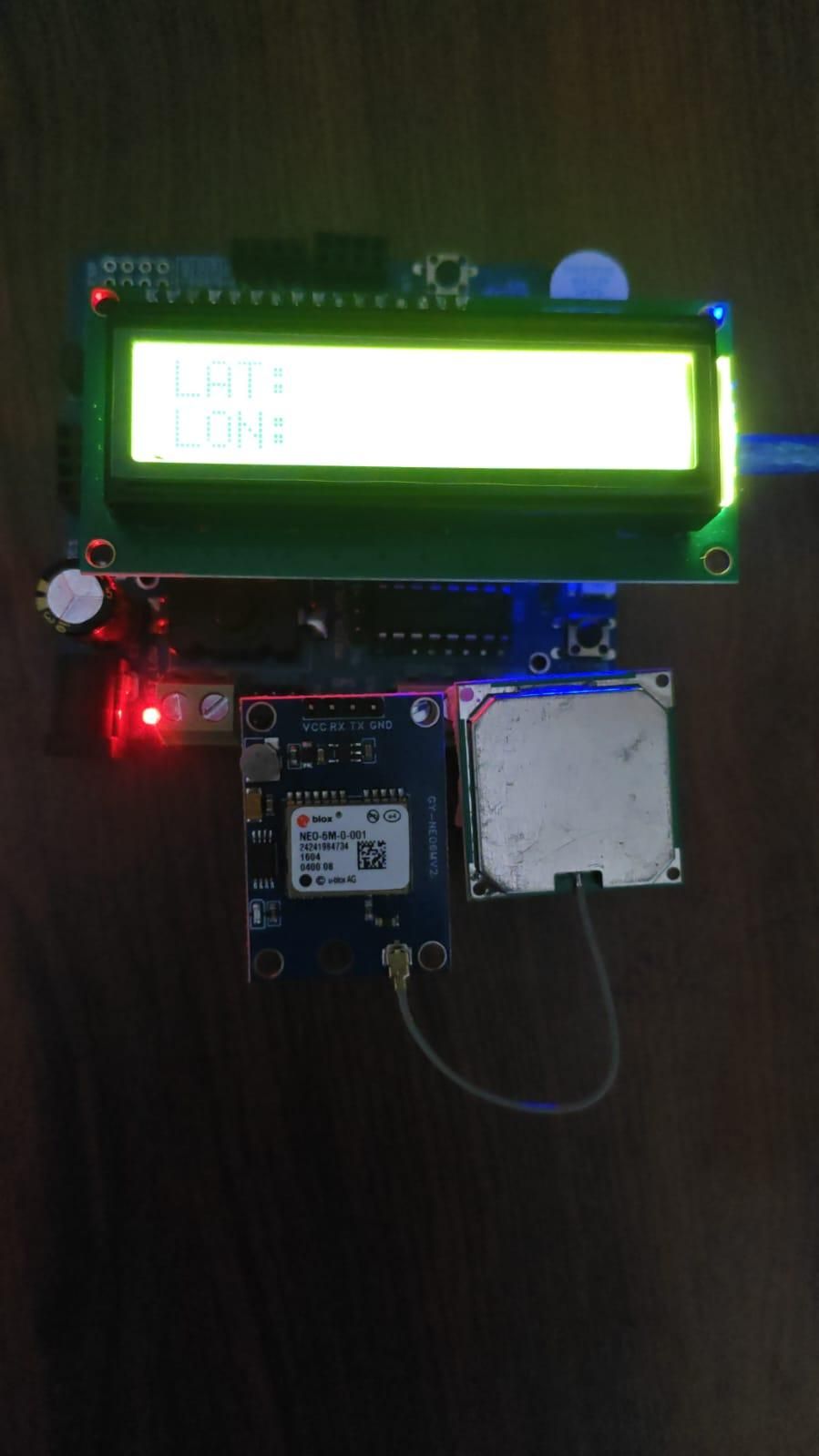
GPS Location Display System Using Arduino Nano and NEO-6M
Introduction
This project is a GPS-based location monitoring system built using an Arduino Nano, DESHBOT Shield, NEO-6M GPS module, and display modules. The main purpose of the project is to receive location information from GPS satellites and display the collected data in an easy-to-read format.
The Arduino Nano works as the main controller, while the DESHBOT Shield provides convenient connections for the Arduino and external modules. The NEO-6M GPS module receives satellite signals and sends location data to the Arduino. A 16×2 display is used to show information such as latitude and longitude, and a 7-segment display can be used to display selected numerical information.
This project can be used as a basic system for robot navigation, vehicle tracking, location monitoring, and GPS-based robotics projects.
Supplies
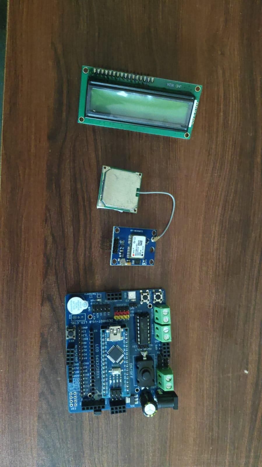
Components Required
- Arduino Nano
- DESHBOT Shield
- NEO-6M GPS Module
- 16×2 Display
- 7-Segment Display
- Jumper Wires
- USB Cable
- Power Supply
Prepare the DESHBOT Shield
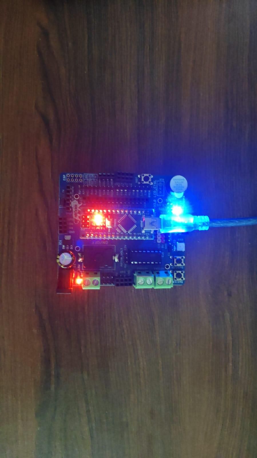
The DESHBOT Shield is the main connection board used in this project. It provides convenient connections for the Arduino Nano and external electronic modules.
Carefully inspect the labels printed on the shield before making any connections. Identify the power pins, ground pins, analog pins, digital pins, and communication connections.
Make sure that the power supply is disconnected while assembling the circuit. This helps prevent accidental short circuits or damage to the electronic components.
Insert the Arduino Nano Into the Shield
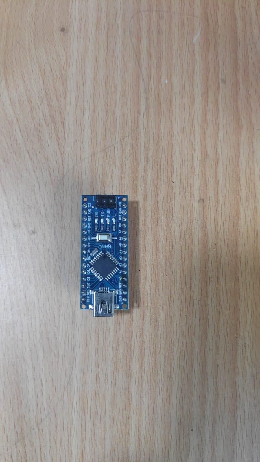
Carefully insert the Arduino Nano into the correct socket on the DESHBOT Shield. Make sure all the pins are properly aligned before applying pressure.
Do not force the Arduino into the socket because bent pins can cause connection problems. Once inserted correctly, check that the Arduino Nano is firmly connected to the shield.
The Arduino Nano will act as the main controller of the project. It will receive information from the NEO-6M GPS module, process the GPS data, and control the 16×2 display and 7-segment display.
Mount the NEO-6M GPS Module
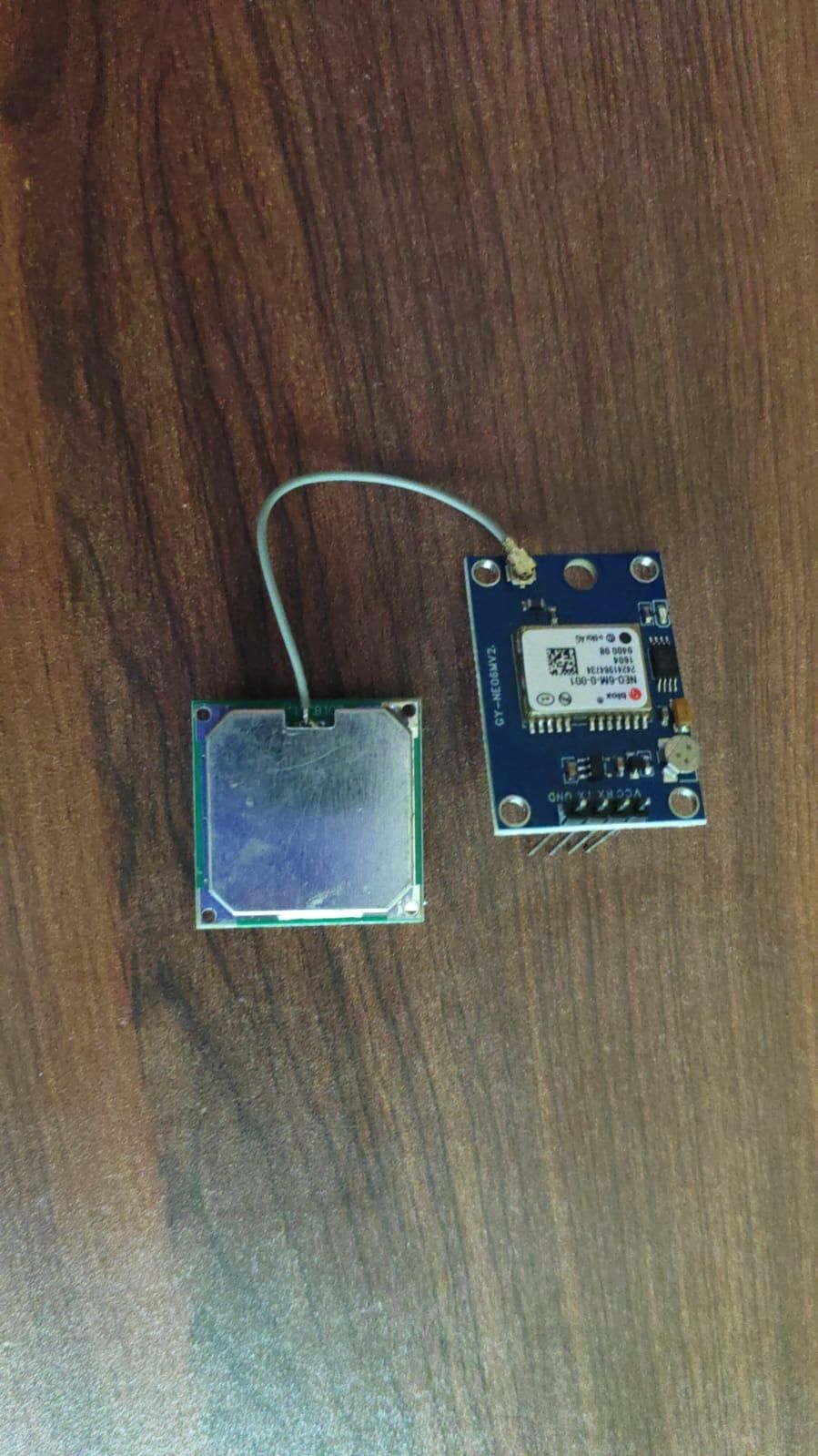
Place the NEO-6M GPS module in a suitable position near the Arduino system. The GPS antenna should be positioned so that it can receive signals from satellites.
The GPS module works best when it has a clear view of the sky. Avoid placing the antenna under large metal objects or inside a completely enclosed metal box, as this can reduce the quality of the GPS signal.
Secure the GPS module and its antenna so that the connections do not become loose while testing the project.
Connect the NEO-6M GPS Module
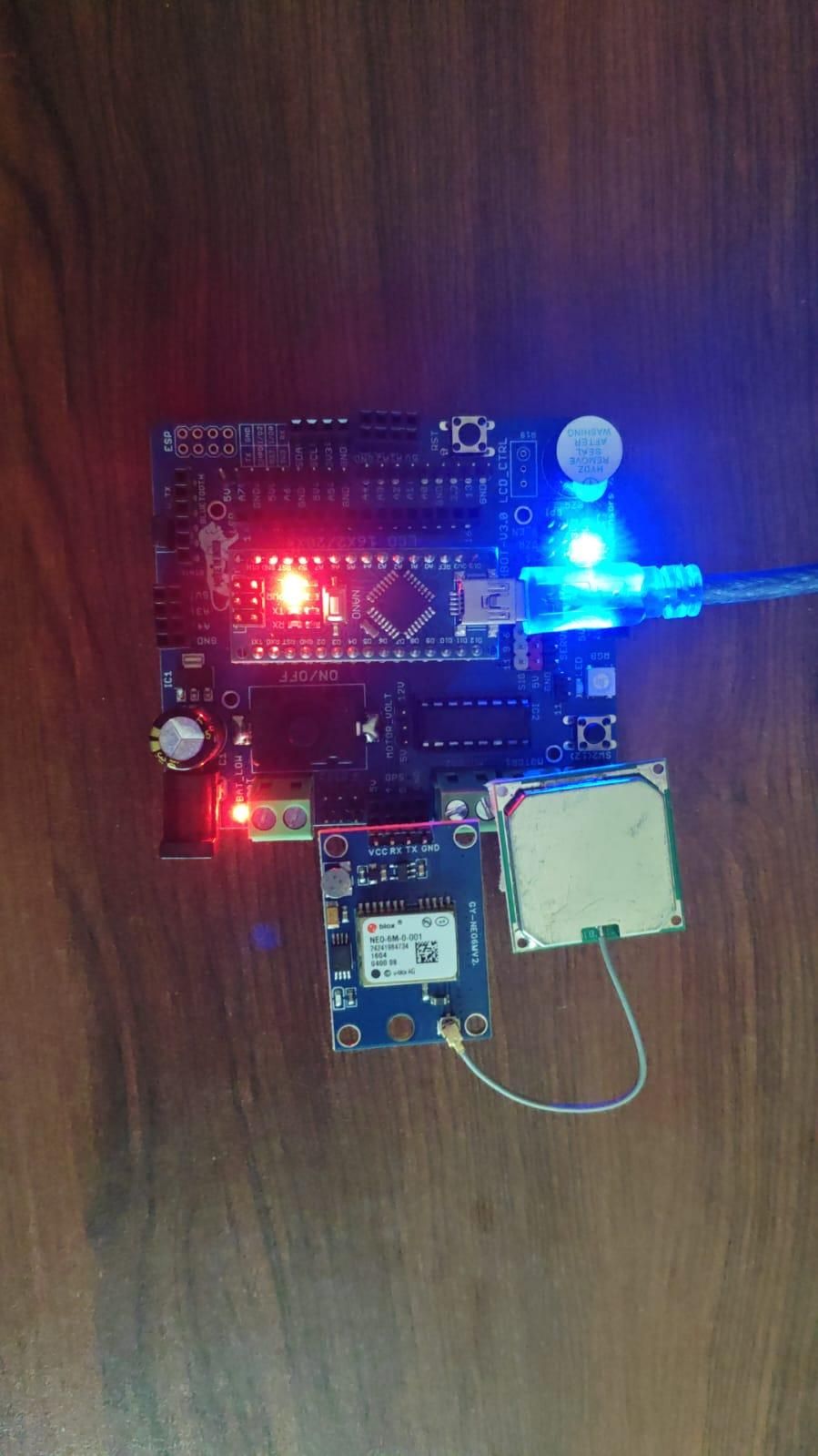
Connect the NEO-6M GPS module to the Arduino Nano through the DESHBOT Shield.
The GPS module normally has the following main connections:
- VCC – Power supply
- GND – Ground
- TX – Serial data output
- RX – Serial data input
Connect the VCC and GND pins to the appropriate power connections on the shield. Connect the communication pins according to the Arduino program.
The TX pin of the GPS module sends GPS data to the Arduino. The Arduino reads this serial data and extracts useful information such as latitude, longitude, satellite information, and GPS status.
Always check the TX and RX wiring carefully. Incorrect serial connections can prevent the Arduino from receiving GPS data.
Connect the 16×2 Display
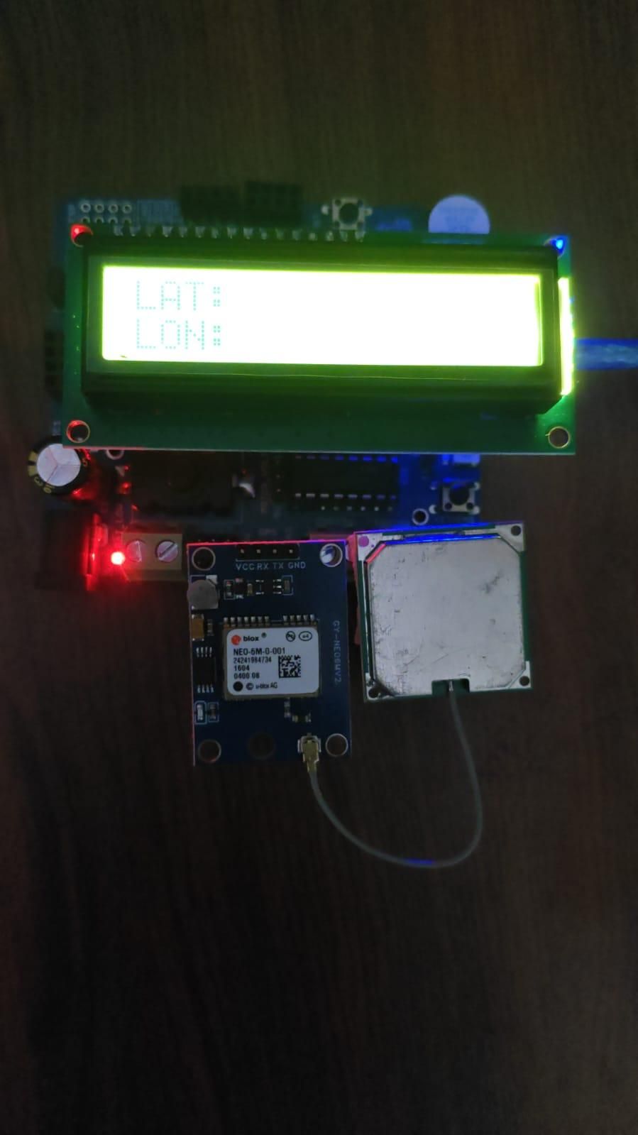
Next, connect the 16×2 display to the Arduino Nano through the DESHBOT Shield.
The 16×2 display is used to show GPS information in a readable text format. Depending on the program, it can display the GPS connection status, latitude, longitude, number of satellites, or other useful information.
Make sure that the display receives the correct operating voltage and that the communication wires are connected to the correct pins.
After connecting the display, check that all jumper wires are firmly attached. Loose wires can cause the display to show incorrect characters or remain blank.
: Check All the Wiring
Before connecting the power supply, carefully inspect the complete circuit.
Check the following points:
- Arduino Nano is properly inserted into the DESHBOT Shield.
- NEO-6M GPS module is connected correctly.
- GPS VCC and GND connections are correct.
- GPS TX and RX connections match the Arduino program.
- 16×2 display is connected properly.
- 7-segment display is connected properly.
- All ground connections are secure.
- No jumper wires are loose or touching incorrectly.
This step is very important because incorrect wiring can cause communication problems or damage electronic components.
Connect the Arduino Nano to the Computer
Connect the Arduino Nano to a computer using a USB cable.
Open the Arduino IDE and select the correct Arduino board and communication port. Make sure the computer successfully detects the Arduino Nano before uploading the program.
If the Arduino Nano is not detected, check the USB cable, USB port, board selection, and required drivers.
Once the connection is successful, the Arduino is ready for programming
Upload the GPS Program
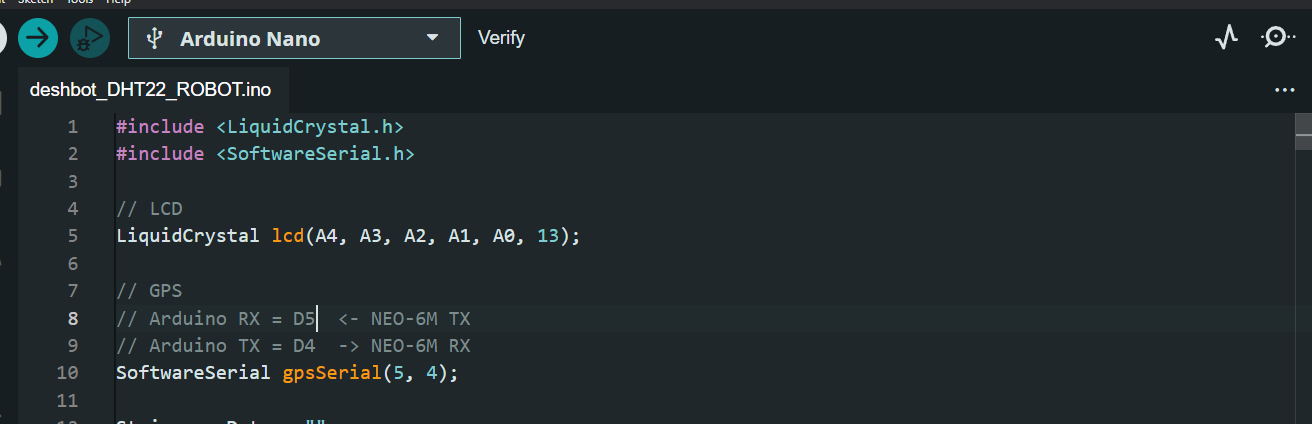
Write or upload the Arduino program for the project.
The program should perform the following main tasks:
- Initialize communication with the GPS module.
- Read serial data received from the NEO-6M.
- Process the GPS information.
- Check whether a valid GPS location is available.
- Send the required information to the 16×2 display.
- Send selected numerical information to the 7-segment display.
- Continuously update the displays.
Before uploading, make sure the pin numbers in the program match the actual wiring of the project.
After checking the code, upload it to the Arduino Nano.
: Power on the System
After successfully uploading the program, power the Arduino system.
The displays should initialize when the system starts. The NEO-6M GPS module will also begin searching for satellite signals.
During startup, the program can display a message such as “GPS Searching” or “Waiting for Signal” until valid GPS information is received.
The time required to obtain a GPS signal can vary depending on the location, weather, antenna position, and satellite visibility.
Move the GPS Antenna to an Open Area
For proper testing, move the GPS antenna to an outdoor location with a clear view of the sky.
The NEO-6M module may have difficulty receiving enough satellite signals inside buildings. Walls, roofs, and nearby structures can reduce signal strength.
Wait for the GPS module to establish a satellite connection. The module's indicator LED may provide information about its connection status, depending on the version of the module.
Once the module receives a valid GPS fix, location information can be sent to the Arduino Nano.
: Check the 7-Segment Display
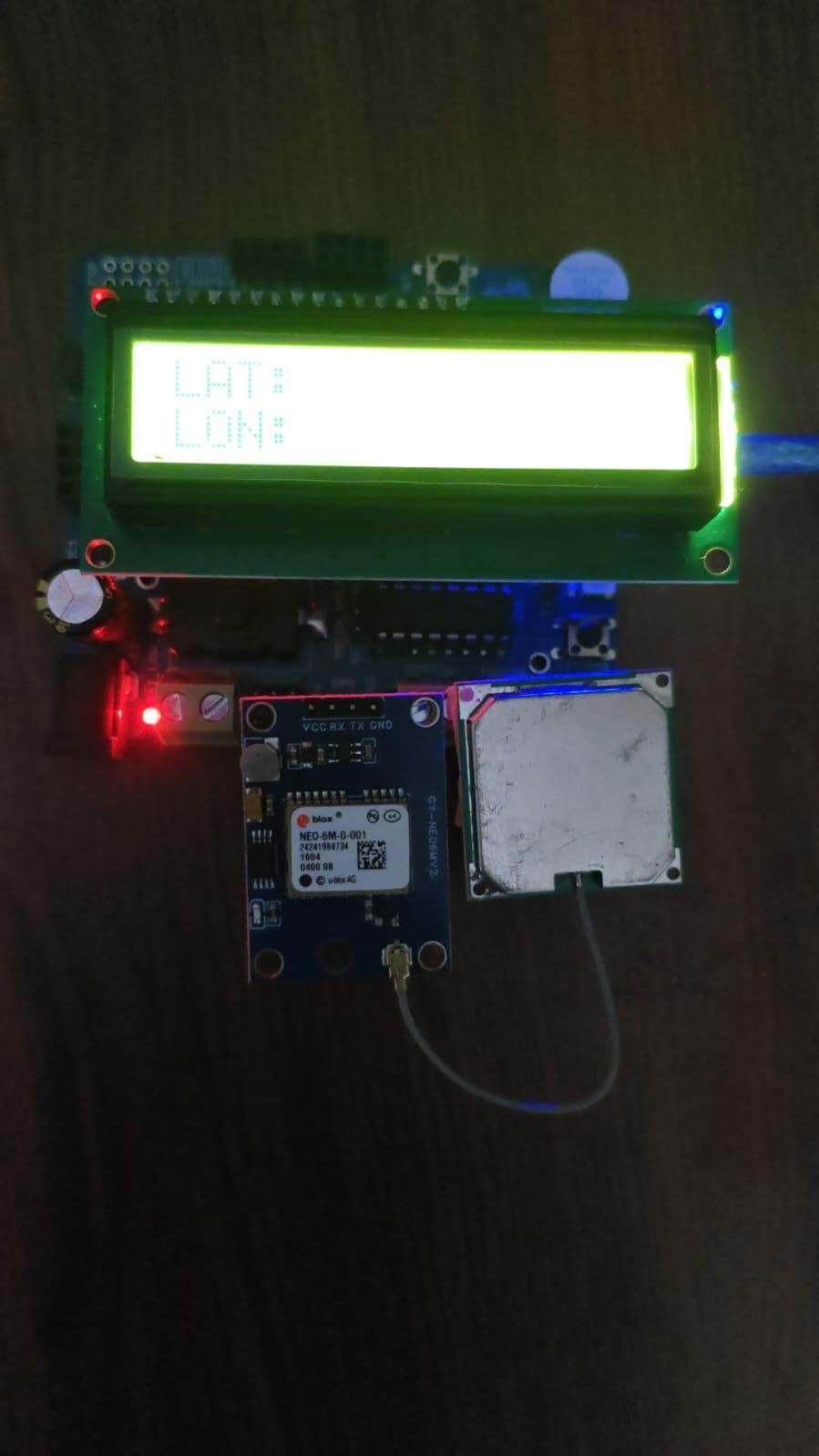
Observe the 7-segment display after the system starts.
The display should show the numerical information selected in the Arduino program. The value can change as new information is received and processed.
If the display does not work correctly, check the following:
- Display power connection
- Ground connection
- Data pins
- Arduino pin configuration
- Program code
Correct any wiring problems and test the system again.
Test the Complete System
After all modules are working correctly, test the complete project together.
Allow the GPS module to receive satellite data. Check whether the Arduino Nano is successfully receiving information from the NEO-6M GPS module.
Verify that the 16×2 display shows the correct programmed information and that the 7-segment display updates correctly.
Move the GPS antenna to a different location if required and observe whether the GPS values change. This confirms that the system is receiving and processing live location information.
Final Working
After completing all the steps, the project works as a GPS-based monitoring and display system. The NEO-6M GPS module receives location information from GPS satellites and sends the data to the Arduino Nano.
The Arduino Nano processes the received information and controls the connected displays through the DESHBOT Shield. The 16×2 display shows detailed GPS information, while the 7-segment display provides a simple numerical output.
This project can be expanded in the future by adding features such as robot navigation, GPS tracking, data logging, Bluetooth communication, GSM communication, IoT connectivity, or automatic waypoint navigation.