Gameboy With ESP32-S3 NANO.
by Nochii in Circuits > Electronics
3449 Views, 33 Favorites, 0 Comments
Gameboy With ESP32-S3 NANO.
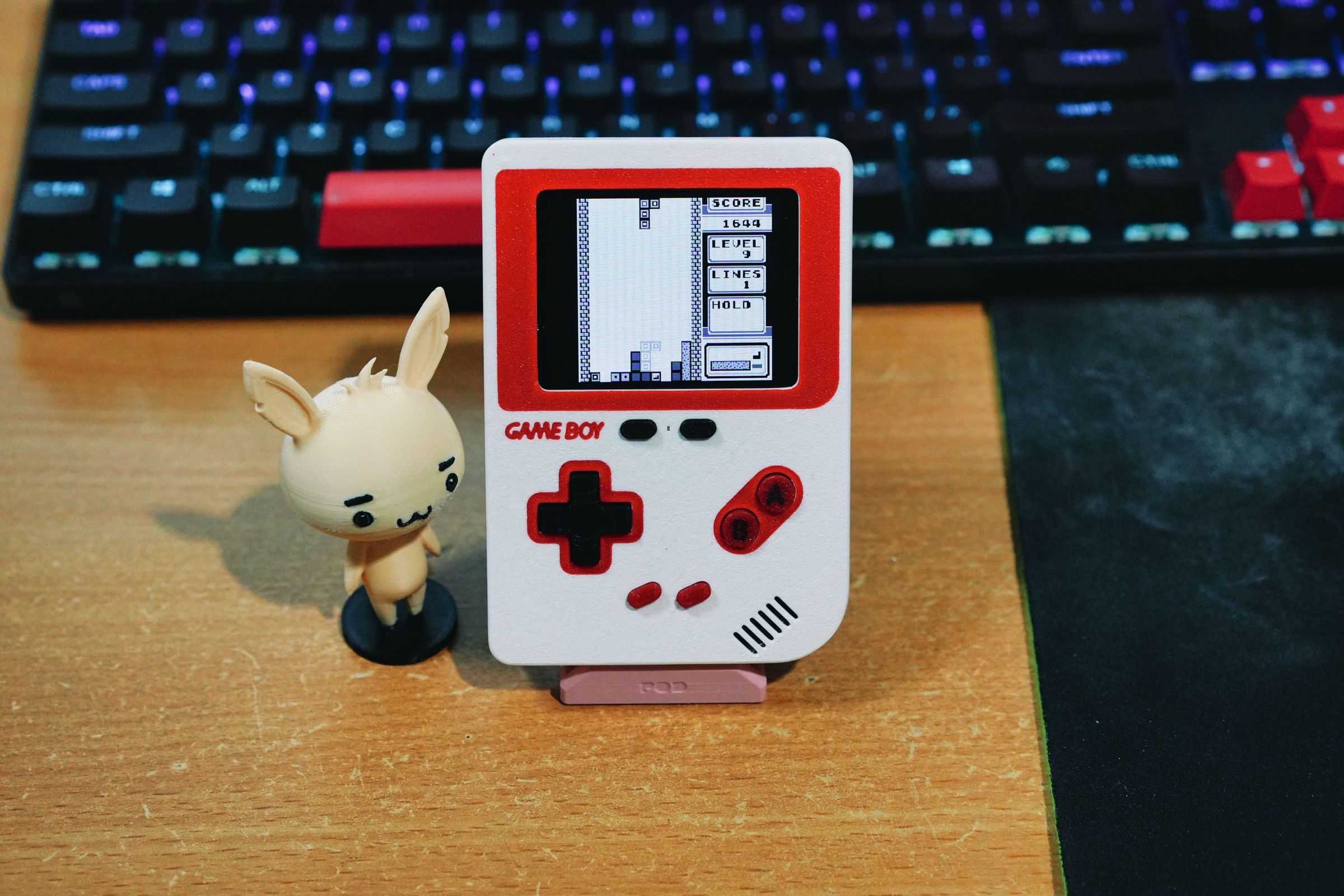
I previously tried making a Retro-go console using the ESP32-S3 Nano, but when I let several people around my age try it out, they all said the same thing: 'It's too small.' After getting that feedback, I decided to make a slightly larger version that is still easy to carry around and comfortable to play. At first, I created an SNES version, which played pretty well, but I felt the wiring was a bit too complicated and there were still a few user-experience pain points. So, I redesigned it into this version that anyone can easily build. This is also my very first time writing a tutorial here on Instructables.
If you're interested in the previous version, you can check it out here.
Supplies
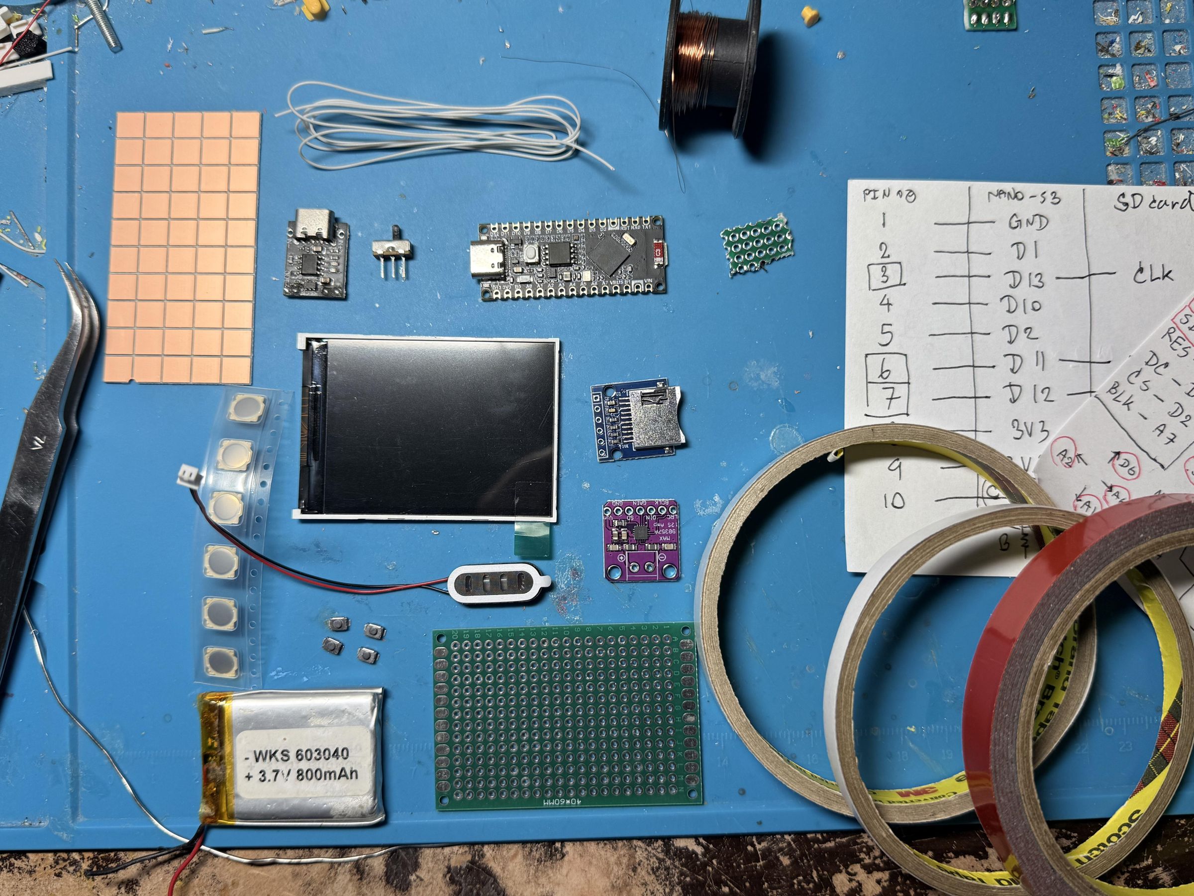
- Waveshare ESP32-S3-Nano
- 2.4 Inch TFT Display Modules ST7789V Drive 10PIN
- FPC FFC Flexible Flat Cable Welded Board Adapter PCB Board 0.5mm Pitch Connector SMT To 2.54mm Hole 10PIN
- 0.5MM Flat Flexible Cable FFC/FPC 10PIN
- Mini Micro SD TF Card Storage Expansion Board
- MAX98357 I2S 3W Class D Amplifier
- Small Double-Sided Copper Plate
- 40x60mm Double Side Prototype Diy Universal Printed Circuit PCB Board Protoboard
- ALPS SKRRABE010 Thin Film Tactile Switch 7.5*7*0.6 SMD 4-pin (or any switch I show in tutorial that you can provide)
- Copper Soldering Wire PCB Link Jumper Wire Computer Motherboard Welding Repair Tools
- Double-sided adhesive tape
- LiPo battery no larger than 50 mm × 70 mm and no thicker than 55 mm
- Any NPN transistor will work, but the example recommends a 2N2222 or BC547B. (2N2222 is good option)
- If using the recommended transistor, use a 10 Ω resistor. If using a 2N2222, use a 1 kΩ resistor.
- Resistor 100kΩ x2, 10kΩ x1
- Capacitor 0.1uF x1
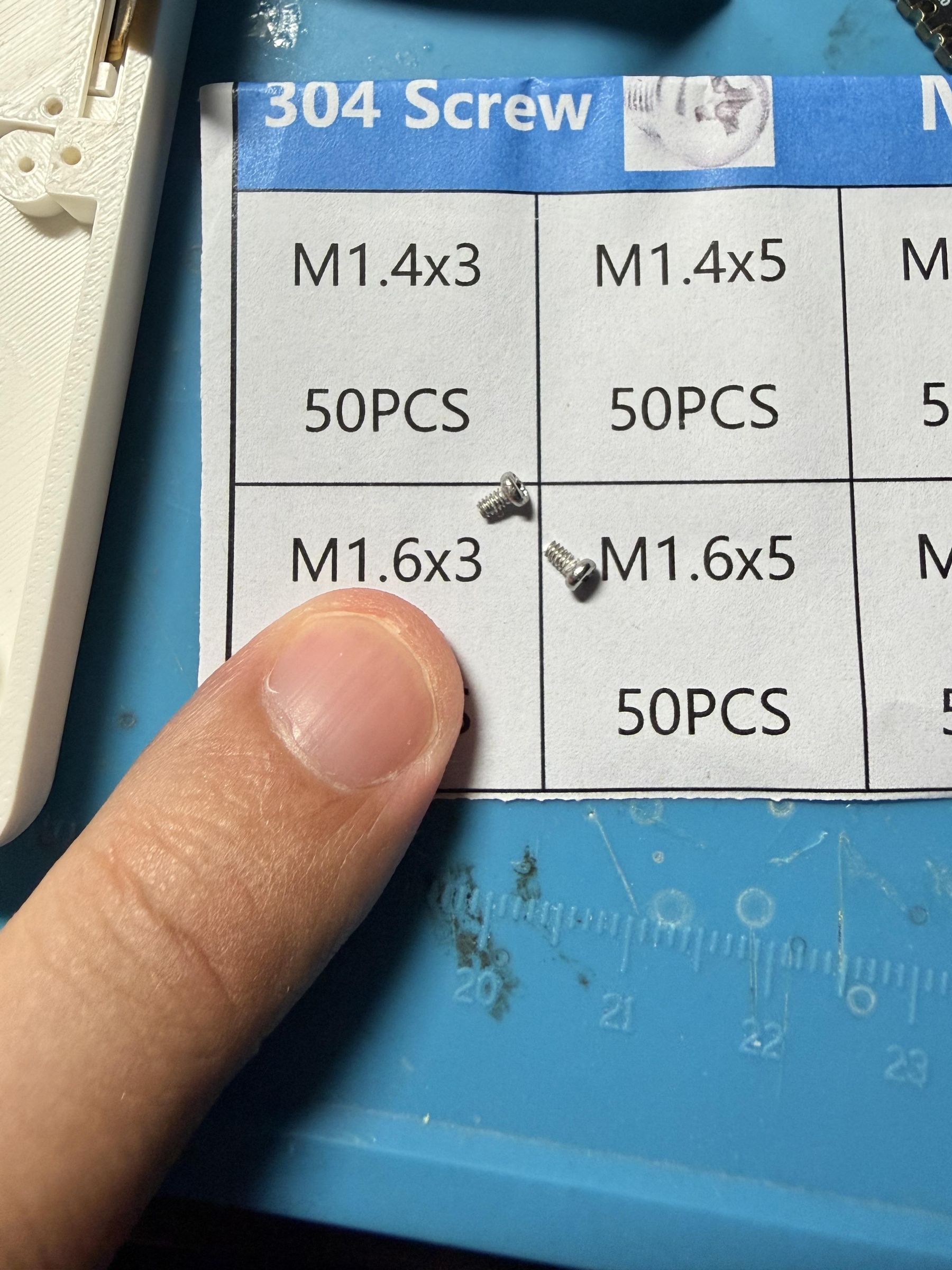
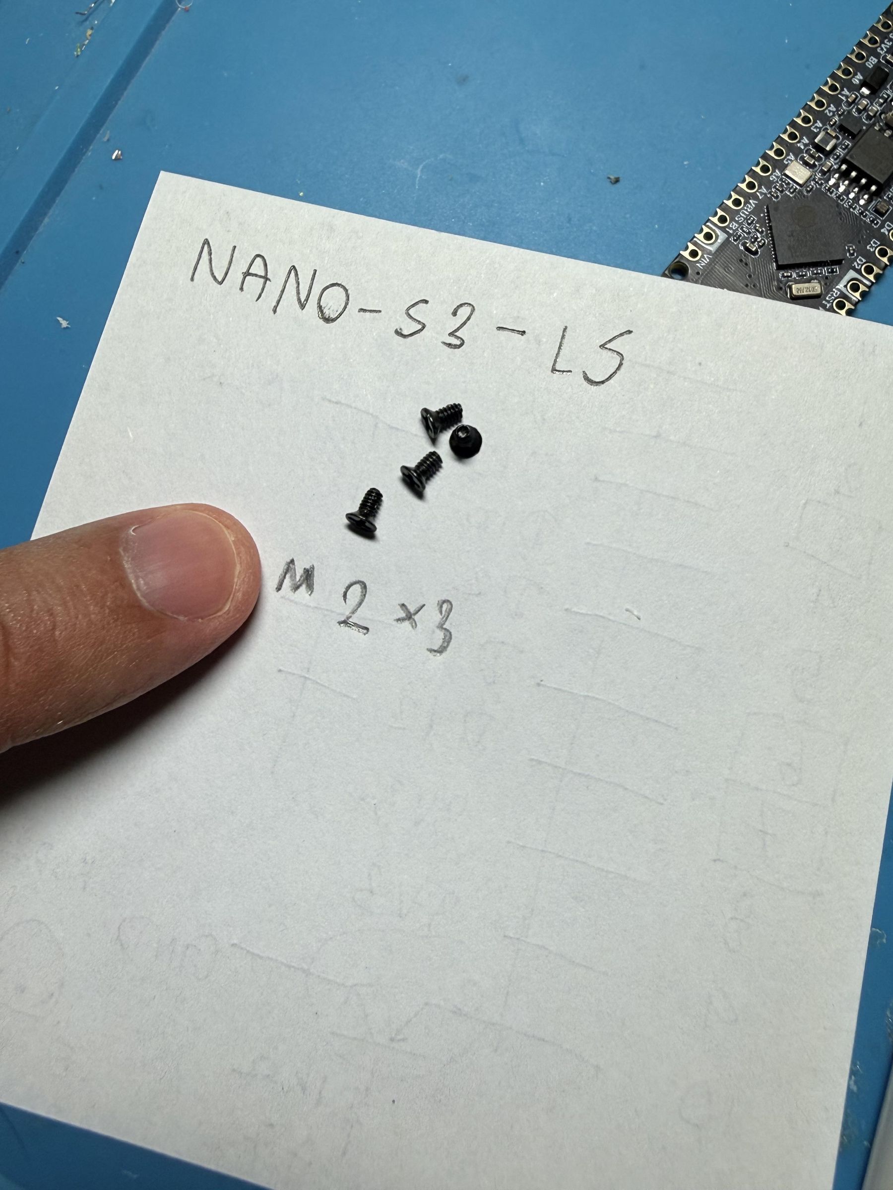
- Screws: 6 × [M1.6×3], 4 × [M2×3], and 6 × [M1.6×8].
- Small 8 Ω speaker, 29 × 9 × 4 mm.
Print All the 3D Parts and Check the Equipment Before Starting.
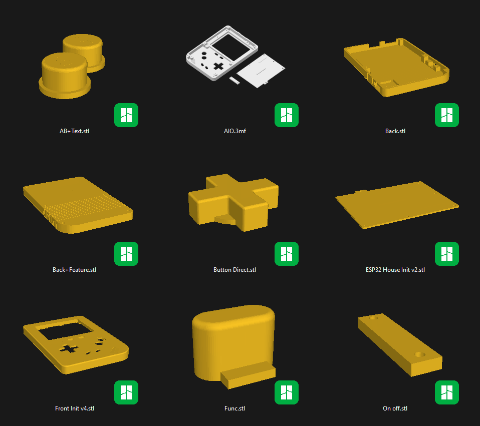
Prepare all of the components listed above and 3D-print the required parts. If you use Bambu Lab Slicer, you can print them directly from the AIO file.
(or load .zip file here)
https://drive.google.com/file/d/1EGTf1Zb35-VmQmvTk9TxD2AQW_3zjx64/view?usp=sharing
Make sure you have enough double-sided tape and wire, and prepare your soldering equipment and multimeter. The tricky part is that you may need to cut pieces of PCB to assemble the SMD components. You can use standard through-hole components instead, but the result may not look as neat and you may need electrical tape to prevent short circuits
Install the Display and Prepare Space for the Module.
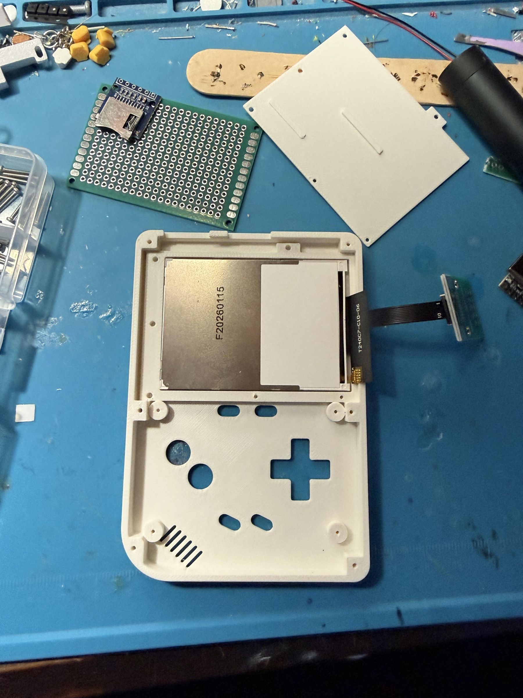
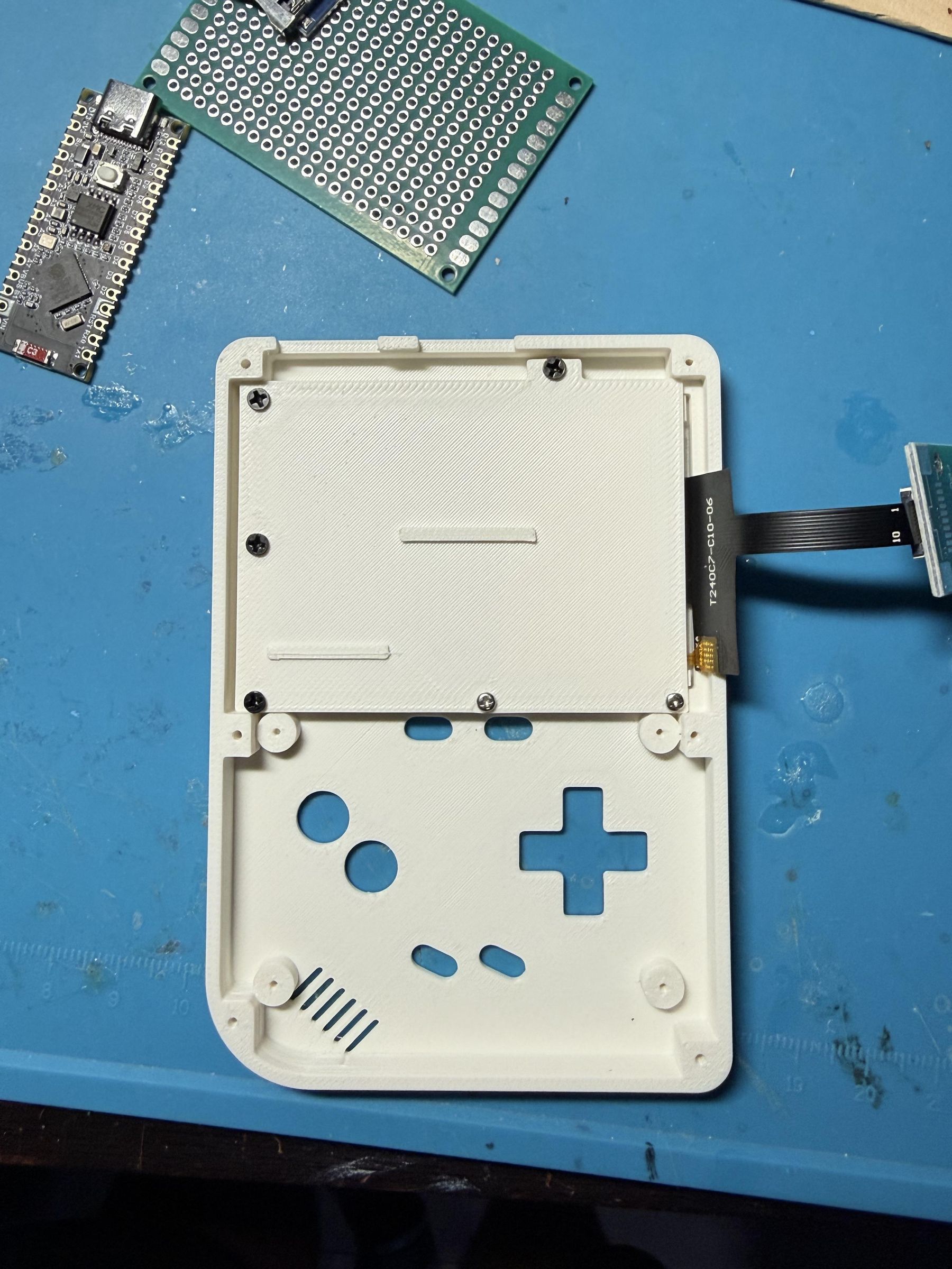
Connect the 2.4" display to the 10-pin connector and place it in the frame as shown. If it still moves, add small plastic pieces to keep the display in place, or use thin double-sided tape to secure it. (However, this may make adjustments more difficult if you need to remove it again later, so keep this in mind.)
Then attach the retaining cover as shown, using M1.6×3 and M2×3 screws. (I originally designed it to use all M2 screws, but after printing, the screw holes protruded and could weaken the rear mounting points. I changed them to M1.6 so they fit fully inside the holes.)
Install the Module to Test the Display.
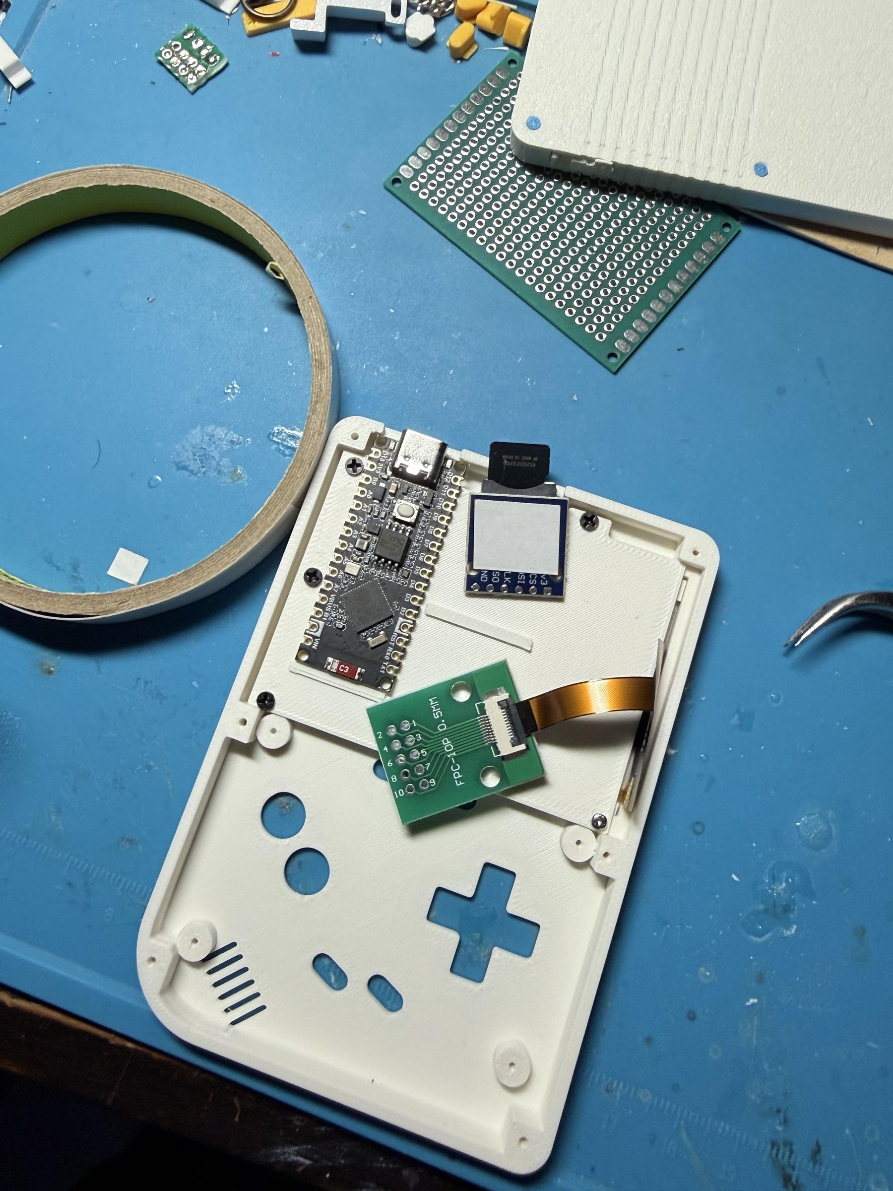
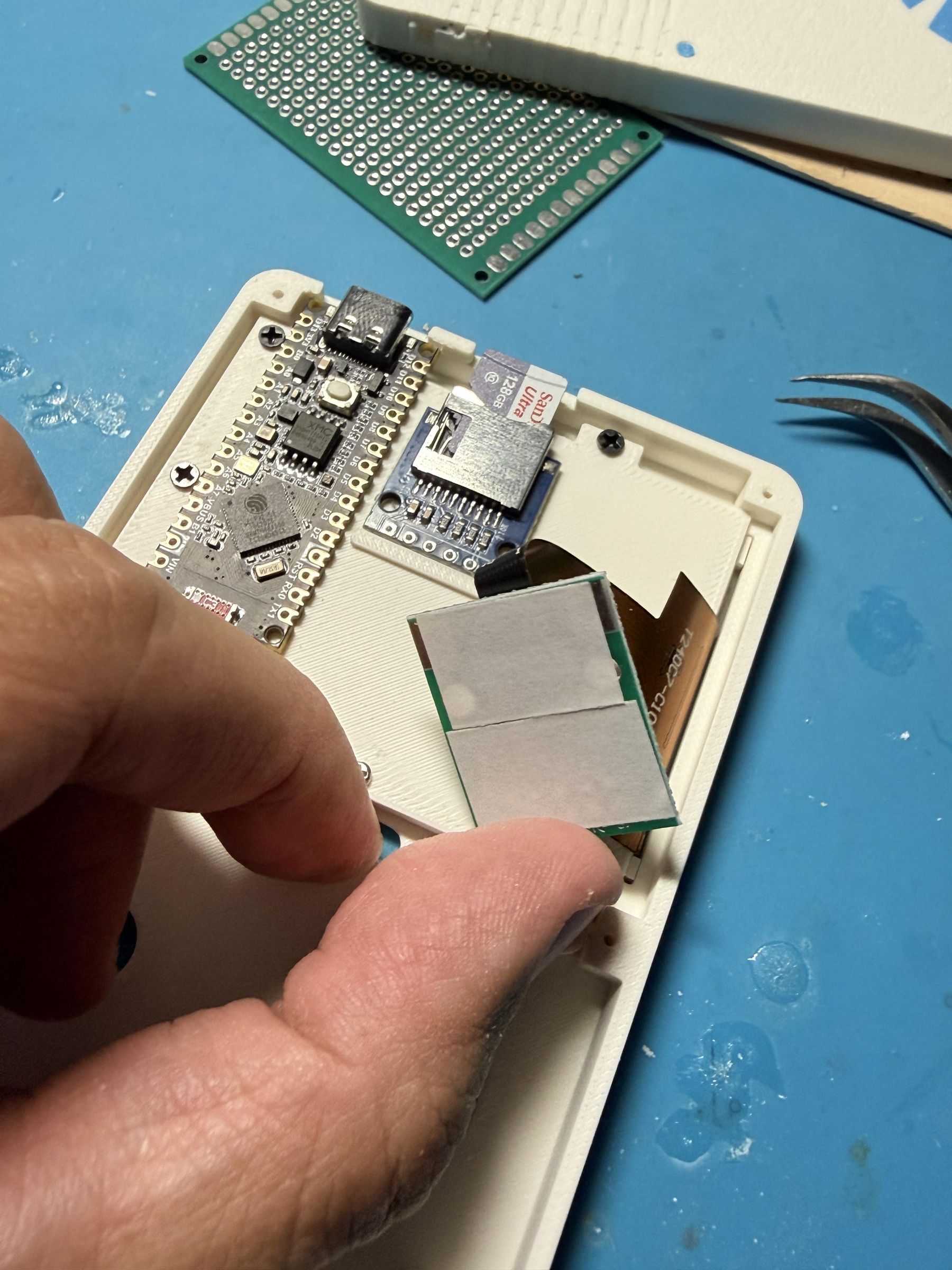
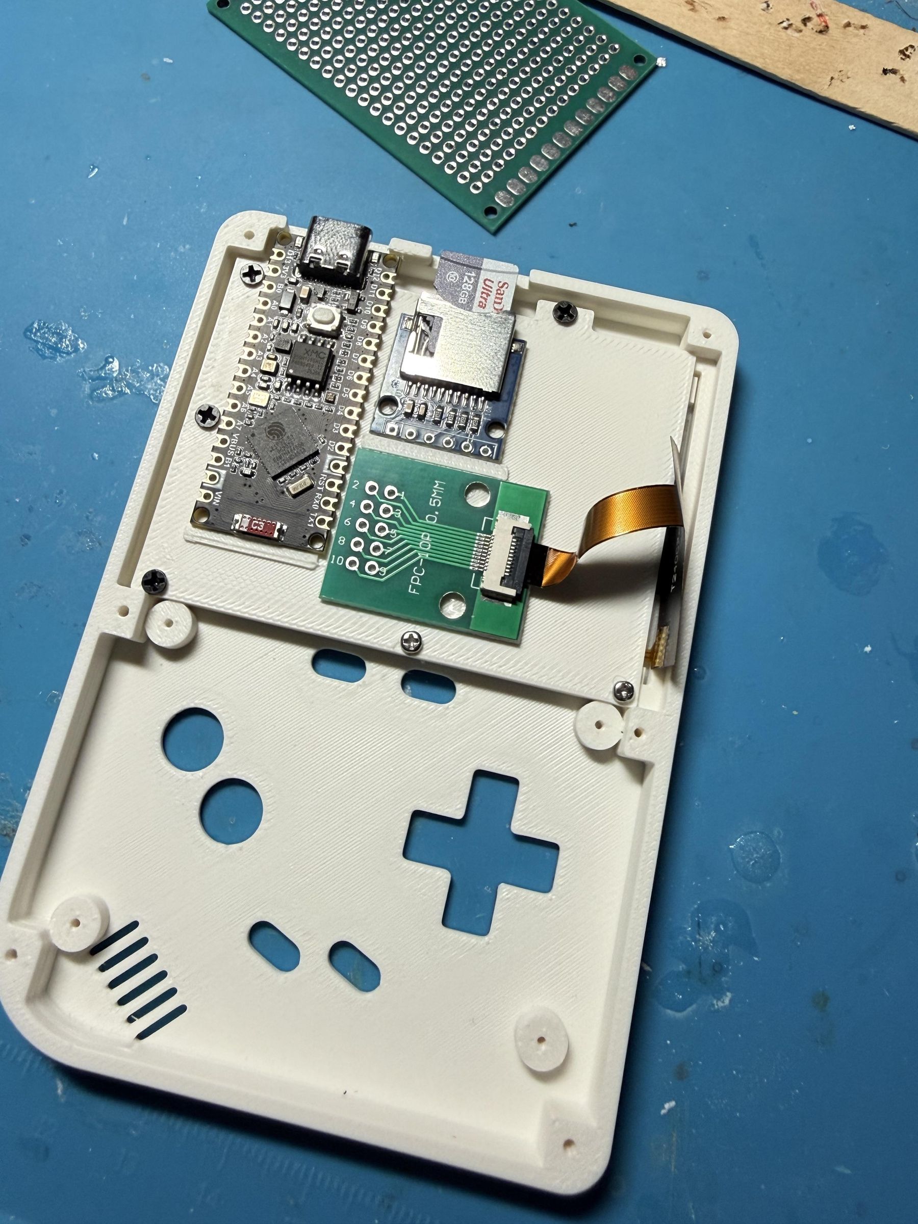
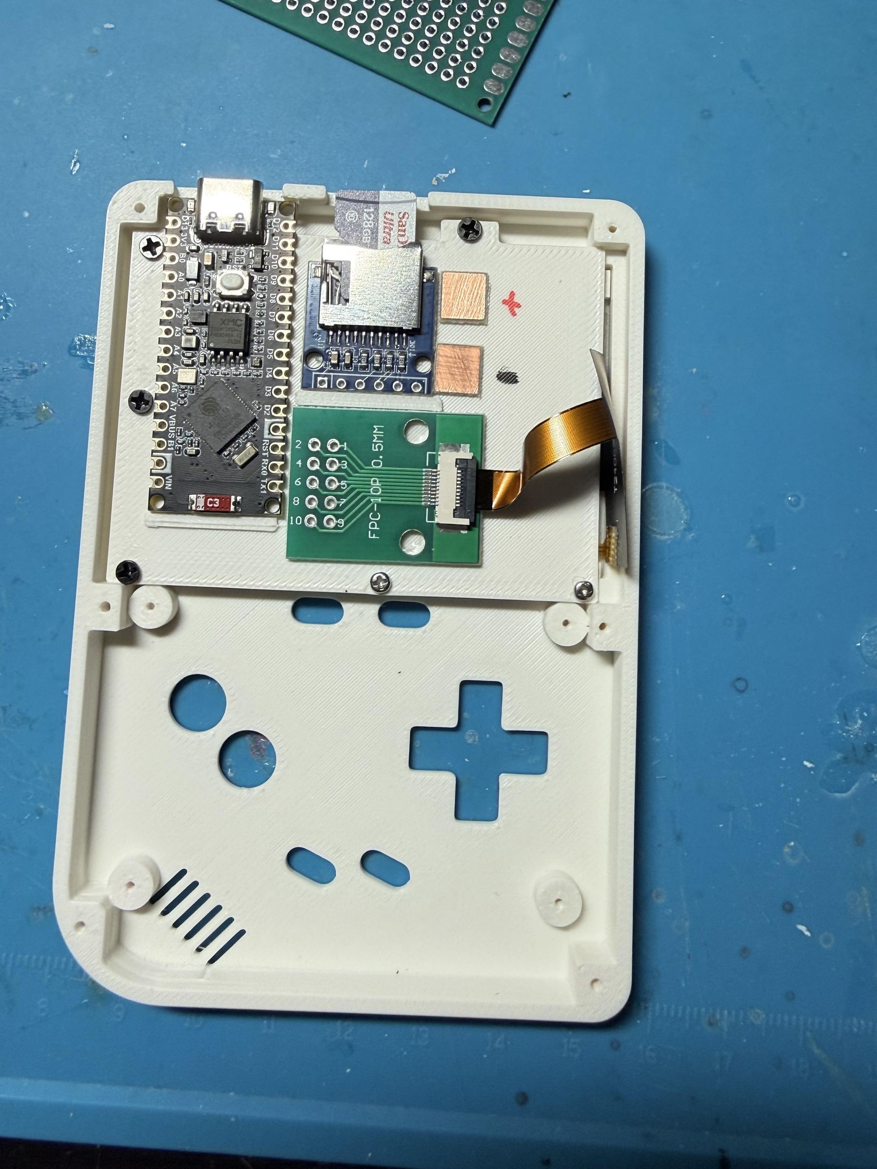
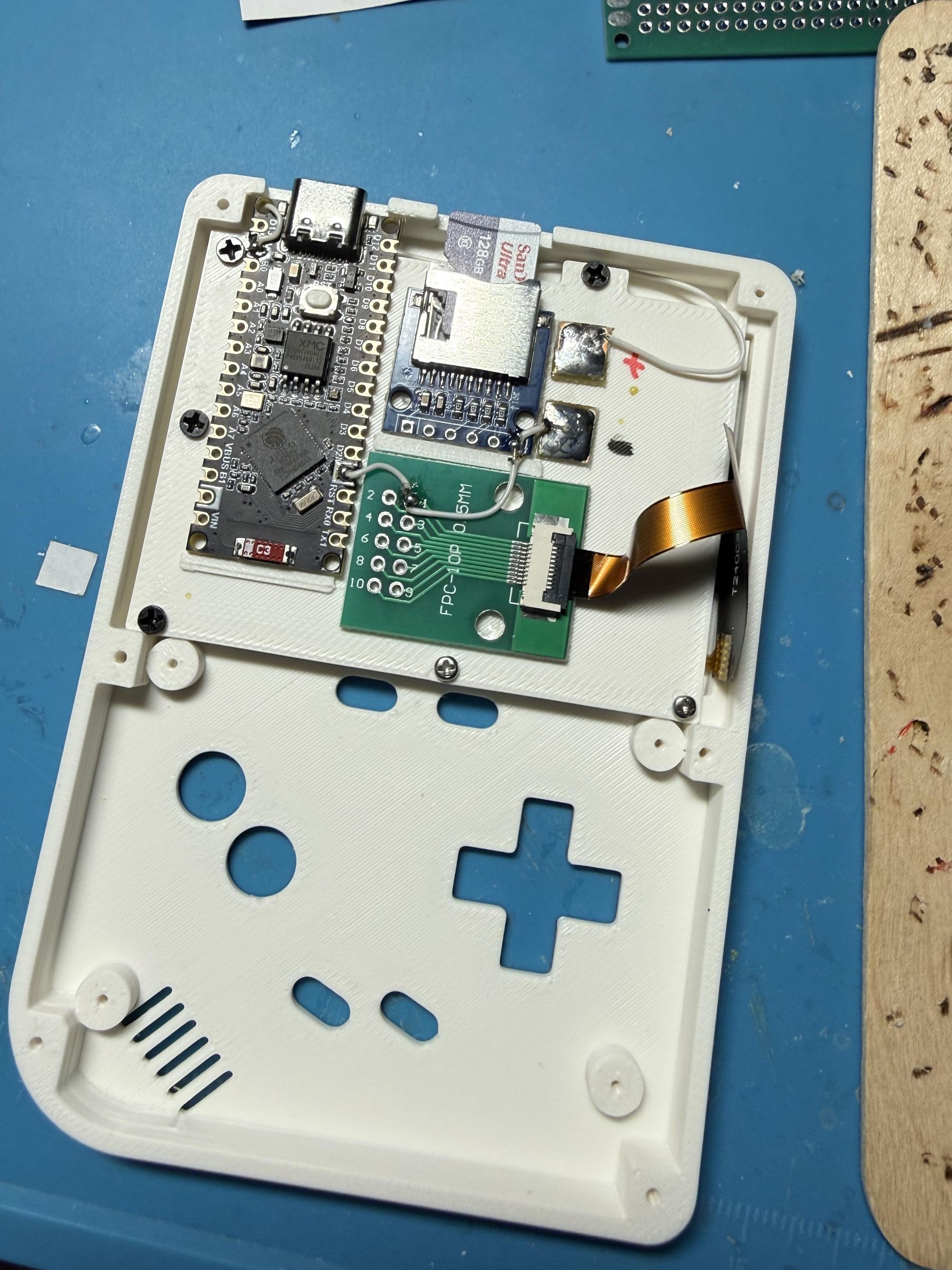
Before starting, flash the NANO-S3 so you can test it after installing the display. If you are unfamiliar with flashing, skip ahead to the Software section below, where I explain the process.
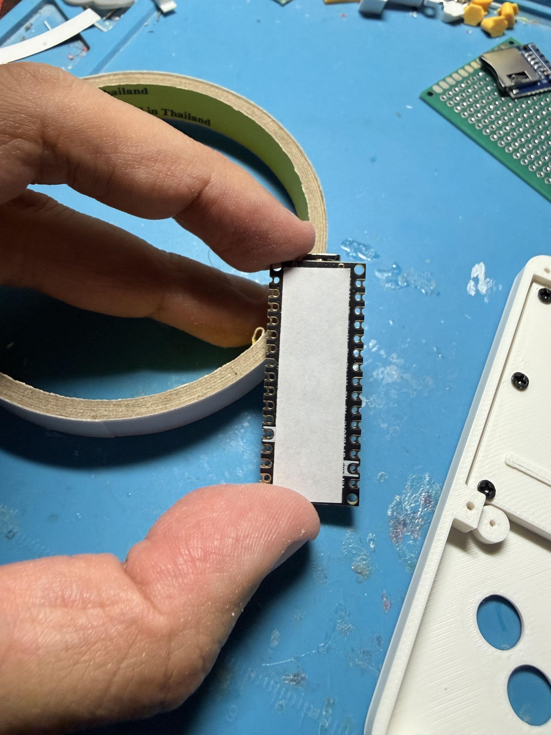
Apply double-sided tape to the Nano-S3, SD-card module, and FPC connector, then place them as shown.
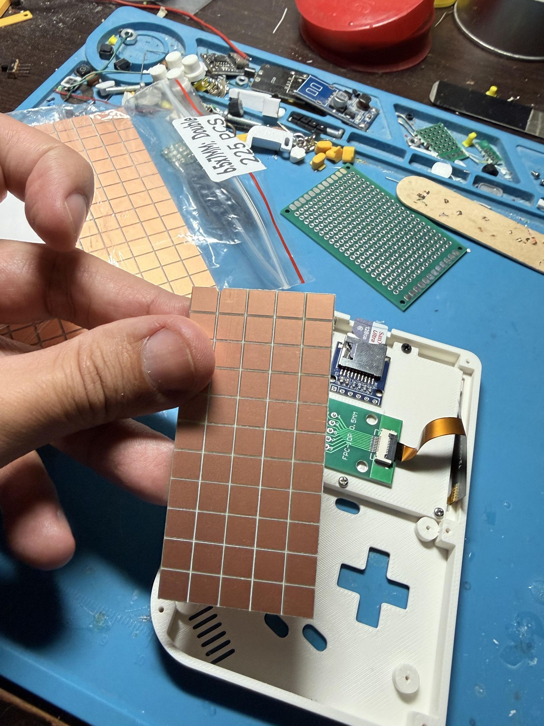
To make soldering the other parts easier, I used small copper pads as shown to create a common ground and a shared 3.3 V power rail. Since these points connect to several other modules, this small piece makes the soldering work easier.
Next, route the shared ground and 3.3 V wires first. Position them carefully and secure them with a small amount of adhesive so they do not move. Otherwise, when soldering the other shared wires, they may come loose from the copper pads. Securing them well with double-sided tape greatly reduces—or eliminates—the chance of detachment, making it easier to distribute the 3.3 V power and ground connections.
Solder the Transistor Section.
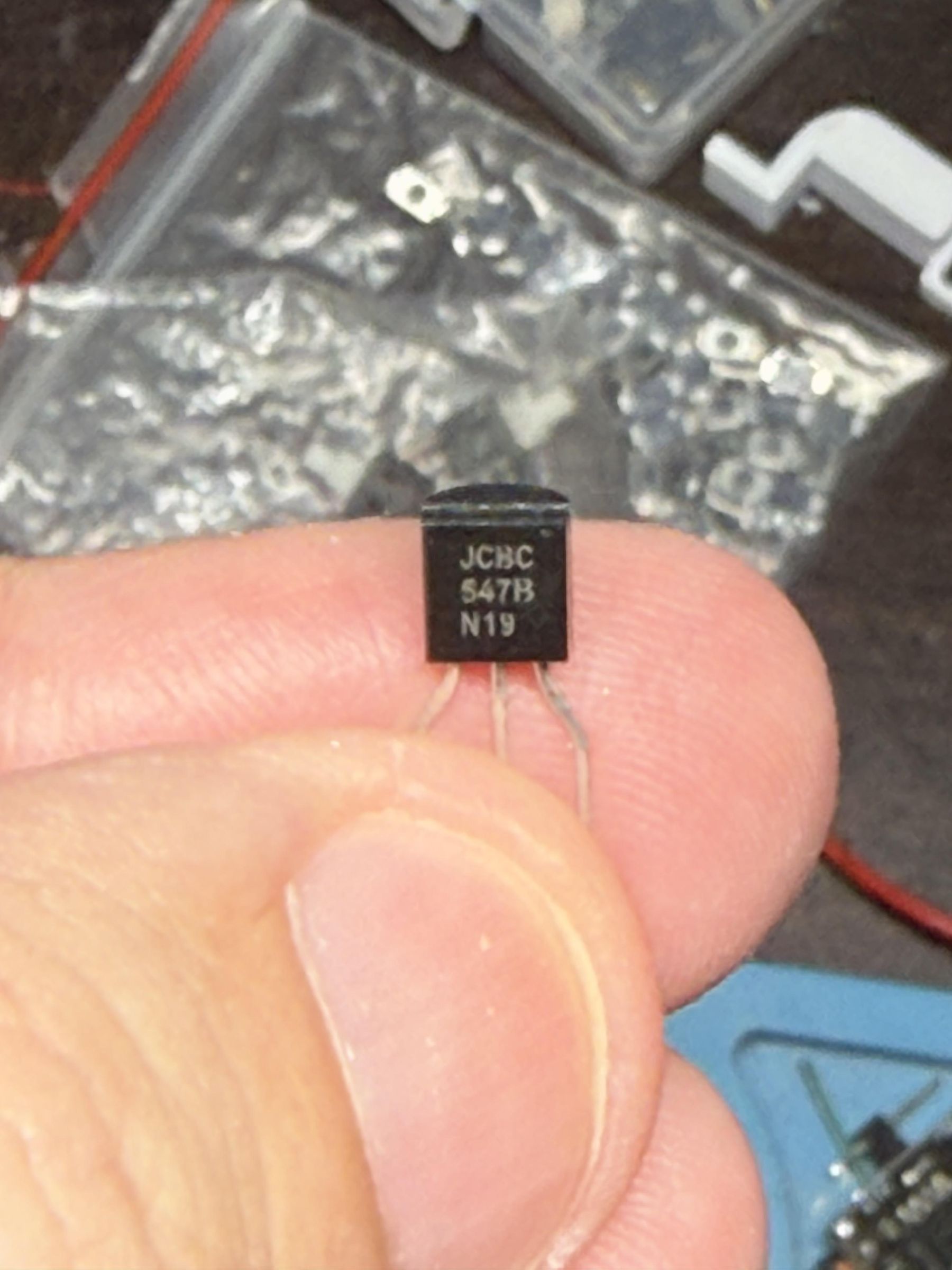
I separated this into a separate step because it has some details. If you use a 2N2222* NPN transistor, use a 1 kΩ resistor; if you use a BC547, you can use a resistor from 2.2Ω to 1 kΩ instead.Check your display module’s specifications to see whether it needs a capacitor across VCC and GND to filter electrical noise. The display I used did not require one because its current draw was low.
For the wiring, first check the transistor pinout. Connect the collector (C) to pin 10 of the display connector (which I will call the display from now on), and connect the emitter (E) to GND. Connect the base (B) through a 2.2 Ω, 10 Ω, or 1 kΩ resistor—depending on the transistor used—to the Nano-S3’s A7 port. In this tutorial, I will use the pin names printed on the Nano-S3 board instead of GPIO numbers to make them easier to identify before soldering.
* I strongly suggest 2N2222 with 1 kΩ resistor. BC647 is fine but not work as well as 2N2222.
Connect All Display and SDCard Wires.
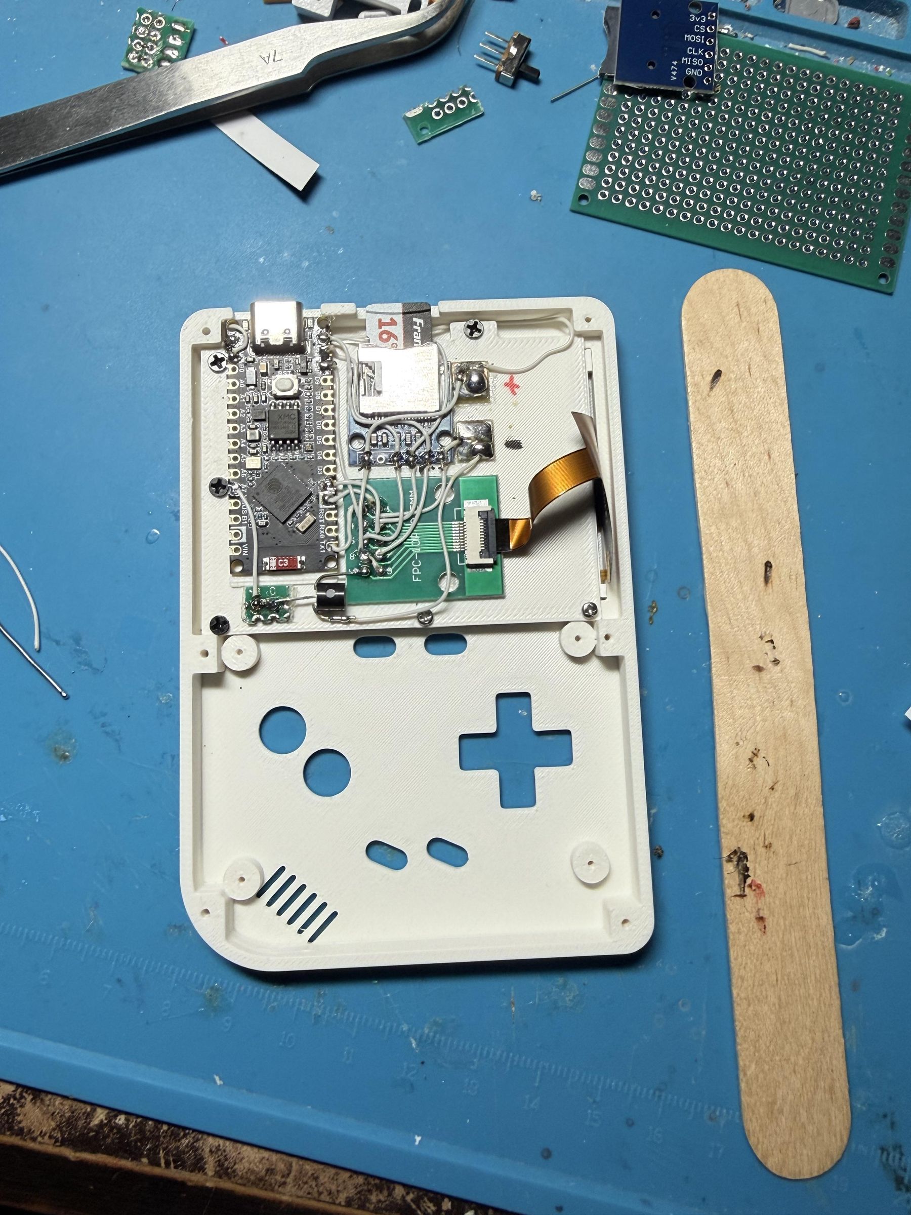
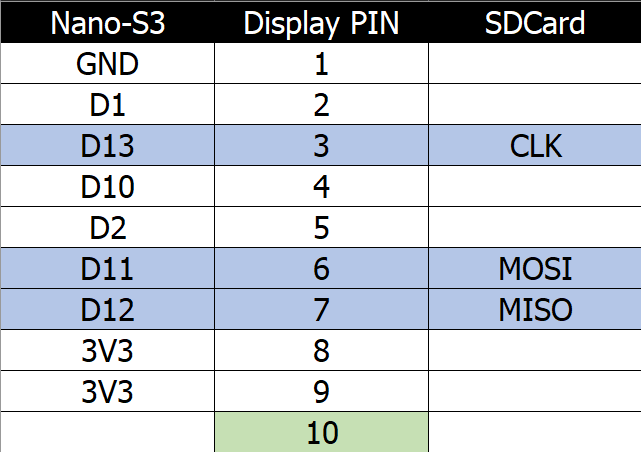
In this step, connect the Nano-S3 to the display and SD card module as follows:
To make the wiring easier to follow, I have created an Excel table. Connect the wires according to the diagram provided. The blue rows indicate connections that share Nano-S3 pins: connect D13 to display pin 3 and the SD card’s CLK pin together. Display pin 10 is the connection to the transistor from the previous step.
Connect the Remaining SD Card Pins to the Nano-S3.
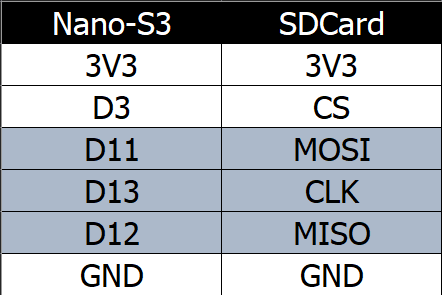
At this point, only the SD card’s CS wire remains: connect it to D3 on the Nano-S3. Connect its 3V3 and GND wires to the shared copper pads prepared earlier.
Prepare the Controls or Joystick Components.
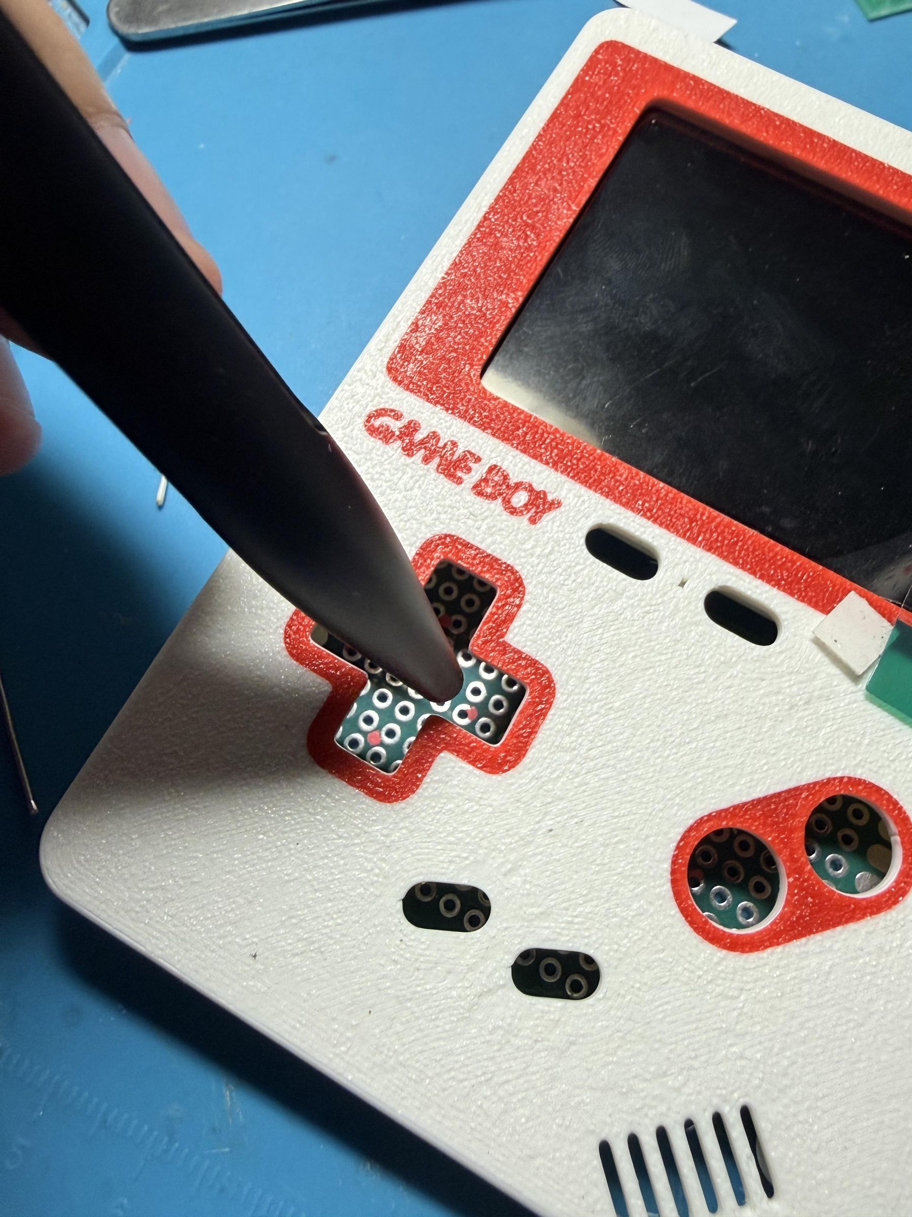
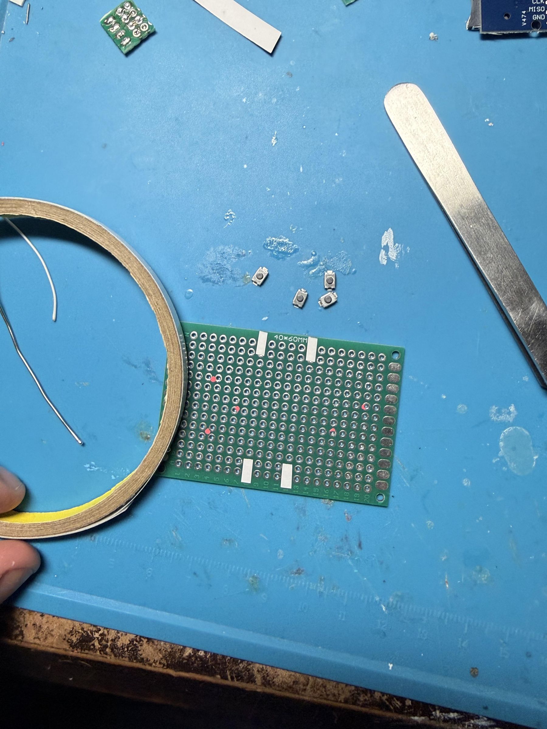
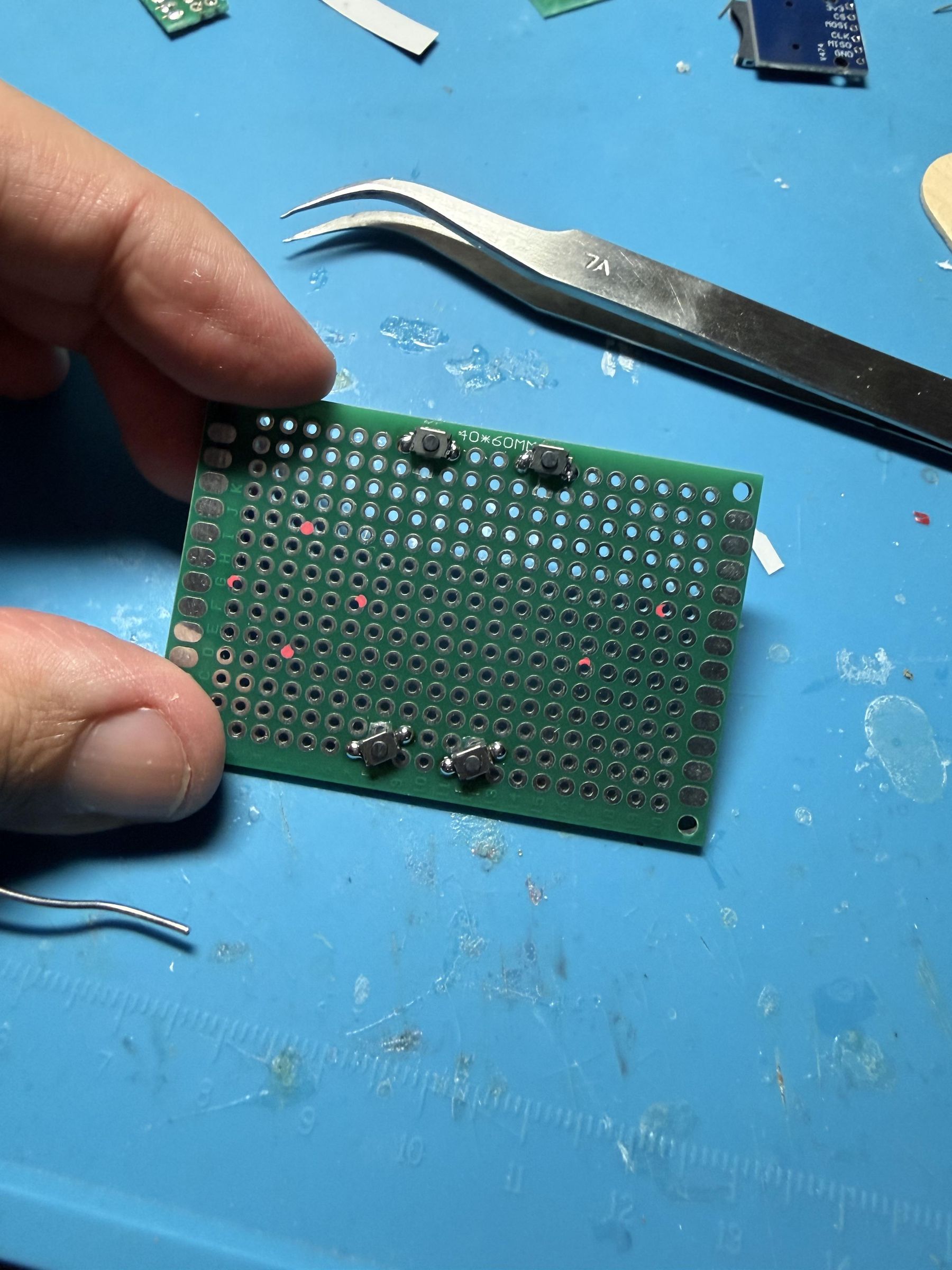
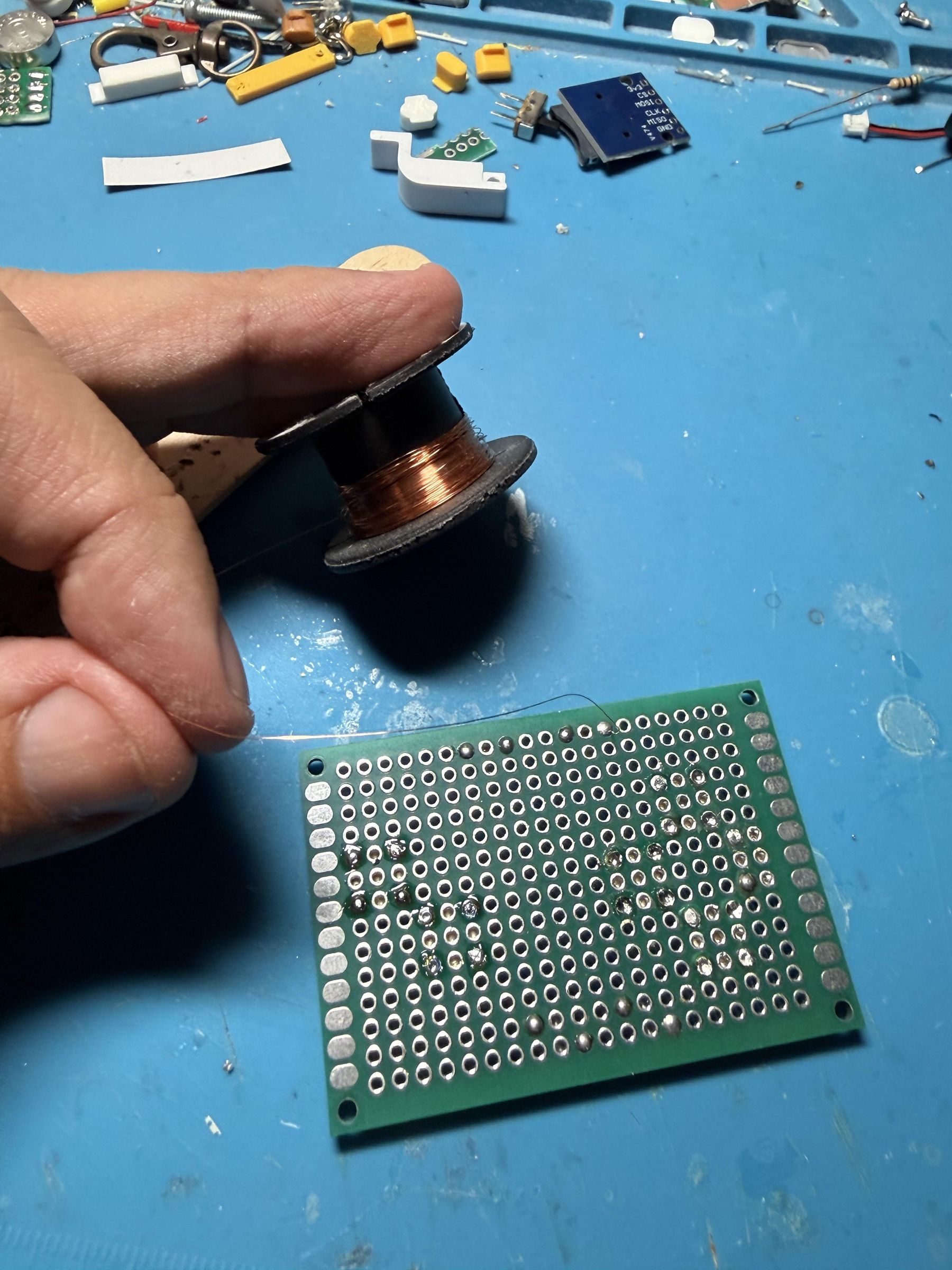
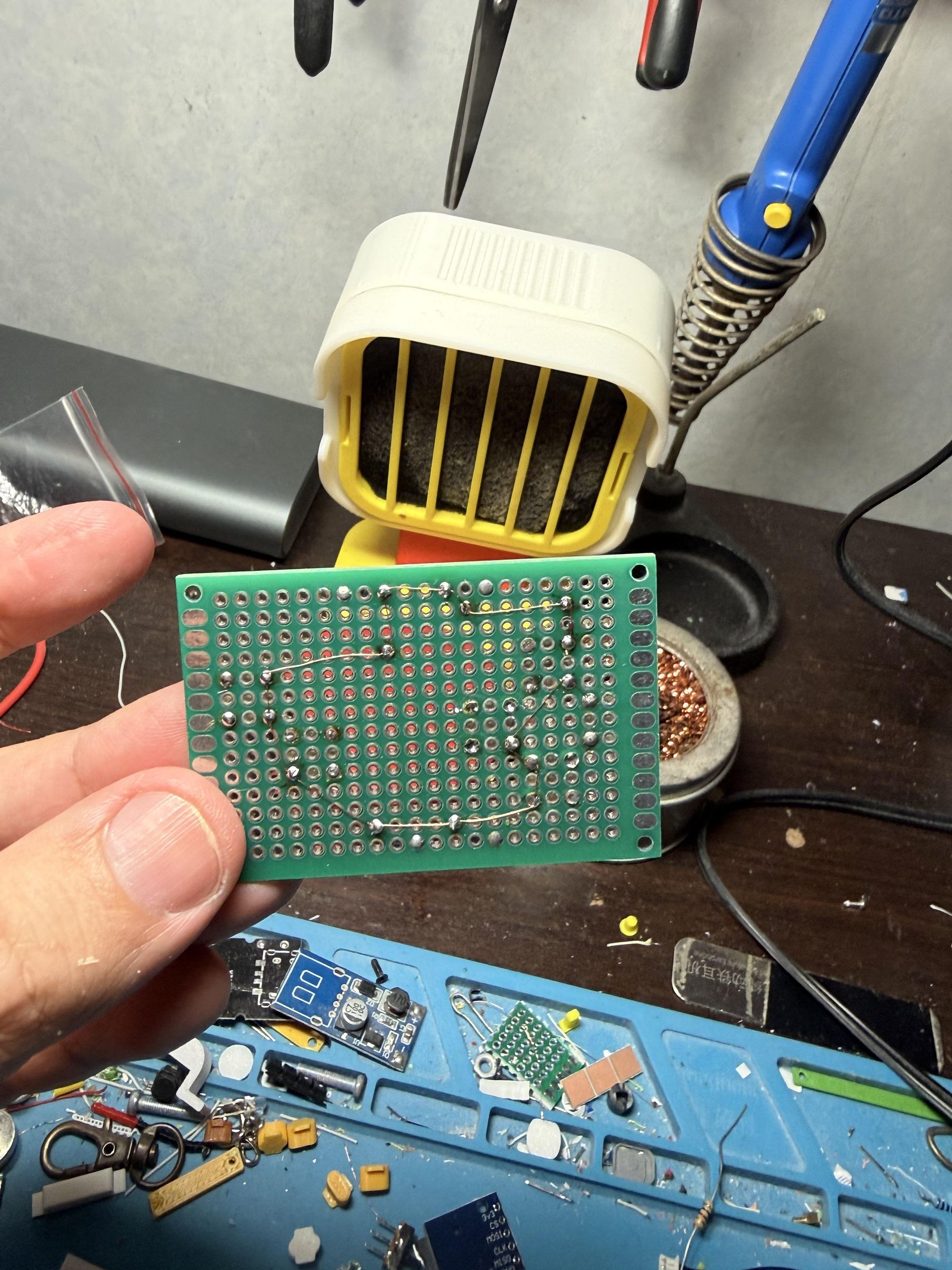
For this step, take the 40 × 60 mm prototype PCB prepared earlier and test-fit it into the front frame. Use two M1.6×3 or M2×3 screws (use whichever fits more securely if one is too loose). I recommend the top-right and bottom-left corners to hold it in position.
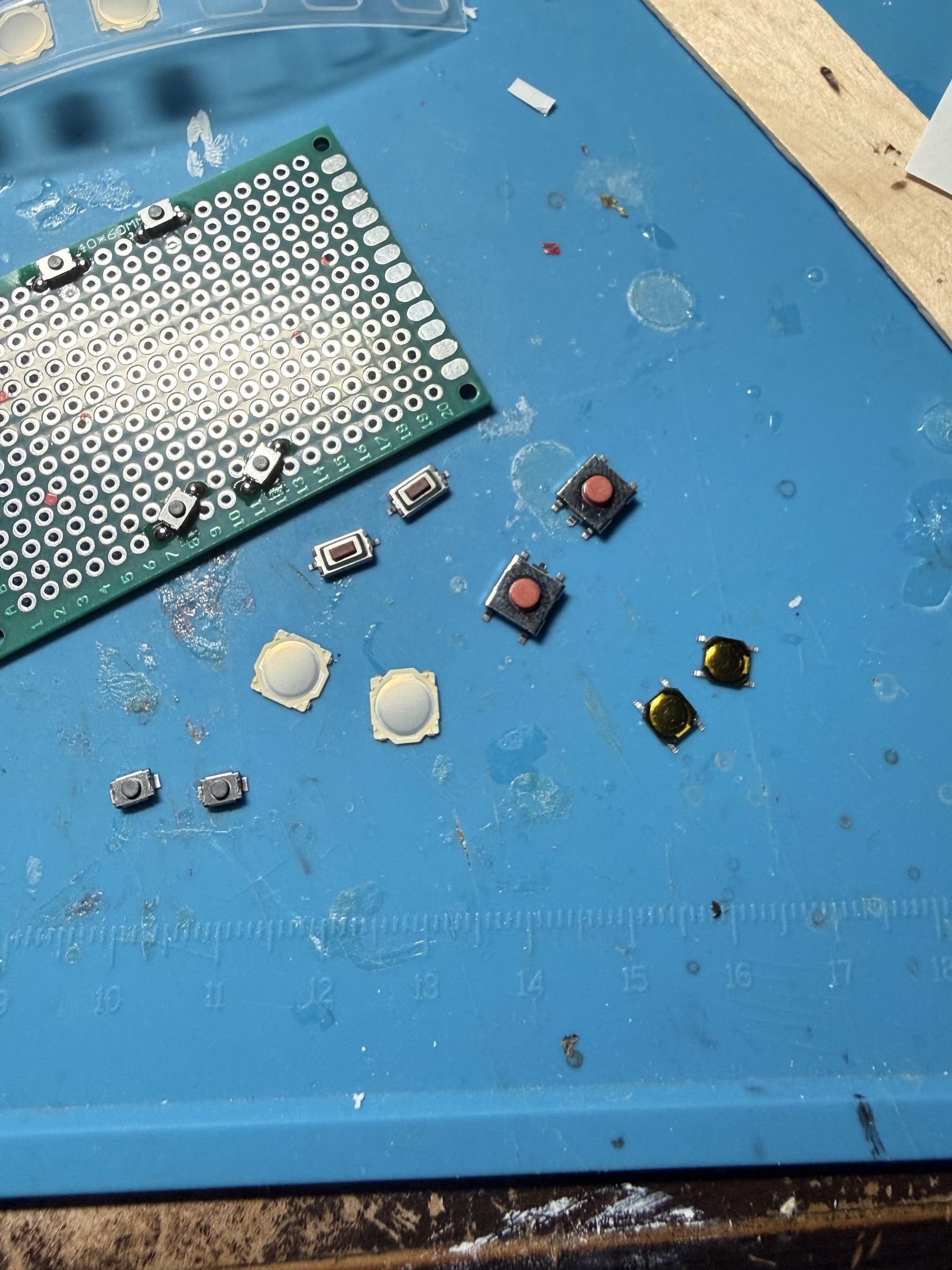
Then turn it over to the front side. Use a marker or pencil that can mark the contact points on the PCB, and mark the positions where the switches will be installed. You do not have to use the same switches I used; you can use other types, such as those shown in the recommended examples. However, if you use switches with push buttons, trim the protruding parts underneath the D-pad and A/B buttons so they can be pressed easily.
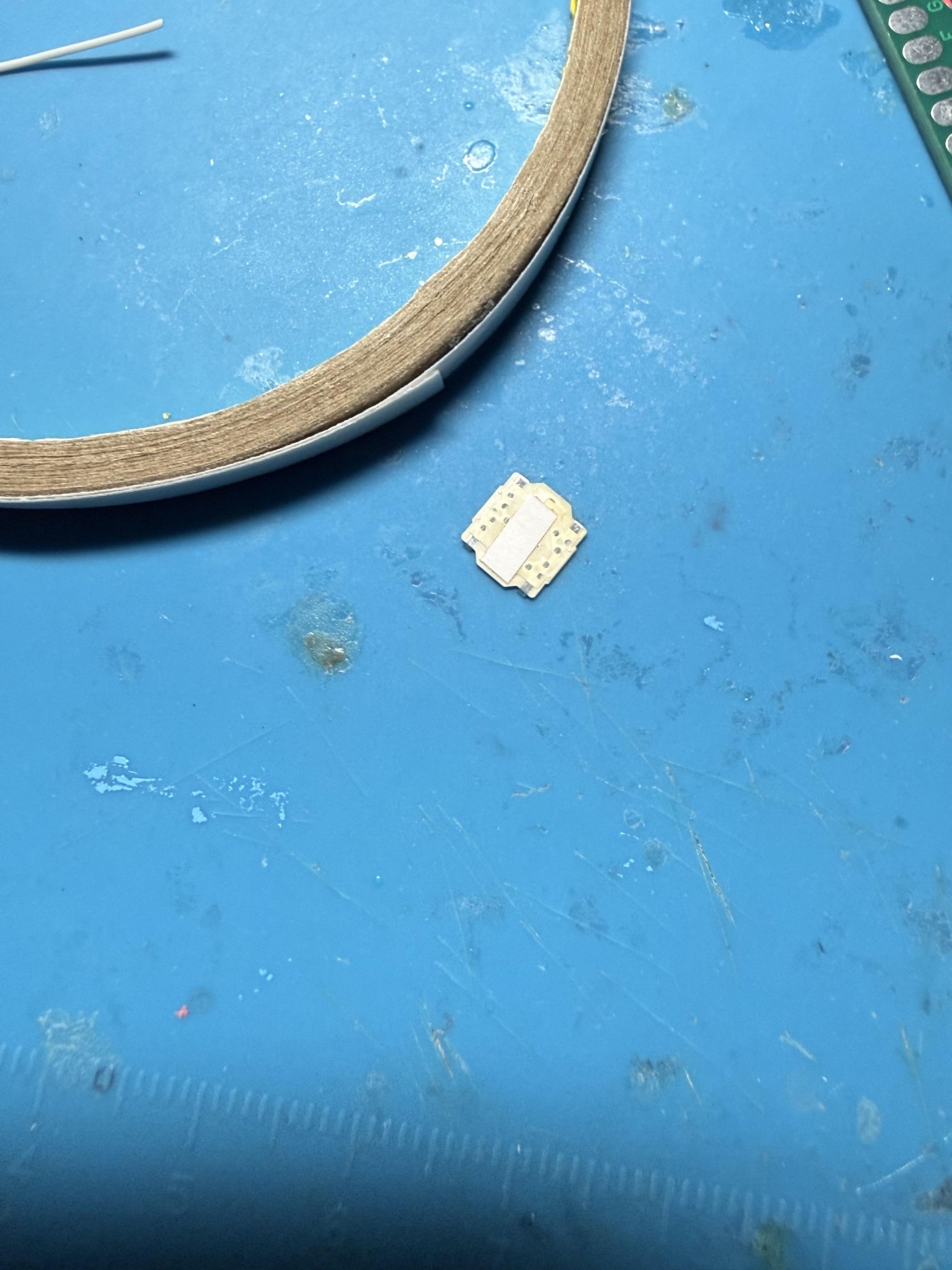
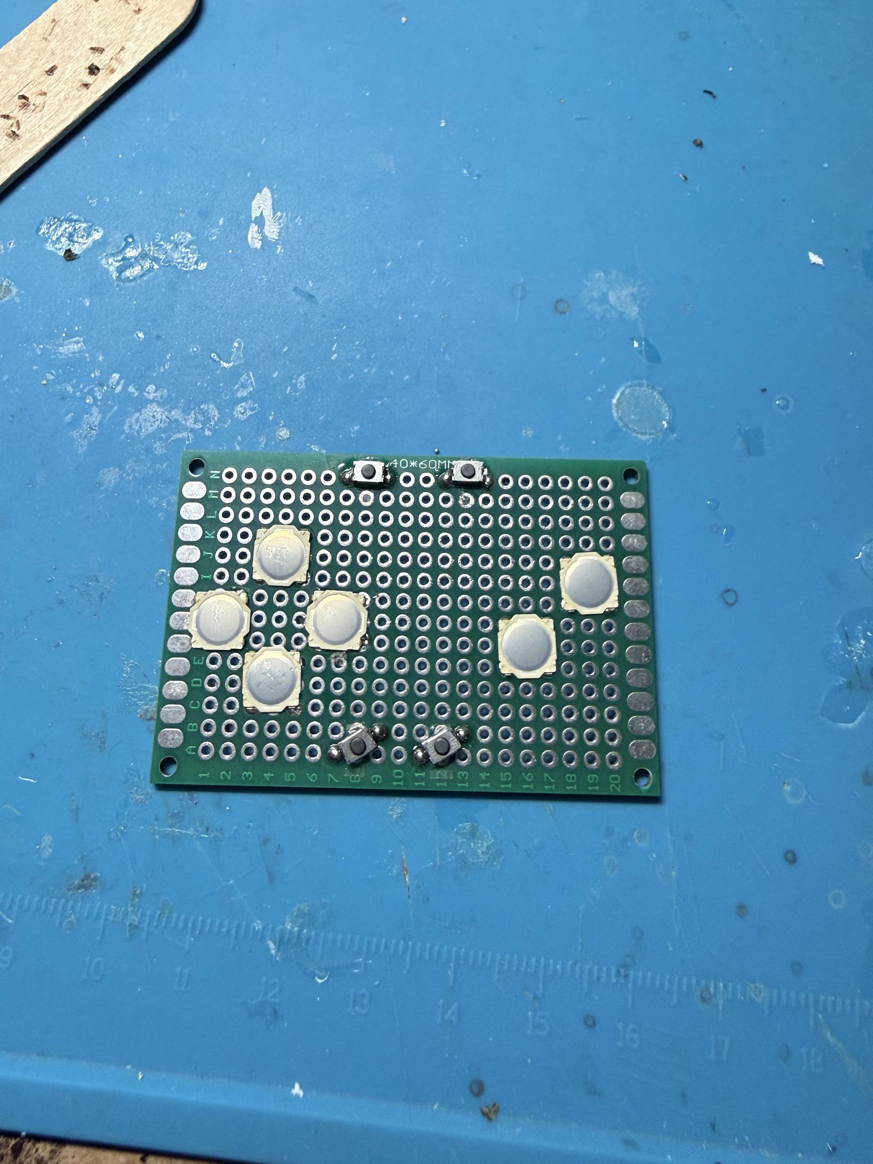
If you use the same switches as I did, apply double-sided tape to their backs as shown to make positioning easier. Place all of them, install the D-pad and A/B buttons, and test the button feel. If they work well, remove them and prepare for soldering.
To solder these switches, add solder to each hole, then insert the soldering-iron tip into the hole to melt the solder and join the contact. Use a multimeter to confirm that each button registers correctly. Repeat this for every button.
Once all switches work, use thin copper wire to connect the ground contact of each switch. You may choose whichever side of each switch is most convenient, but the other side will then be used for the Nano-S3 connection. The insulation coating on this thin wire melts when heated, allowing it to conduct electricity. Hold the soldering iron on the wire briefly to melt the coating, then use it to join the ground contacts of all switches together.
The Connections Are Complete; Prepare for the First System Test.
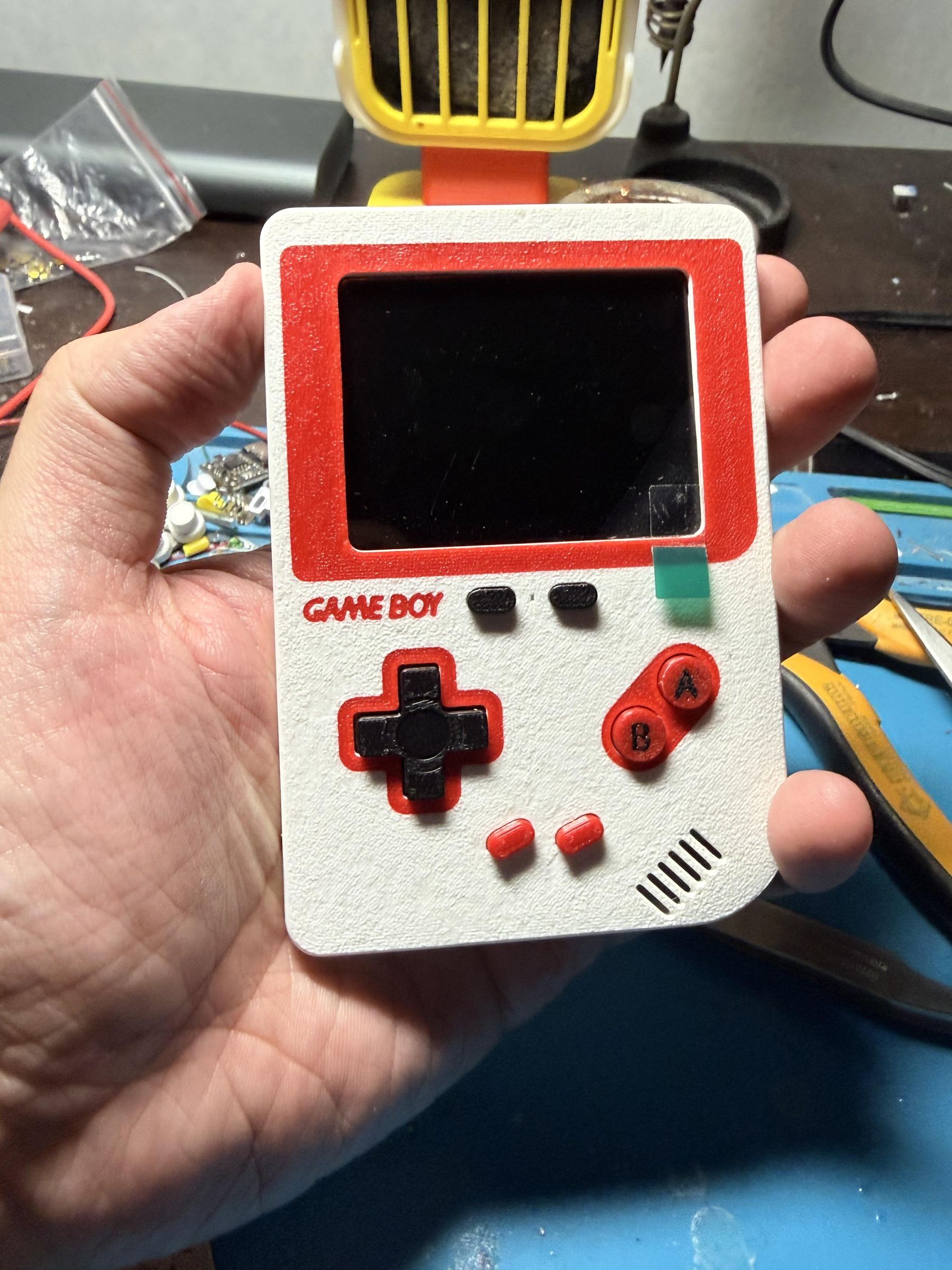
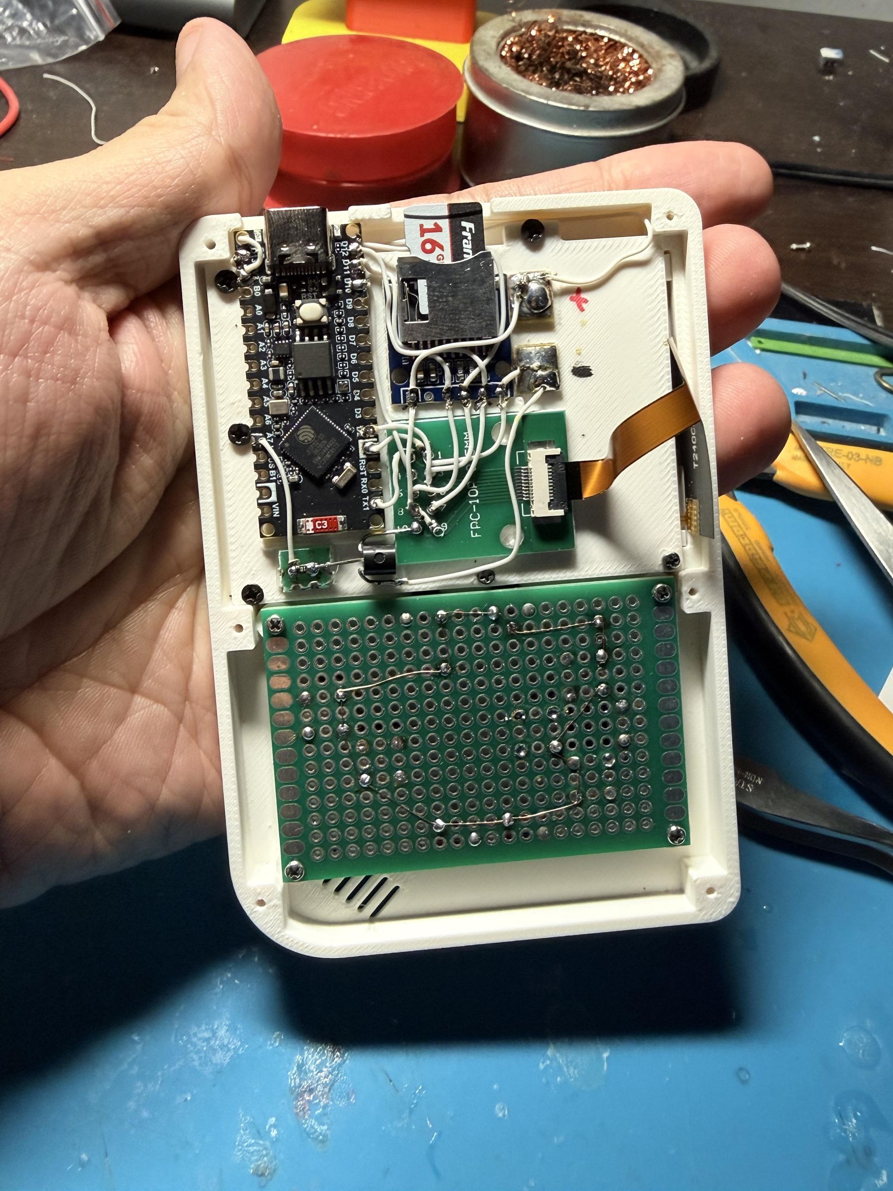
At this point, you can perform an initial display test. Connect a USB-C cable to the Nano-S3 board and check whether it prompts you to insert an SD card. If anything appears on the display, the display wiring is correct. If nothing appears, recheck all display and SD card connections first
Prepare to Connect the Sound Module and All Buttons.
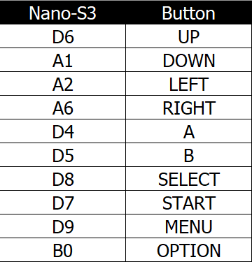
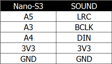
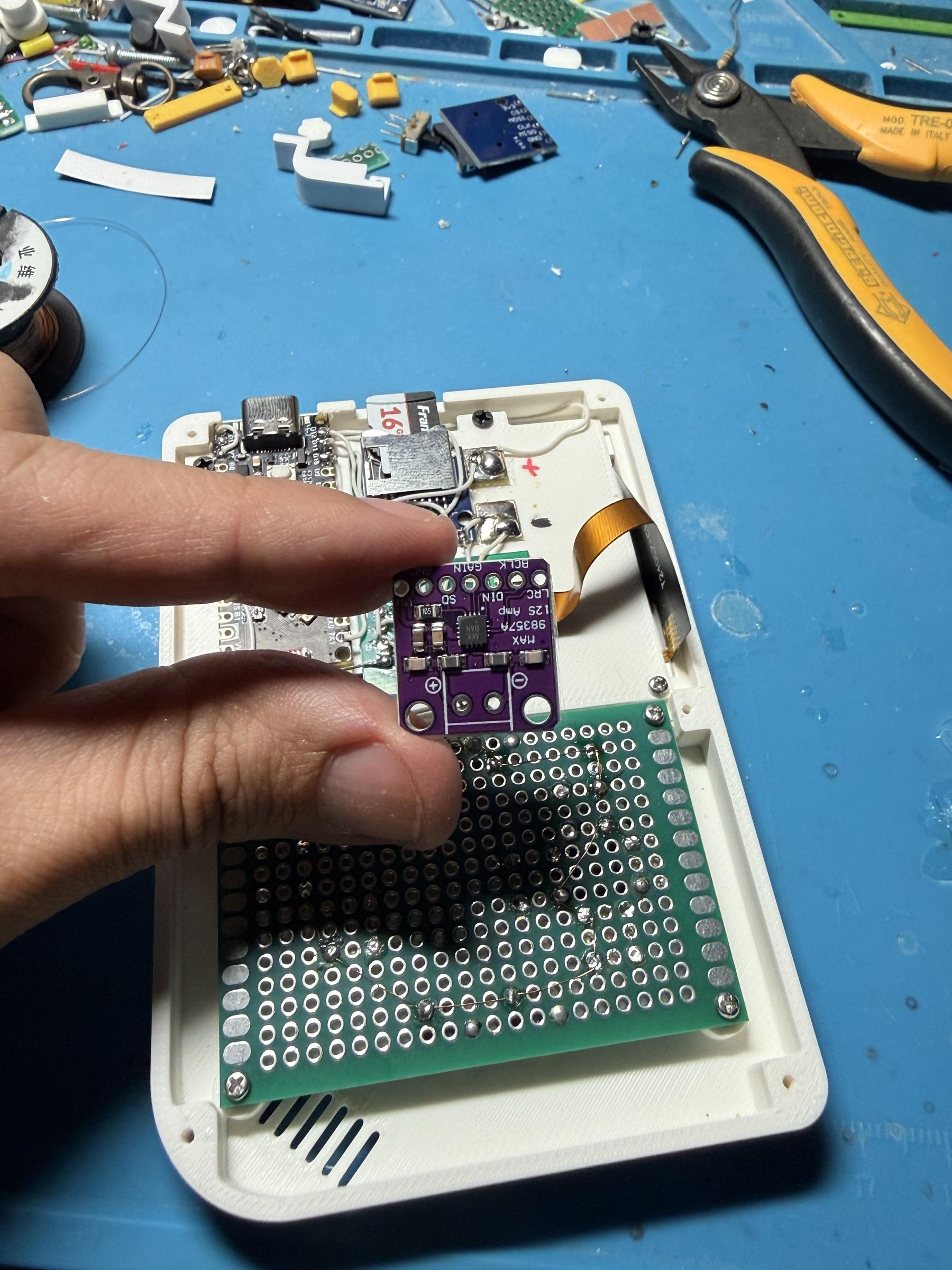
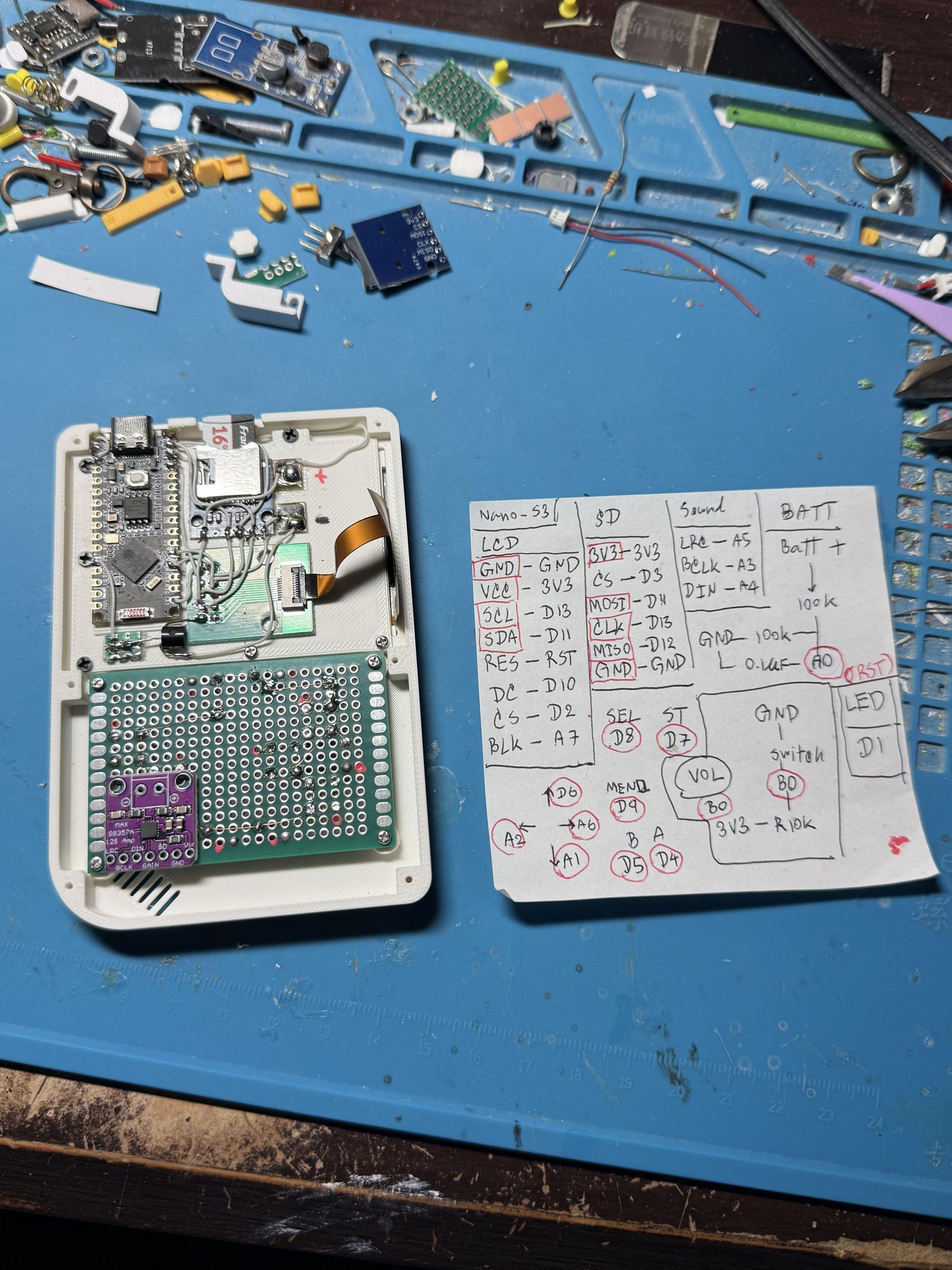
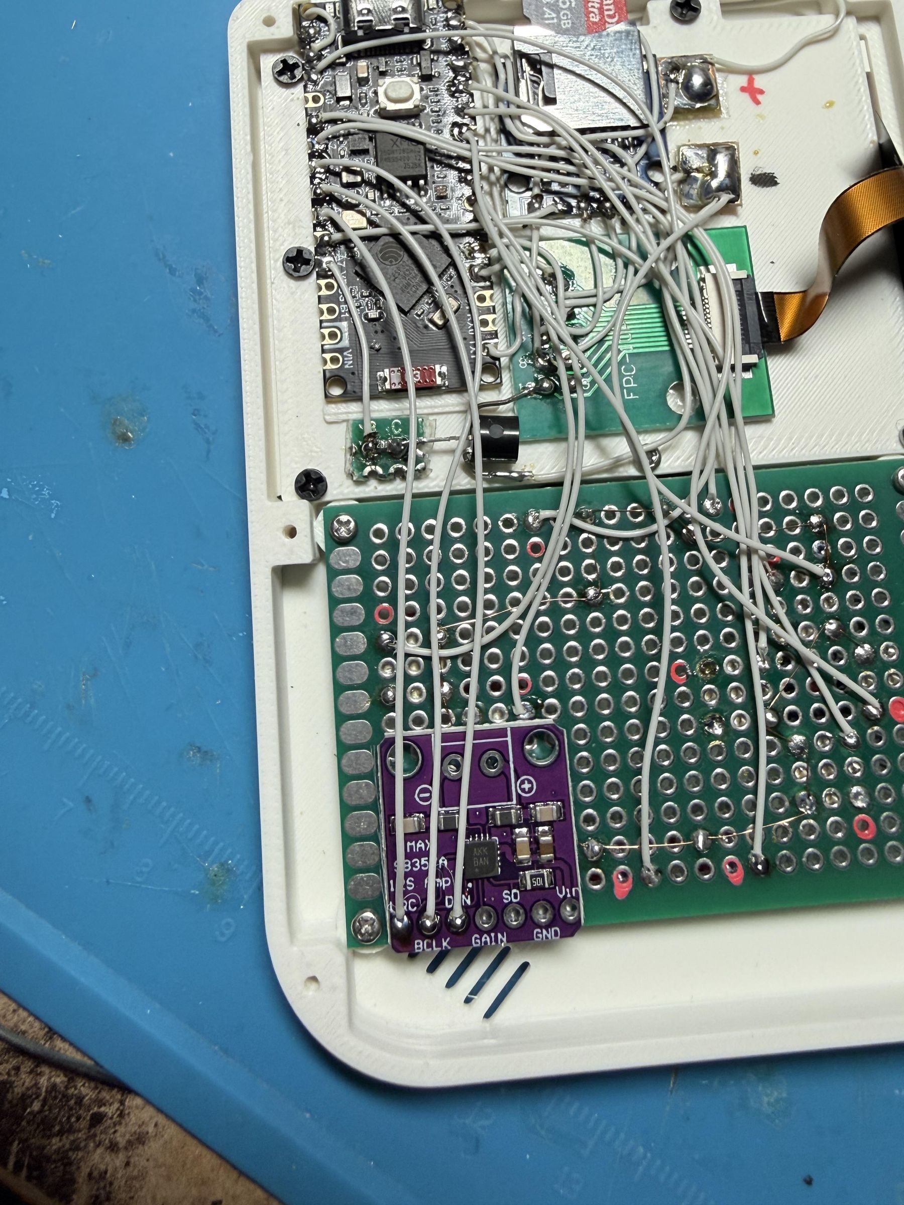
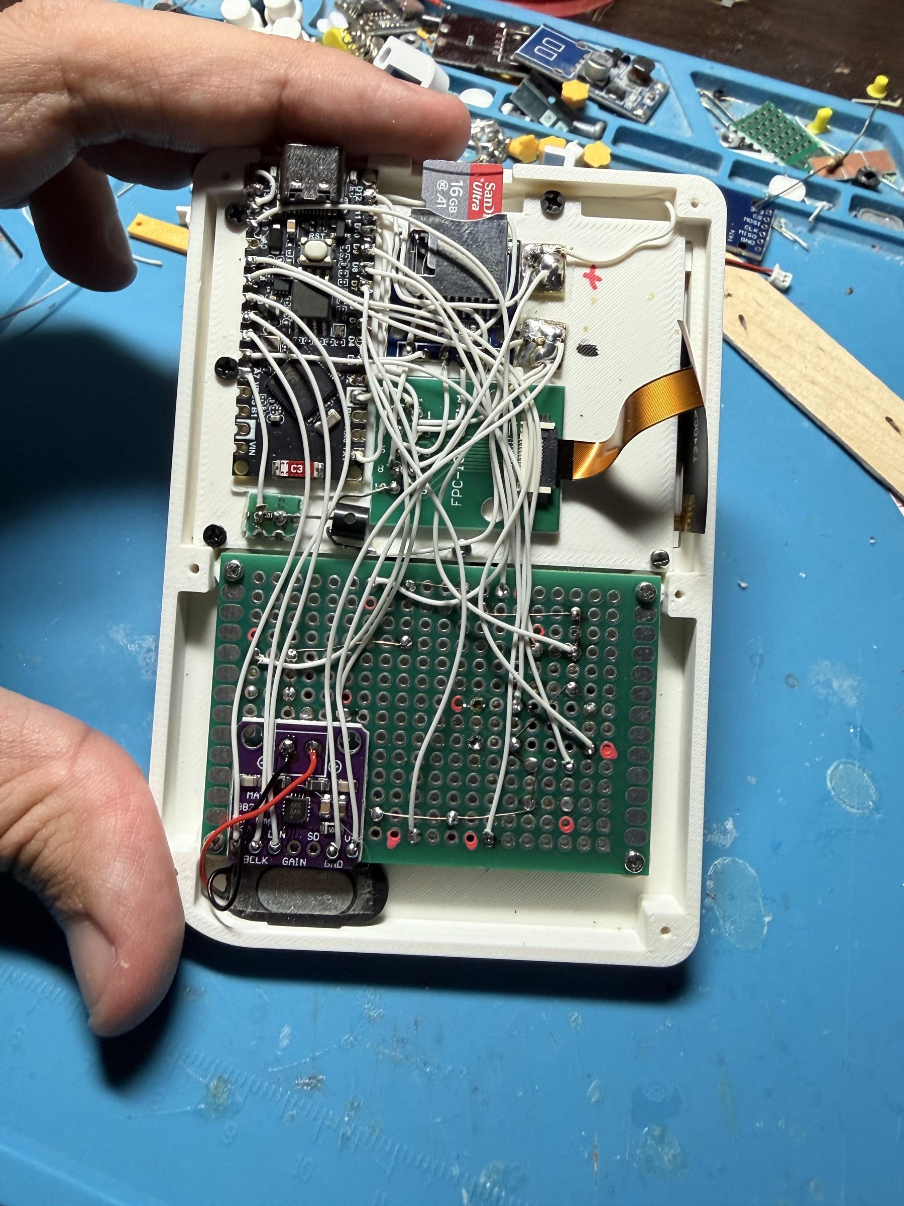
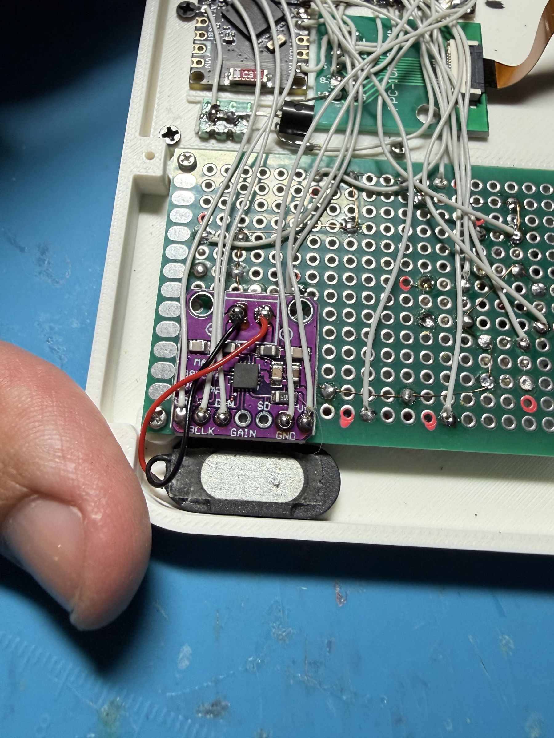
Before this step, I recommend preparing the SD card so testing is easier after connecting the buttons. Format the SD card, then download the SD card files from this tutorial:
tutorial page: https://www.instructables.com/ESP32-VMU-Handheld-Console-Yes-It-Plays-Doom/
Direct link: https://github.com/DynaMight1124/retro-go/releases/download/VMU/VMU-S3.SD.Files.zip
Unzip the files directly to the SD card’s root directory, then add a few ROMs to test that everything works.
Connect the buttons to the Nano-S3 according to the pin assignments in the Excel table. Do not forget to connect the PCB’s joined ground line to the common ground prepared earlier.
Then connect the sound module to the Nano-S3 according to the Excel table. You can mount the speaker in the lower-left corner, at the sound outlet opening.
At B0, which is connected to the Option button, connect a 10 kΩ resistor between 3V3 and B0. This connection prevents the input pin from floating; it acts as a pull-up resistor.
[ Once everything is connected, you are ready for an initial test. Plug a USB-C cable into the Nano board and try using it. If all connections are correct, it should work.
Let’s Work on the Battery Section.
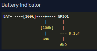
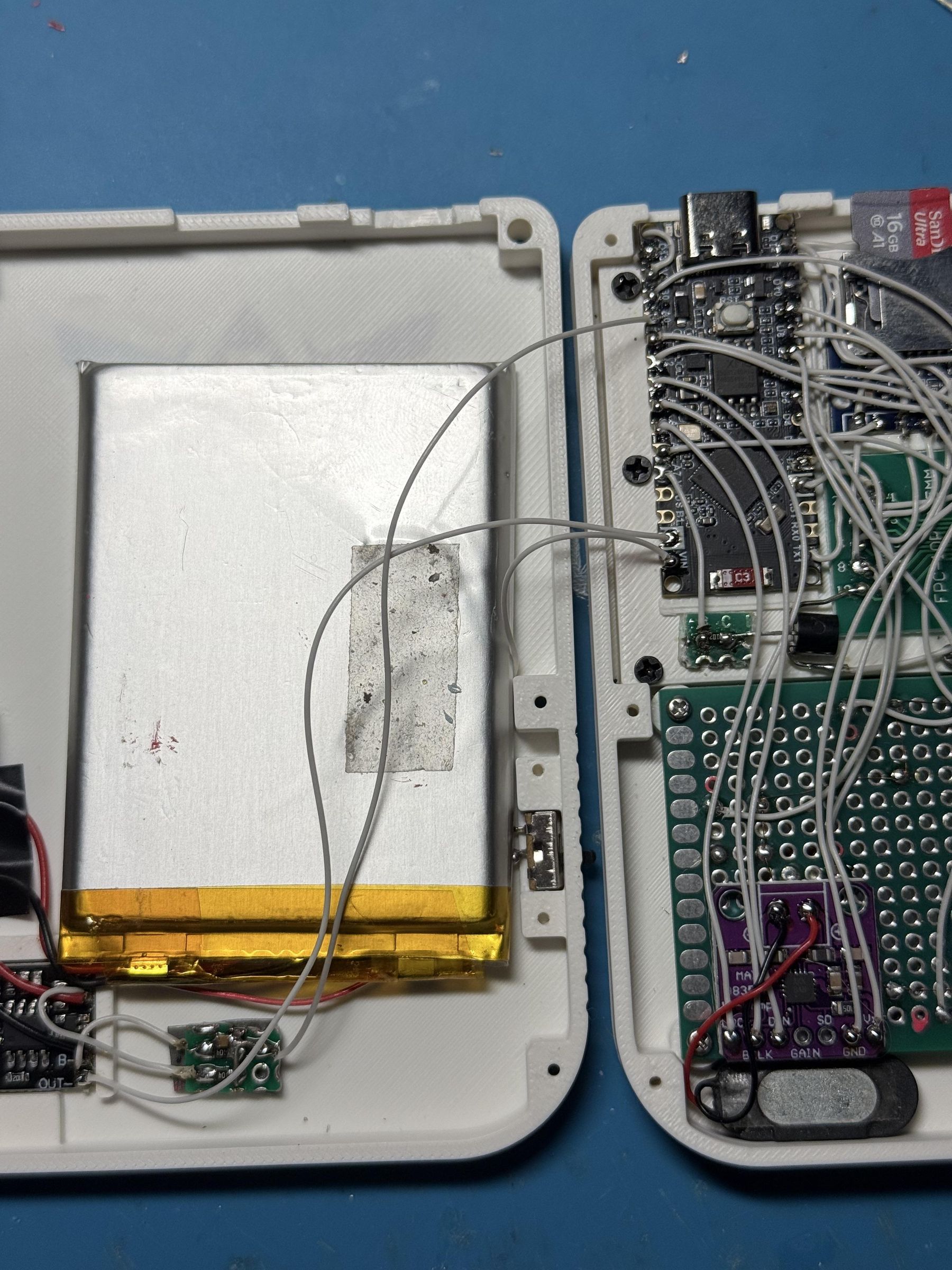
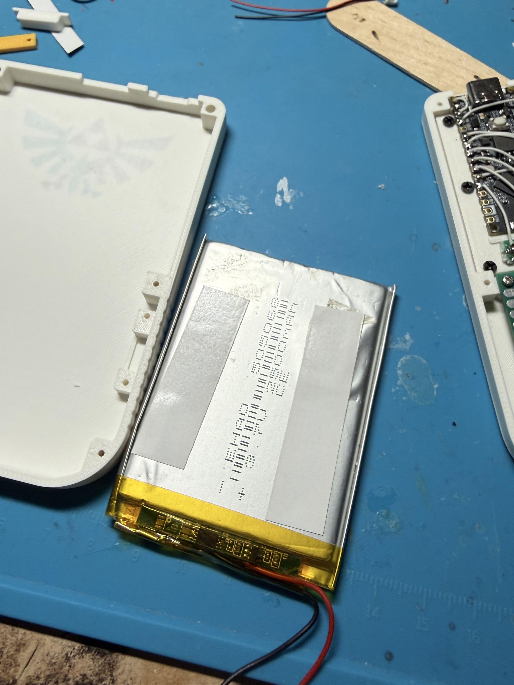
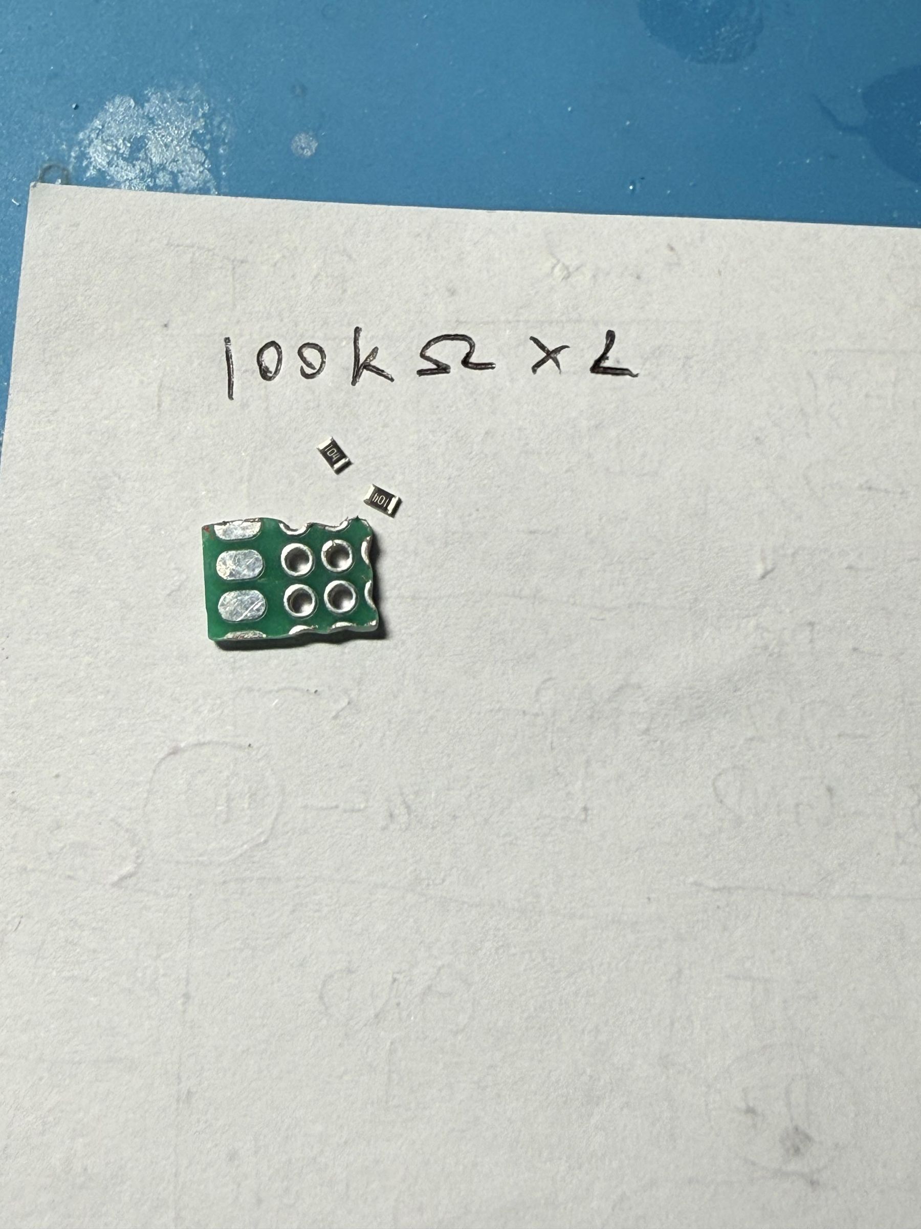
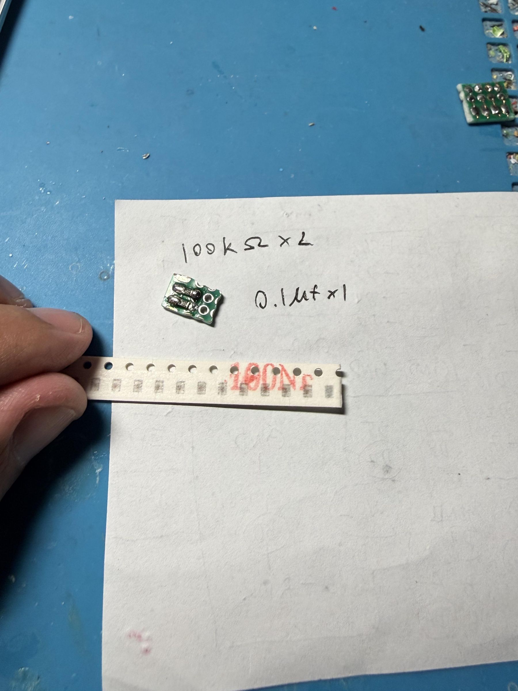
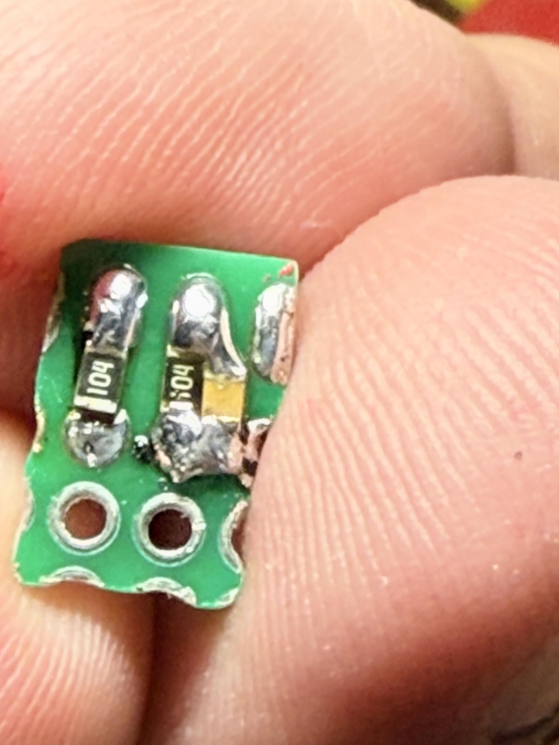
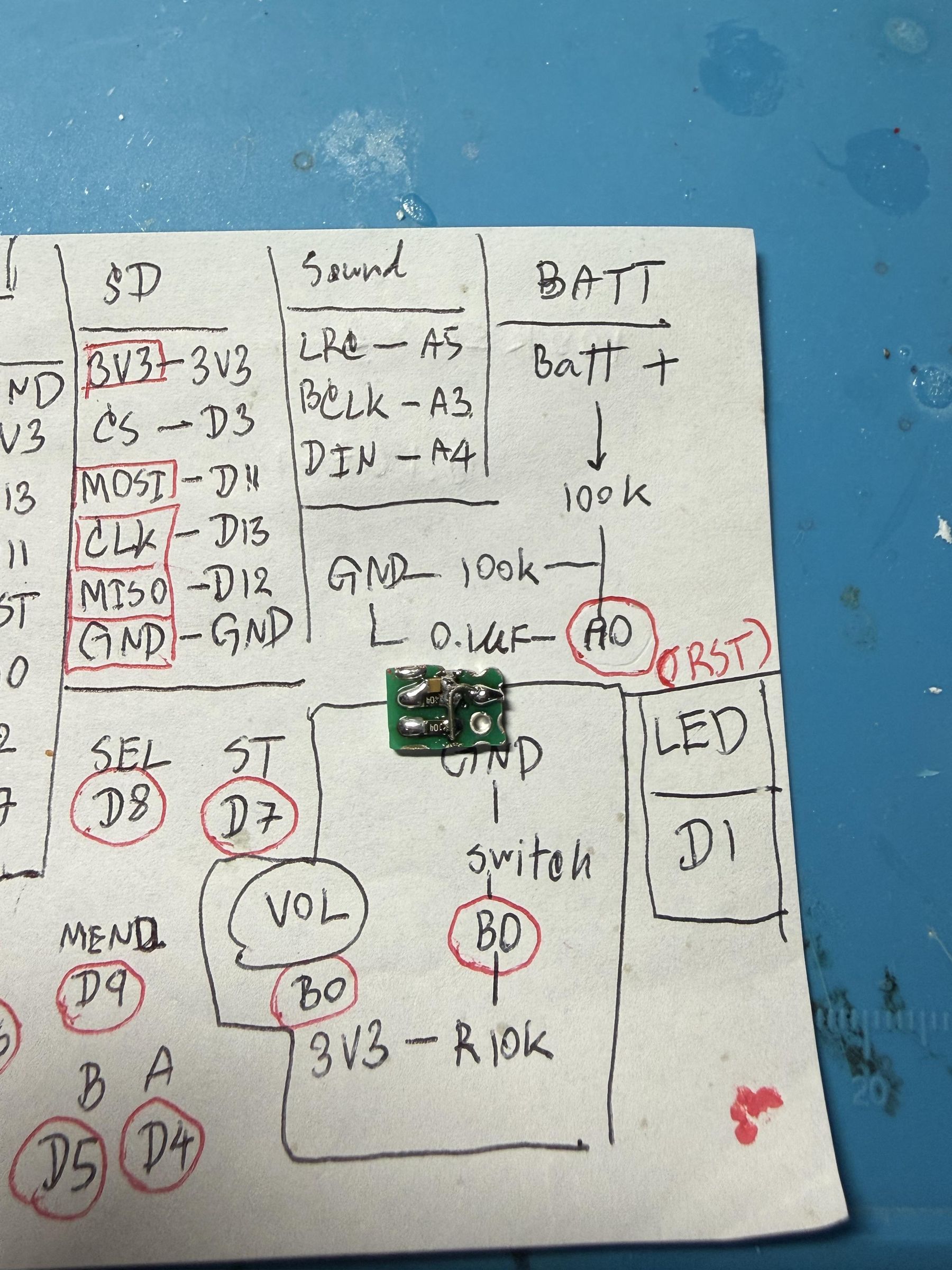
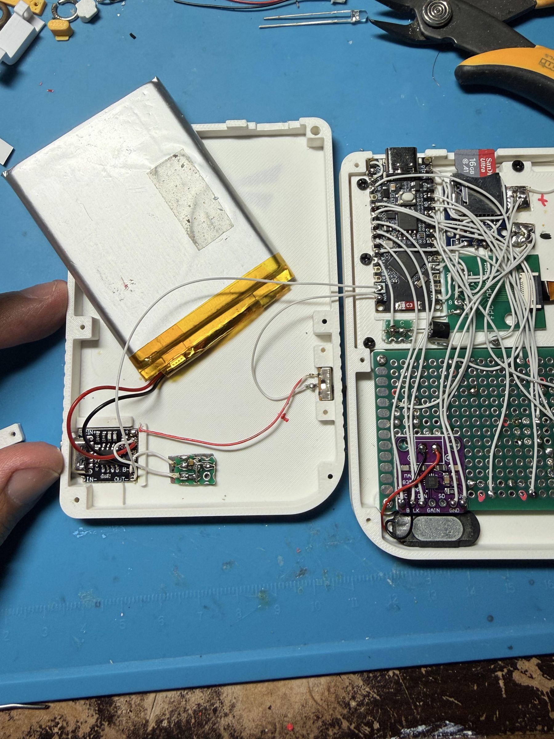
Start by applying double-sided tape to the LiPo battery (I am, of course, a big fan of double-sided tape). Next, build the battery-monitoring circuit. Use two 100 kΩ resistors and one 0.1 µF capacitor. Mount the two 100 kΩ resistors in parallel on a cut piece of PCB, and connect the capacitor in parallel with either resistor. Join one end of both resistors and the capacitor together; connect this point to the Nano’s A0 pin to read the battery signal. Connect the other ends of the two resistors to the LiPo battery terminals—one resistor to positive and the other to negative.
After completing the battery-monitoring circuit, connect both it and the battery to the charging module, then place the module in the charging compartment as shown. Don’t forget to connect pin A0 to the battery-monitoring circuit you built. Now, if it's connected correctly, it should be working. Try turning on the switch and playing it right away.
Close the Lid and Finish the Hardware Assembly Process.
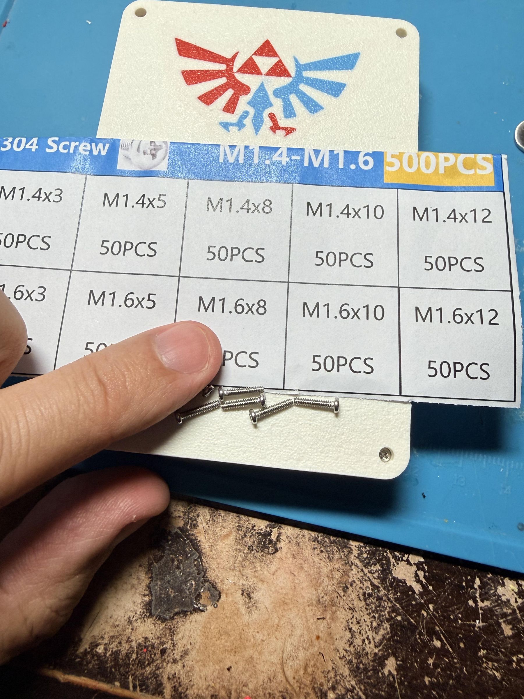
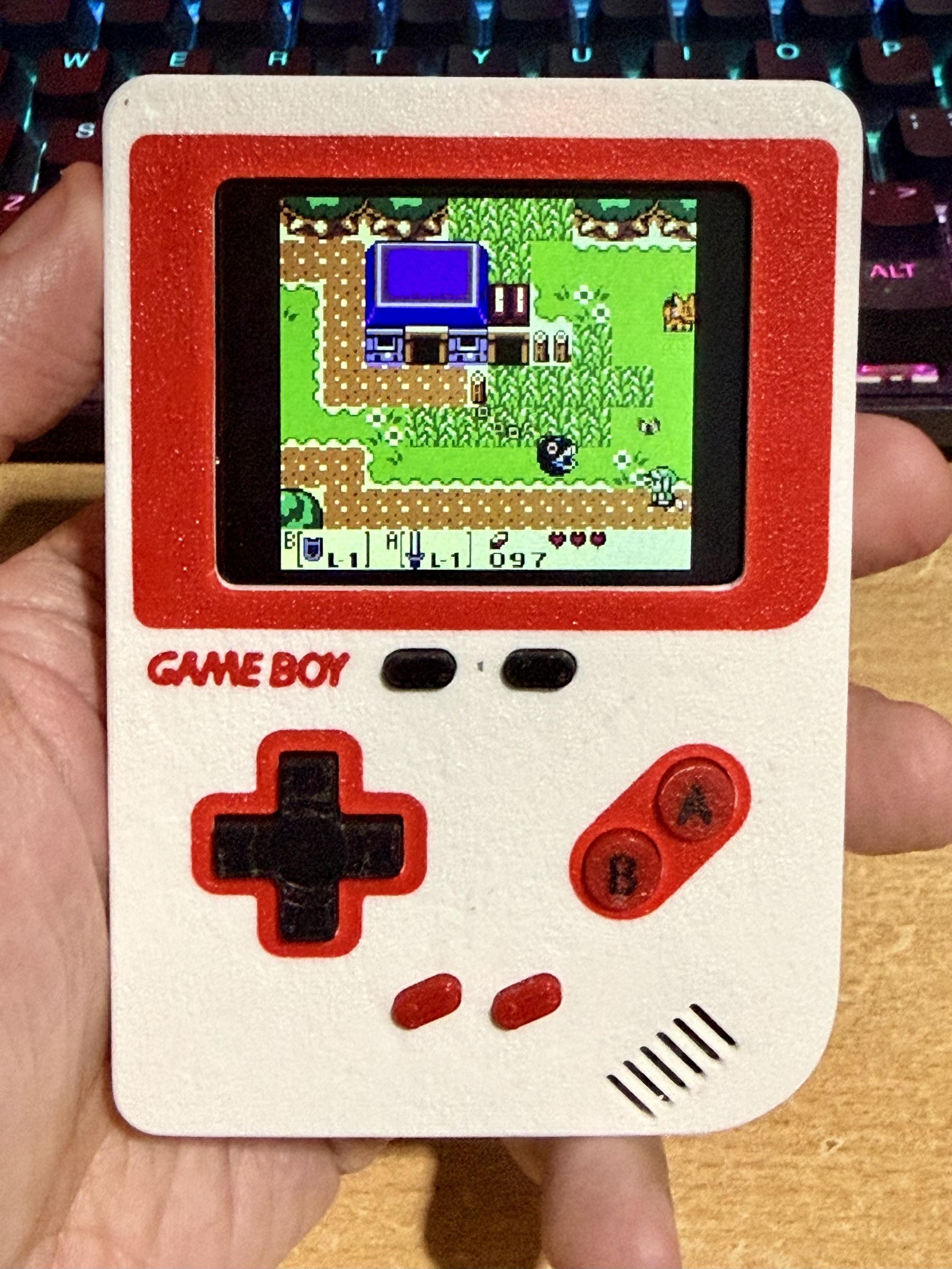
Use 6 M1.6x8 screws to close the lid. During this step, be very careful with the wires so they don't get in the way of the body or the screw holes.
Software Side
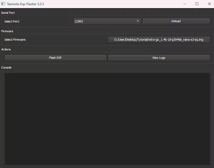
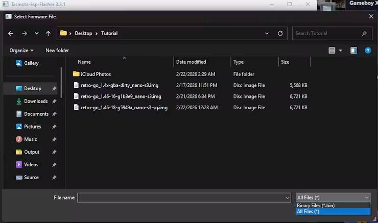
Since I'm feeling a bit lazy, I'll just copy and paste what I wrote in another tutorial :P
- Start by loading the firmware I provided first. https://drive.google.com/file/d/1TjKZ-cES3WcjlKK0p2flfuJO0PffLL3C
- Load the ESP Flasher tool. https://github.com/Jason2866/ESP_Flasher/releases
- Run the program, and you should see a screen similar to the pictures.
- Connect the ESP32-S3 Nano to your PC, then click Reload once. After that, select the ESP32-S3 port—in my case, it shows up as COM5.
- Click Browse to Select Firmware. select .img (You may need to change the file filter at the bottom-right corner to All Files (*) )
- Click Flash and wait.
REF
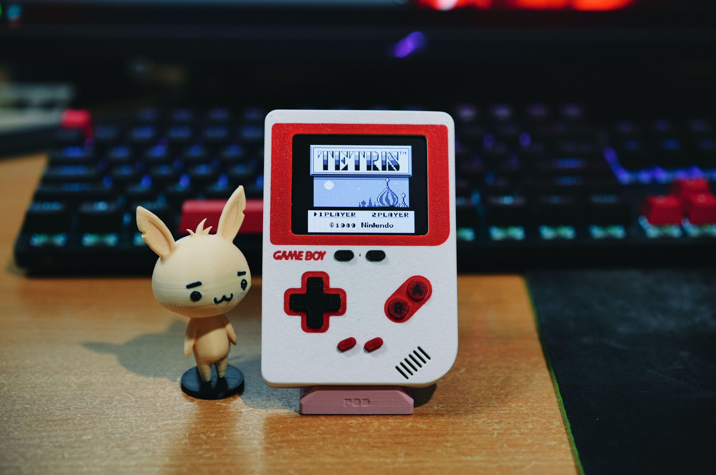
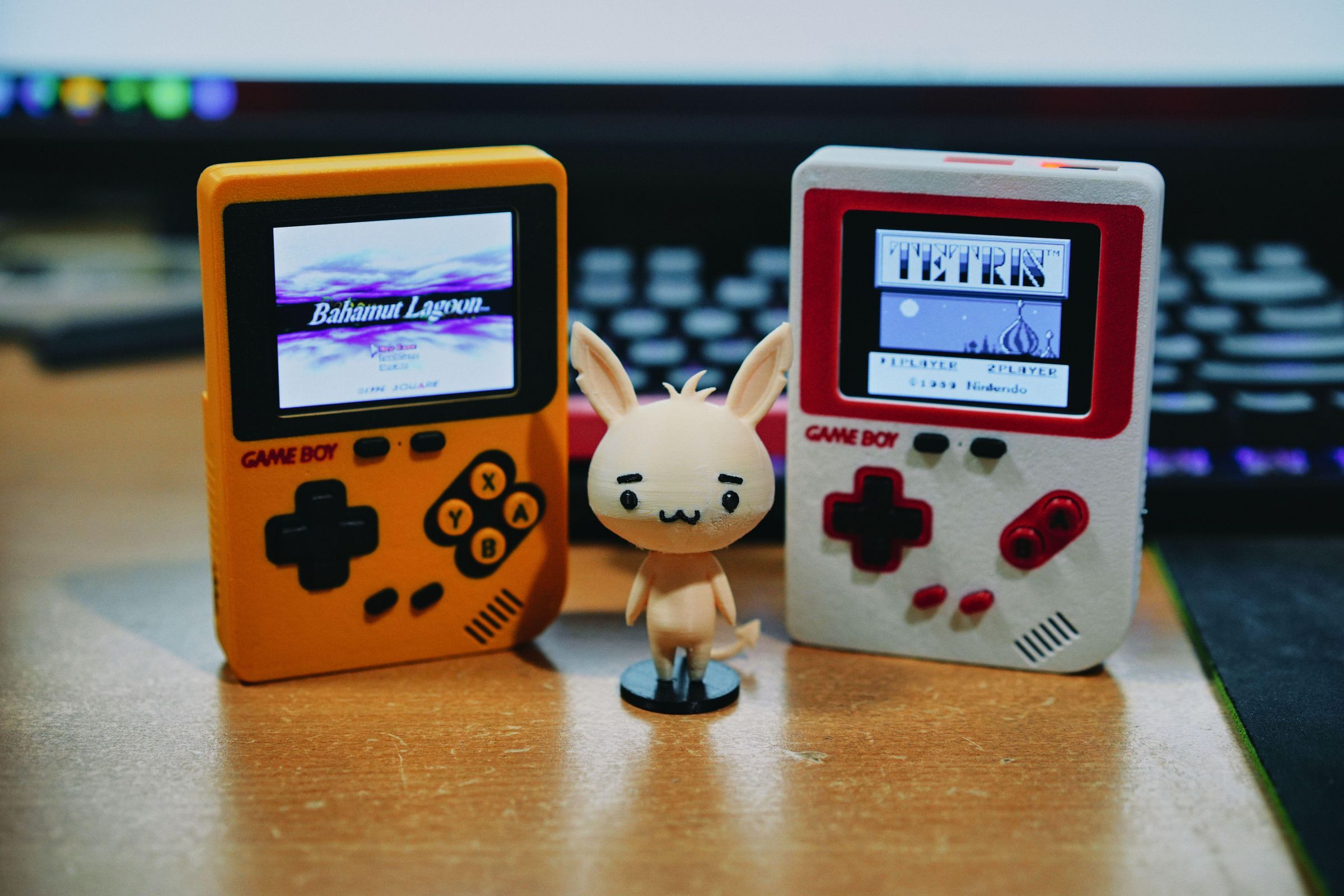
The references I used for this project, including the firmware I created, are built upon these links.
* A YouTube video in Thai, in case anyone wants to see how it works.
Retro-Go: ducalex/retro-go: Retro emulation for the ODROID-GO and other ESP32 devices
ESP32 VMU: ESP32 VMU Handheld Console - Yes, It Plays Doom! : 11 Steps (with Pictures) - Instructables
Retro-Go S3 nano: Retro Game with Retro-Go S3-nano - Hackster.io
ESP Flasher for flash .img: Releases · Jason2866/ESP_Flasher
Actually, I modified this from the SNES version that I made just for fun, so I didn't save the code. Anyway, if anyone wants to take it and modify it further, you can check out this GitHub repo of mine.