Garage Door Alarm and Auto-Closer in a Photo Frame (with Wireless Communication)
by SébastienL42 in Circuits > Arduino
5273 Views, 66 Favorites, 0 Comments
Garage Door Alarm and Auto-Closer in a Photo Frame (with Wireless Communication)


Why?
Have you ever forgotten to close your garage door? Or accidentally pressed the garage door remote control button in your pocket without realizing it?
With this device, those worries are over! Keep thieves from entering your garage—and potentially your home, if it connects to your garage.
Features
- Immediate notification when the garage door opens (via a gentle LED indicator and a short buzzer sound).
- A reminder if the door remains open for too long (with a blinking LED and an alarm buzzer every minute).
- Automatic door closing after a longer period, if you leave home (optional, depending on your garage door setup).
- Ability to mute the alarm and auto-close if you need the door to stay open (simply press a button to enter the "Muted" state, indicated by a different color LED. Press the button again or close the door to exit the muted state).
Design Decisions
The device must be TRUSTWORTHY:
- Warn as soon as the door is even slightly open:
- As thieves can enter through the garage (and possibly home) a partially open door.
- Position the sensor strategically.
- Inform about the system’s state at all times:
- Powered on / operational / everything is good
- Door open
- Muted alarm
- Connection problem
- Status alerts via LEDs and sound (buzzer).
- Ensure ease of use with intuitive status indicators.
- No false negatives:
- No batteries: plug the modules into a power source & never worry about missed alerts because some batteries were dead (Plug-and-Play / Plug-and-Forget / No Maintenance / No Worries).
- Provide alerts for lost connections.
- Automatically close the door:
- As an option, if your garage door allows it
- Provide no way to open the door:
- The device is too easily piratable: do not introduce such (technical) security breach as the device is only supposed to close existing (human) security breaches
- Ensure bug-free code:
- There are a lot of sounds and LED blinking modes, each triggered by events that can preempt previous states: it can be a source of bugs
- Add some structure to the code:
- Some Functional Programing philosophy, to recompute the core state in a predictable way
- Some Object-Oriented Programing philosophy, to enforce separation of concerns
- => there is a small learning curve
- => but the code is easy to reason about, and clear enough to be pretty sure there is no bug
- => concepts should be familiar to developers accustomed to modern frontend and backend development
It must also be EASY TO BUILD AND INSTALL:
- The monitoring and control module should not have to be near the garage door:
- Use wireless communication to avoid drilling holes in walls.
- Ensure the hardware is easy to obtain:
- No reusing of some esoteric remote control circuit leftover
- Keep the project budget-friendly.
Supplies
Electronic parts:
- Main electronics:
- 2x Arduino Nano Every Main Control Board
- 2x NRF24L01 Wireless Transceiver Module + its power Regulator
- LEDs:
- 1x red LED
- 2x yellow/orange LEDs
- 1x green LED
- 1x blue LED
- 2x white LEDs
- Resistors:
- 5x 100Ω resistors
- 1x 330Ω resistor
- 2x 1kΩ resistors
- 2x 2kΩ resistors
- Capacitors:
- 2x 10µF capacitors
- 2x 0.1µF capacitors
- 1x 47µF capacitor
- Push buttons:
- 2x yellow/orange buttons
- 2x green buttons
- 1x blue button
- Other electronic components:
- 2x passive buzzers
- 2x relays
- 2x limit switches
- A few meters of about 18AWG cables
- Electricity:
- 5x screw terminal blocks + 3x screw terminal blocks
- 2x USB chargers
- 2x micro-USB (type B for official Arduino Nano Every) to USB-A cables
- A few meters of electric cables (depending on the size of your garage and where you place the controller)
For the photo-frame dashboard housing (indoor module):
For the door-controller housing (the garage-side module):
- 1x IP65 waterproof plastic junction box (not metal, to not block radio signals)
User Guide


Before building the project, let's check how it will work once finished, so you can decide if it fits your needs or if it is not suitable for you.
Please download the user manual PDF below (available in both English and French). They are comprehensive and cover all possible device states (light signals, blinking lights, sound alerts, button roles, special button combinations, and troubleshooting errors indicated by blinking LEDs).
Video 1: Here's a more visual experience demonstrating standard functionality:
- On the controller, you can open the garage by pressing the green button (this button is connected directly to the motor and operates outside of the Arduino circuit for safety reasons).
- The dashboard (photo frame) lights up red to indicate that the door is open.
- The demo mode is activated for this video: state transitions occur in seconds instead of minutes.
- After a while, the red light flashes to remind you that the door is still open.
- The garage unit alerts you to the door's imminent closure with a sound.
- The green LED lights up as the controller attempts to close the door.
- Then, the green LED lights up again to indicate that the door was automatically closed in your absence.
- If you wish to keep the door open, press the yellow button (on either device). This action prevents reminders about the door being open, and the door will not close automatically.
Video 2: Button press combinations:
- Hold the blue button and press the other buttons to increase or decrease the notification volume.
- Press the blue button for 5 seconds to activate demo mode (quick state transitions in a matter of seconds, to demonstrate the device's functionality to others).
- Press the blue button again for 5 seconds to disable demo mode (restores normal state transitions, which take place over minutes).
- Press the blue button for 10 seconds to enable the build mode: all LEDs will light up, allowing you to adjust resistors to match LED brightness.
- Not shown in the video: Quickly press the blue button four times to mute sounds until the next door closing (press it four times again to re-enable sounds).
Video 3: Disconnected controller:
- If the controller cannot receive a signal from the dashboard, the white LED flashes.
Video 4: Disconnected dashboard:
- If the dashboard cannot receive a signal from the controller, the white LED flashes.
Your Garage Door Motor Probably Allow Controlling It


The project will automatically close the door after a certain period.
👌 No worries about security: several measures ensure that the Arduino will never mistakenly open the door—it will only close it:
- Not connected to the internet or Bluetooth.
- The door will never be commanded to open if it is already closed.
- Redundant sensors prevent a faulty sensor from making the Arduino think the door is closed when it isn’t.
- Redundant relays ensure that even if one relay fails, it cannot open the door.
- If door closing fails, the system will attempt to close it three more times before giving up. An even number of attempts guarantees that, in the unlikely event the door was actually closed, it will end up in a closed state before the project displays an error and does nothing further until manual acknowledgment.
- On the garage side, the green button allows you to open the door, but it is connected "outside the Arduino's realm": it works independently, just like a regular switch connected directly to the motor, as intended by the manufacturer.
Most garage door motors allow you to connect an external switch. Check for such connections. On my motor, I connected the two blue and maroon wires to screw terminal blocks labeled with a switch symbol. It’s easy to test: simply place a wire between the two terminal blocks and the door should open or close. If it works, great! You’re ready to go. If not, you may need to create a version of the project without the auto-closing feature.
The project will sense if the door is open and will alert you. We will install a sensor to detect whether the door is open. There are several ways to do this, and you will be able to find a solution that fits your specific door—the version I provide below could suit you.
Setup Your Arduino Development Environment

- Download Arduino IDE 2
- Follow the official installation instructions
- Install the following libraries:
- NRFLite by Dave Parson (I used version 3.0.3, but newer versions should work as well)
- toneAC by Tim Eckel (I used version 1.6.0, but newer versions should work as well)
- Set the Serial Monitor speed to 115200 baud
Download the Module Softwares
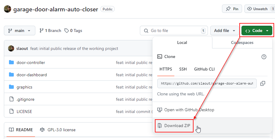
The source is available as an Open Source project on GitHub—feel free to contribute or explore alternate versions / forks...
Download the source files by clicking the "Code" button and then selecting "Download ZIP" in the popup menu.
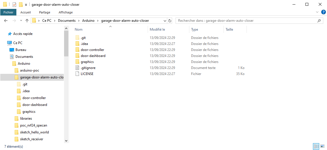
Extract the "garage-door-alarm-auto-closer" folder from the ZIP file and place it into your Documents/Arduino directory.
The project consists of two modules:
- door-controller: Code for the Arduino connected to the garage door.
- door-dashboard: Code for the Arduino in the living room, which monitors the garage door state and controls its closing.
Open these two projects in the Arduino IDE.
Both projects include a "src" folder containing code shared between the two modules. This could be turned into a standalone library if needed later. However, these files are purely technical and do not require modification when customizing the projects. Customization is primarily done through the source files at the root of each Arduino project.
Configure the Garage Door Controller Software (Garage-Side)
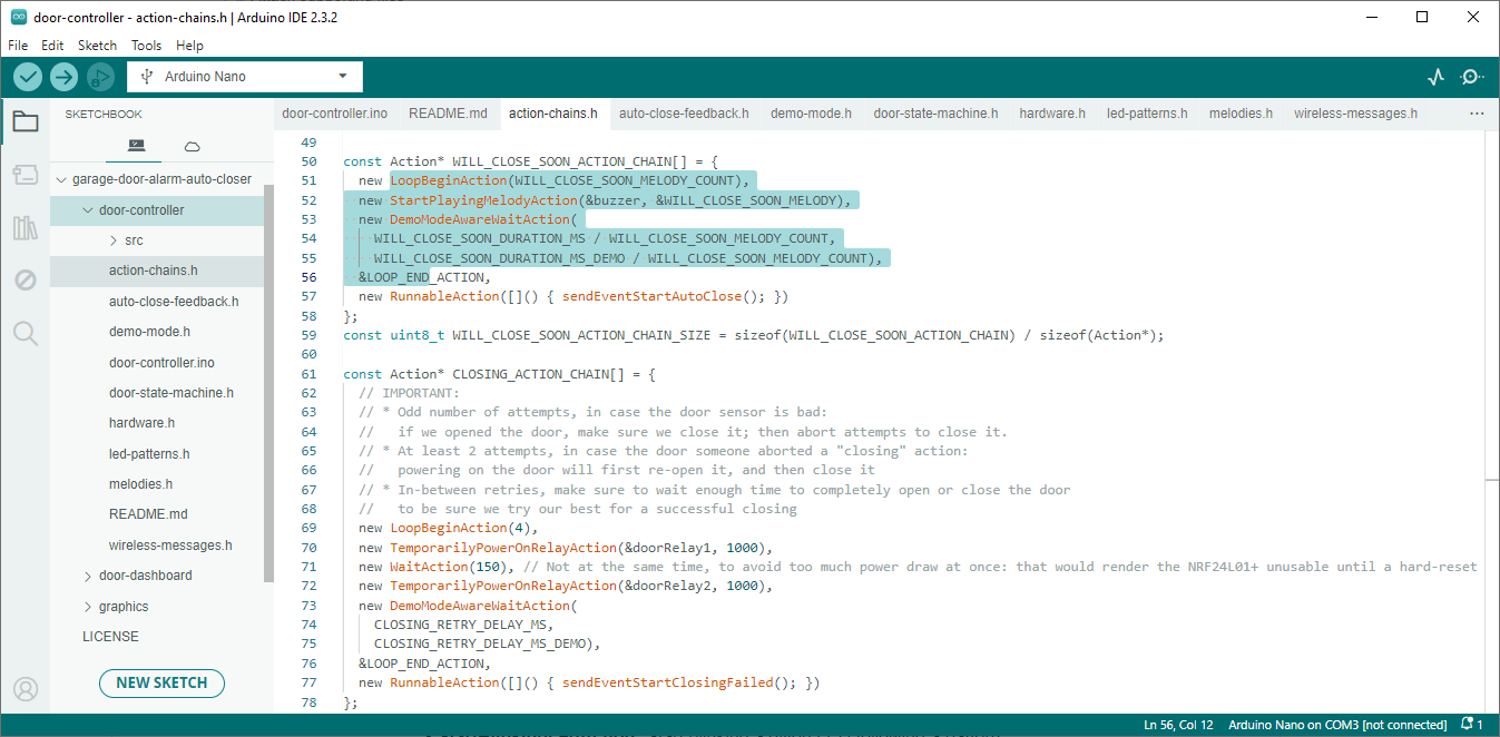
The project can be used as is.
Though I highly recommend tuning the CLOSING_RETRY_DELAY_MS constant depending on how long your garage door takes to open or close (see below).
However, the code of both Arduino modules can be configured to enable or adjust options.
On the controller side, you can mainly customize these files before uploading the project to the Arduino:
- action-chains.h:
- Adjust some timings:
- CLOSING_RETRY_DELAY_MS: The maximum time your door takes to close (or open). I timed mine at 20 seconds and added a 5-second margin.
- OPEN_DURATION_MS: The total duration before automatically closing the door.
- WILL_CLOSE_SOON_DURATION_MS: The time before auto-closing; this will trigger sounds on both Arduinos and blink the red LED.
- WILL_CLOSE_SOON_MELODY_COUNT: The number of audible warnings before the door automatically closes.
- You can configure behaviors for each state: lit or blinking LEDs, and melodies to play
- Each state (in which the controller can be) has an action chain—a declarative list of actions to execute sequentially when the states become active.
- To know which actions are available and how to use them, please see the documentation comments in the action-chain.h file.
- Basically:
- StartBlinkingLedAction: Start blinking a given LED following a pattern.
- StartAlternateBlinkingLedsAction: Start alternating blinking between two given LEDs.
- TurnOnLedAction: Turn on a given LED.
- TemporarilyPowerOnRelayAction: Power on a given relay for the specified duration.
- StartPlayingMelodyAction: Start playing the given melody on the buzzer.
- WaitAction: Wait for waitDuration milliseconds before running the next action.
- DemoModeAwareWaitAction (in demo-mode.h): Wait a long time in normal mode but a shorter time when demo mode is active.
- RunnableAction: Run a function.
- LoopBeginAction: Marks the beginning of a loop to run the next actions several times.
- LOOP_BEGIN_ACTION: Use it to start an infinite loop.
- LOOP_END_ACTION: Marks the end of a loop, to potentially re-run the previous actions several times.
- All actions are reverted when the state ends, and thus the action chain terminates.
- This is a declarative process (without explicit code) to ensure the responsiveness of the interfaces (reacting to all external events) and to avoid any synchronization bugs.
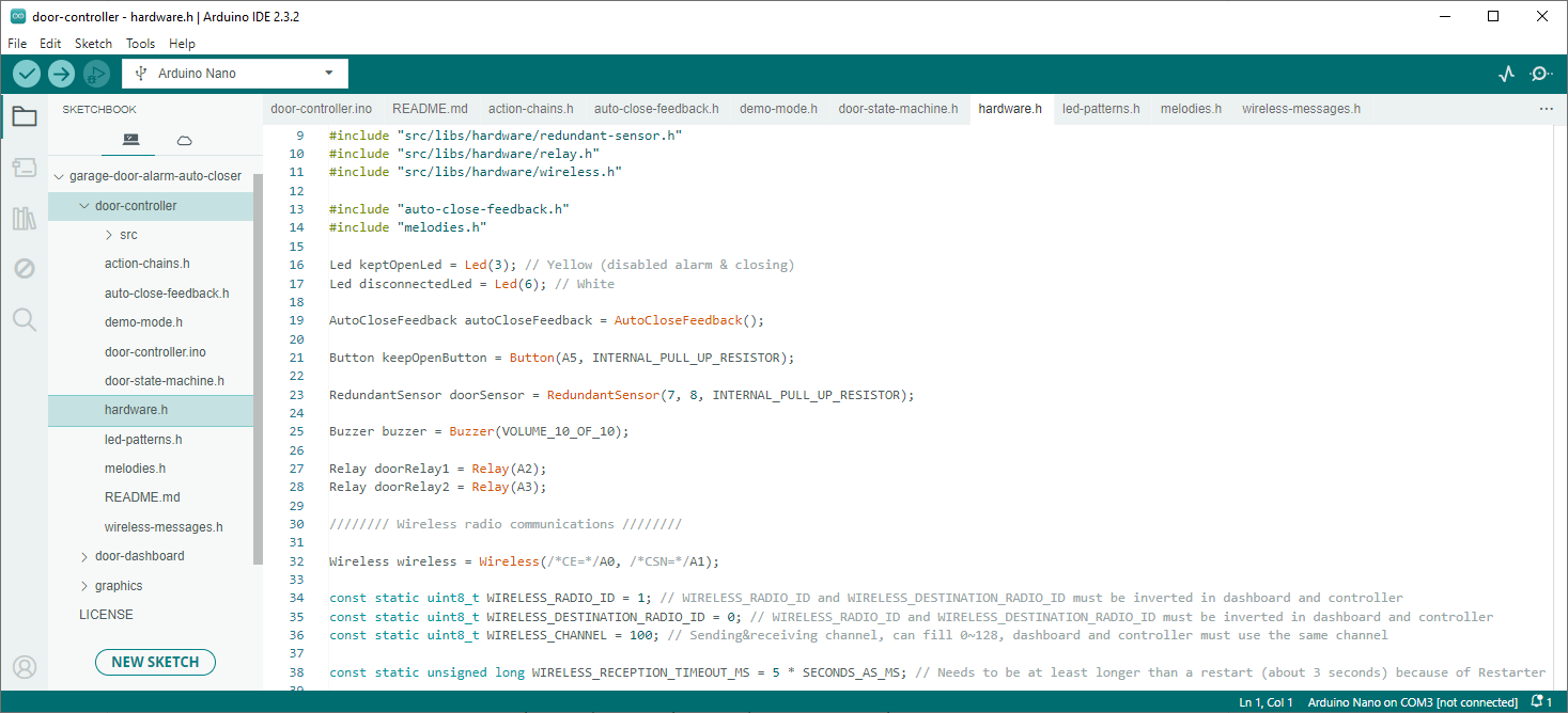
- hardware.h:
- You can configure all Arduino pins (if you changed some) and wireless configurations.
- led-patterns.h:
- You can configure how LEDs blink.
- (Only one pattern on the controller: DISCONNECTED_LED_PATTERN)
- melodies.h:
- You can configure melodies to play on the buzzer for each state or event.
- (Only one melody on the controller: WILL_CLOSE_SOON_MELODY)
Configure the Dashboard Software (House-Side)


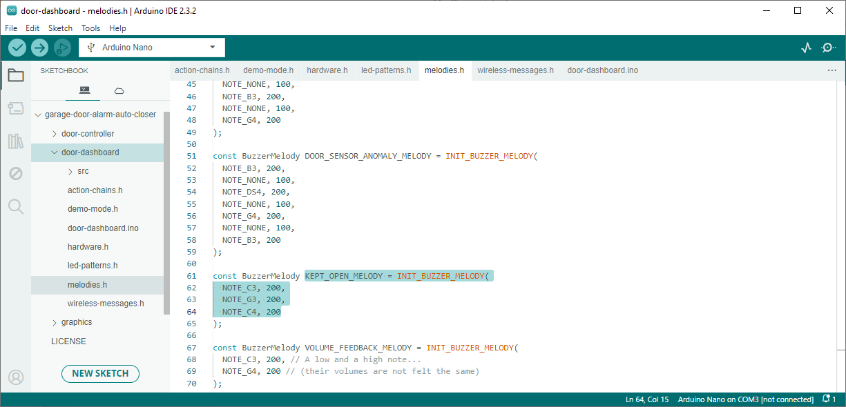
Likewise, there is nothing to adjust on the dashboard side, but you can still tweak these elements to your liking:
- action-chains.h:
- You can configure behaviors for each state (lit or blinking LEDs, and melodies to play).
- It offers much more interactivity than the controller, so feel free to fine-tune it as you like.
- It also handles button press combinations.
- Refer to the actions list mentioned in the previous chapter.
- hardware.h:
- You can configure all Arduino pins, wireless settings, and buzzer volume steps.
- led-patterns.h:
- You can configure how LEDs blink for each state.
- It includes many more patterns compared to the controller.
- melodies.h:
- You can configure melodies to play on the buzzer for each state or event.
- It also has more melodies than the controller.
Upload Modules Code
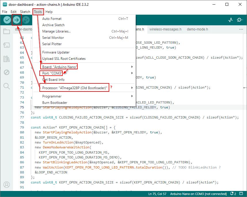
Open the dashboard project in Arduino IDE.
In the Tools menu:
- Select the board "Arduino Nano"
- Select the correct COM port (it will appear after plugging in your Arduino).
- OPTIONALLY, if you have an older version of the Arduino or a clone, select the processor "ATmega328P (Old Bootloader)".
Then, click the Upload button (the big arrow icon).
Open the controller project in another Arduino IDE window and do the same.
Note: You can connect both Arduinos simultaneously for debugging purposes if you modify the software—just select a different port for each.
Build the Photo-Frame Dashboard Module Casing


Download the attached English or French PDF below:
- The top graphic is the one to print on a transparent sheet.
- The bottom graphic includes crosses to guide where to drill the holes for the LEDs.
- The right circles should be printed on a thin white paper sheet to stick under the LED icons.
- You can download the SVG file used to create these PDFs to customize them to your frame or language.
Here are the steps to create the photo-frame:
- GIF 1: Invert the photo so it isn't inset in the frame, clearing space for the electronics.
- GIF 2: Print the graphics (available in English & French) on transparent sticker paper. If modifications are needed, the SVG file is provided and can be freely edited in Inkscape.
- Fold the sticker paper.
- Cut the sticker paper.
- GIF 3: On the outer frame, drill the 5 holes for the LEDs with a 10 mm drill bit, centered on the printed marked crosses.
- Protect the frame by placing a small piece of wood against it, to prevent splinters when drilling.
- Lightly sand the holes to clean them up.
- GIFs 4 & 5: On the inset, drill the 5 LED holes with a 10 mm drill bit, aligned with the previously drilled holes (BE CAREFUL: insert the glass before positioning the inset to avoid drilling misalignment).
- GIF 6: Glue the inset to the back wooden plaque of the frame with a hot-glue gun. Do NOT glue the top yet (where the 5 LED holes meet).
- GIF 7: Cut two wooden plaques to place beneath the inset:
- One to recess the LEDs slightly, allowing the inset frame to slide freely. Cut 5 holes with a 10 mm drill bit.
- One to support the LEDs. Cut 5 holes with a 3 mm drill bit, just large enough for the two LED pins to pass through.
- GIF 8: Glue the two wooden plaques inside the frame using a hot-glue gun. Apply glue on the left, right, and bottom of the plaques.
- IMAGE 9: The LEDs should be centered in their holes and should not protrude.
- GIF 10: Place a sheet of paper on top to check the LED brightness (after completing the circuit, if possible):
- Are the LEDs bright enough? Are they evenly bright?
- Use larger resistors to reduce brightness and smaller resistors to increase brightness.
- Use an ammeter to ensure current does not exceed 20 mA per LED (it is an Arduino Nano limit).
- IMAGE 11: Cut the sticker.
- IMAGE 12: Cut 10 mm circles out of very thin paper. (WARNING: In the video, I used tracing paper, but the icons weren't visible enough when not lit. I replaced it with a thin white sheet of paper for better results, while the resistors were bright enough to shine through.)
- GIF 13: WARNING: The ink on transparent sticker paper is prone to wear from slight scratches. I recommend applying a second transparent sheet on top to protect the drawings. Be patient and meticulous to avoid air bubbles.
- GIF 14: Remove the protective white backing from the sticker and stick the 5 white paper circles over the icons. (TIP: Keep protective plastic/paper on the left and right edges of the sticker to avoid leaving fingerprints on the sticky side.)
- GIF 15: Stick the sticker onto the top of the photo frame (remove the protective parts on the right and left at the very last moment). Fold the paper behind the frame. (I recommend printing the sticker larger and folding it inside the frame, securing it with tape if needed.)
- GIF 16: Now for the back of the frame: Measure the screw thread of the buttons (e.g., 15 mm) and drill a hole with a bit of that diameter. (WARNING: Ensure there’s enough space at the top of the frame to screw the button inside, while considering the wooden plaques added to recess the LEDs. If not, you may need to fix this mistake as I did in later videos. ;-) )
- GIF 17: Stick the second part of the sticker onto the back of the frame. (Remember to cover the sticker with another transparent sheet to protect the ink.)
- GIF 18: Cut holes and screw in the buttons (remove the middle LEDs to allow room for this). Pierce the center with a wood drill bit, then cut a star shape from the outside to the inside with a cutter. Use scissors to cut the triangles, then screw in the button (not shown in the video).
- GIT 19: Fasten the bolts on the buttons inside the frame. (Note how space at the top is constrained by the wooden plaques, so the buttons should be positioned below.)
- GIF 20: Measure the diameter of the speaker and the width of the USB plug. Drill corresponding holes at the bottom of the back of the frame.
- GIF 21: Insert the speaker and USB cable through the holes.
- IMAGE 22: Solder and place the electronics inside the frame (see the next step for details).
- GIF 23: Isolate circuits (using chater-tone tape) and secure them in the box with a hot-glue gun. This prevents accidental short circuits and keeps parts from moving when the frame is handled. Finally, close the frame!
Of course, you will place a personal photo in the frame :-) For the demo, I used this picture for credits.
Build the Photo-Frame Dashboard Module Electronics


It's time to heat up your soldering iron!
Follow the schematic...
An A4 page with high-resolution schematics of both modules can be downloaded below in the supporting file attached to this step.
Print that PDF to make soldering easier (for example, to check the wires you've already connected).
Downloads
Build the Door-Controller Module Electronics


n A4 page with high-resolution schematics of both modules can be downloaded above in the supporting file attached to the previous step.
Build and Plug the Door Sensor


The limit switches trigger the alarm as soon as the door is slightly open, ensuring maximum effectiveness. For example, we often ventilate our garage by opening it just a few centimeters. We then press the "Keep Open" button and still receive an alert at the end of the day to remind us to close the door before going to bed.
This sensor module is designed for easy maintenance: the screw terminal blocks allow you to unscrew the module and replace a failed relay without needing to solder in a tight space in your garage :-)
- Solder both "COM" pins to a common screw terminal block (with e.g., ground wires).
- Solder each "NC" (Normally Closed) pin to a separate screw terminal block (with live/brown or neutral/blue wires).
For security reasons, do NOT replace the wired connections with wireless equivalents. Always connect this sensor module directly to the controller module.
Plug in to the Door Motor


- Plug the two wires for the motor command.
- Luckily, there was an electrical plug for the motor: I added a small power strip and ran an extension cord from there. I secured the wires with electrical cable ties and plastic round cable clamps. You may be able to plug the Arduino into a different location along the sensor wires...
Mount the Door Controller Module


- Screw the controller box onto the wall.
- Screw the 5 wires into the screw terminal blocks (3 for the sensors + 2 to control the motor).
- Plug the USB power cable into the Arduino.
- The box is designed to be air-tight to prevent humidity from getting inside and to keep the electronics dry. I used hot glue to maintain this by sealing the following holes:
- The top wire hole
- The buzzer
- The LEDs
How to Get Reliable Wireless Communications
🔺 The Nrf24L01+ modules need a stable power supply, so be aware that you will get a better connection when:
- Solder all connections between the module and the Arduino. Dupont wires are too fragile (movement can cause the modules to lose connection).
- Some power modules do not provide a reliable connection: I soldered wires instead.
- Relays cause voltage fluctuations when triggered: a capacitor at their VCC and GND pins smooths this out.
- I also added capacitors in parallel at the VCC and GND pins of the module: 10 µF to smooth low-frequency noise (such as when buttons or relays are triggered) and 0.1 µF to smooth high-frequency noise (such as when the modules communicate via high-frequency radio waves).
- Some Chinese clones can freeze while waiting for ACKnowledgment packets to be received. I disabled ACK in this project, so no worries.
- You can also shield the modules with aluminum foil. I didn't need to do this, but it can help increase range.
✅ After implementing these changes, I went from very fragile connections (with Dupont wires) to a very solid connection that has worked perfectly for weeks with the Arduinos powered on.
💡 As an exercise for the reader, the Arduino Nano + Nrf24L01+ modules can be replaced with an Arduino Nano ESP32. This allows for custom 2.4GHz connections (without Bluetooth or WiFi) for simpler and more resilient communication using the ESP-NOW protocol (a very thin layer on top of Ethernet, see documentation).
Bonus: Making Of


Here are the development and testing boards :-)
And the first and second blueprints that initiated the state machine for easy development. These are not the final state diagrams.
A lot changed during development for better usability: LED colors were inverted, and naming was shifted away to focus solely on the door state (e.g. rename "Mute" to "Keep Open" because it was not indicating that muting the sound alarm would also prevent the door from automatically closing). Some LEDs had too many illogical blinking modes (for example, the green LED blinking to indicate the door was about to close, instead of blinking the red LED to emphasize that the door was still open). Initially, the dashboard was the "brain" of the system, rather than the controller (auto-closing would not have been reliable in the case of signal loss, and the code was more complex).
This reminds us that design is an iterative process that continually offers feedback on what to improve next!
I believe I arrived at a clear and user-friendly interface. It was easily adopted by my wife, which validates that assumption ;-)