Gas Leakage Detection Device From an Old Solar Lamp - Trash to Safety
by ROBO HUB in Circuits > Arduino
531 Views, 1 Favorites, 0 Comments
Gas Leakage Detection Device From an Old Solar Lamp - Trash to Safety
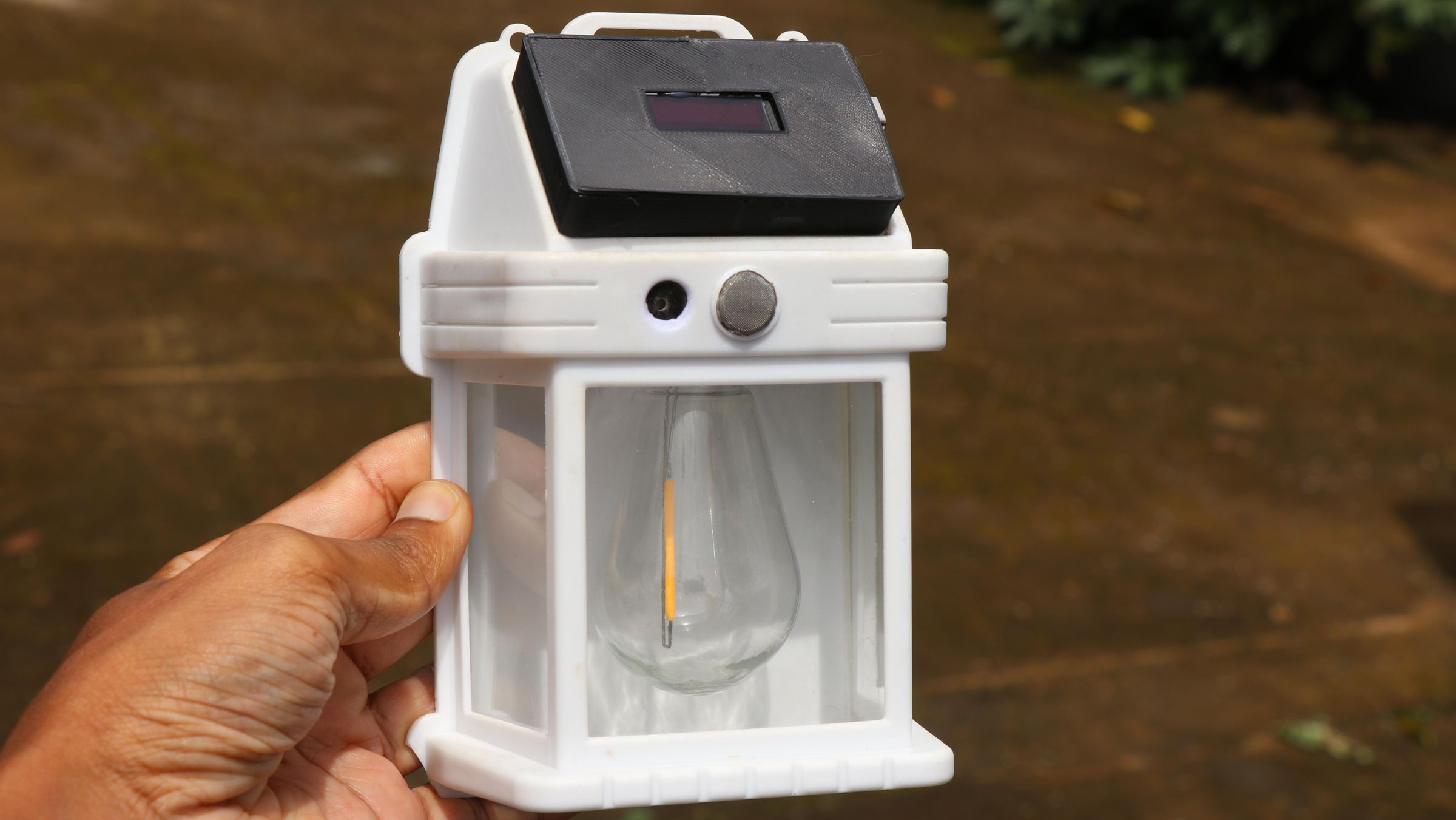
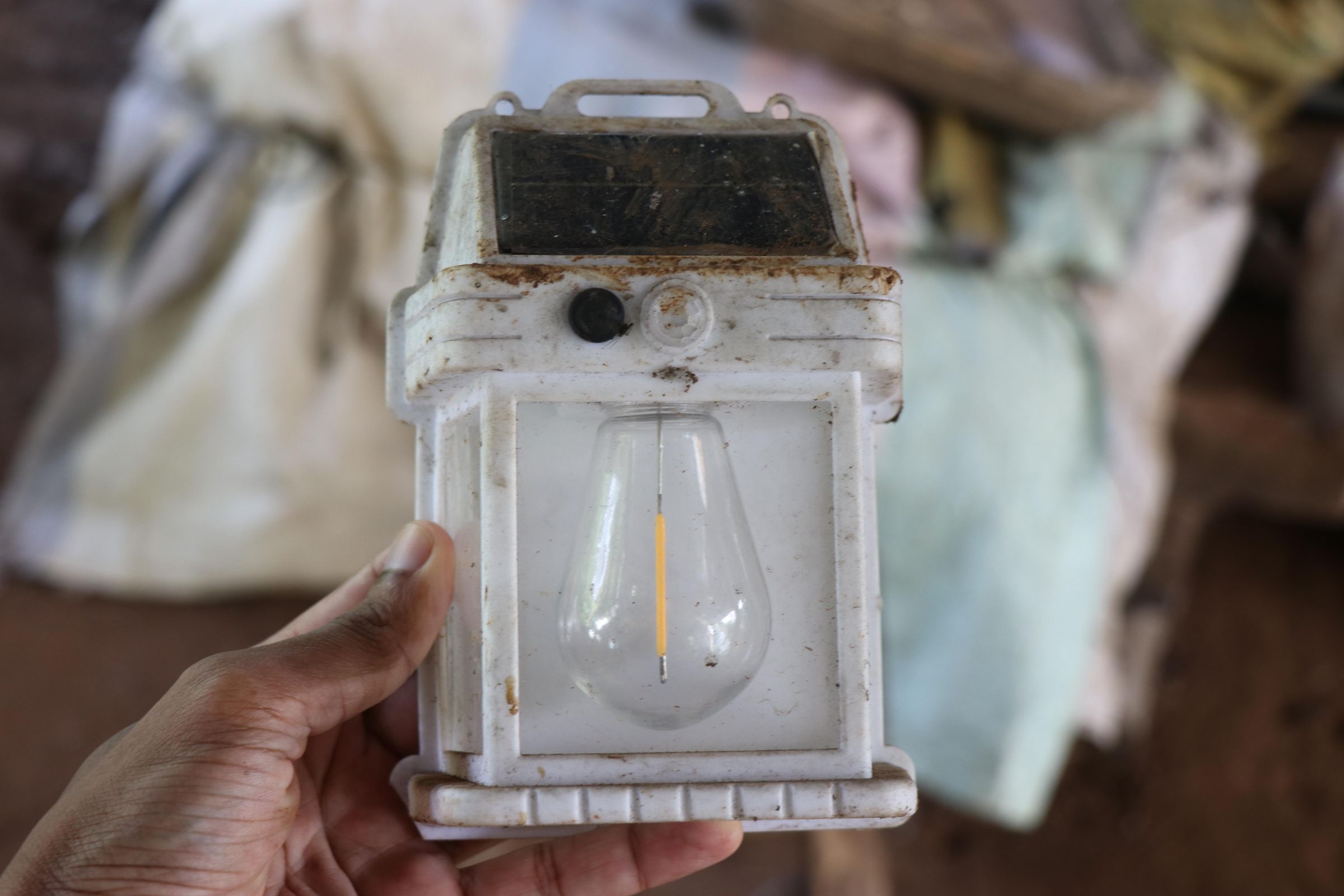
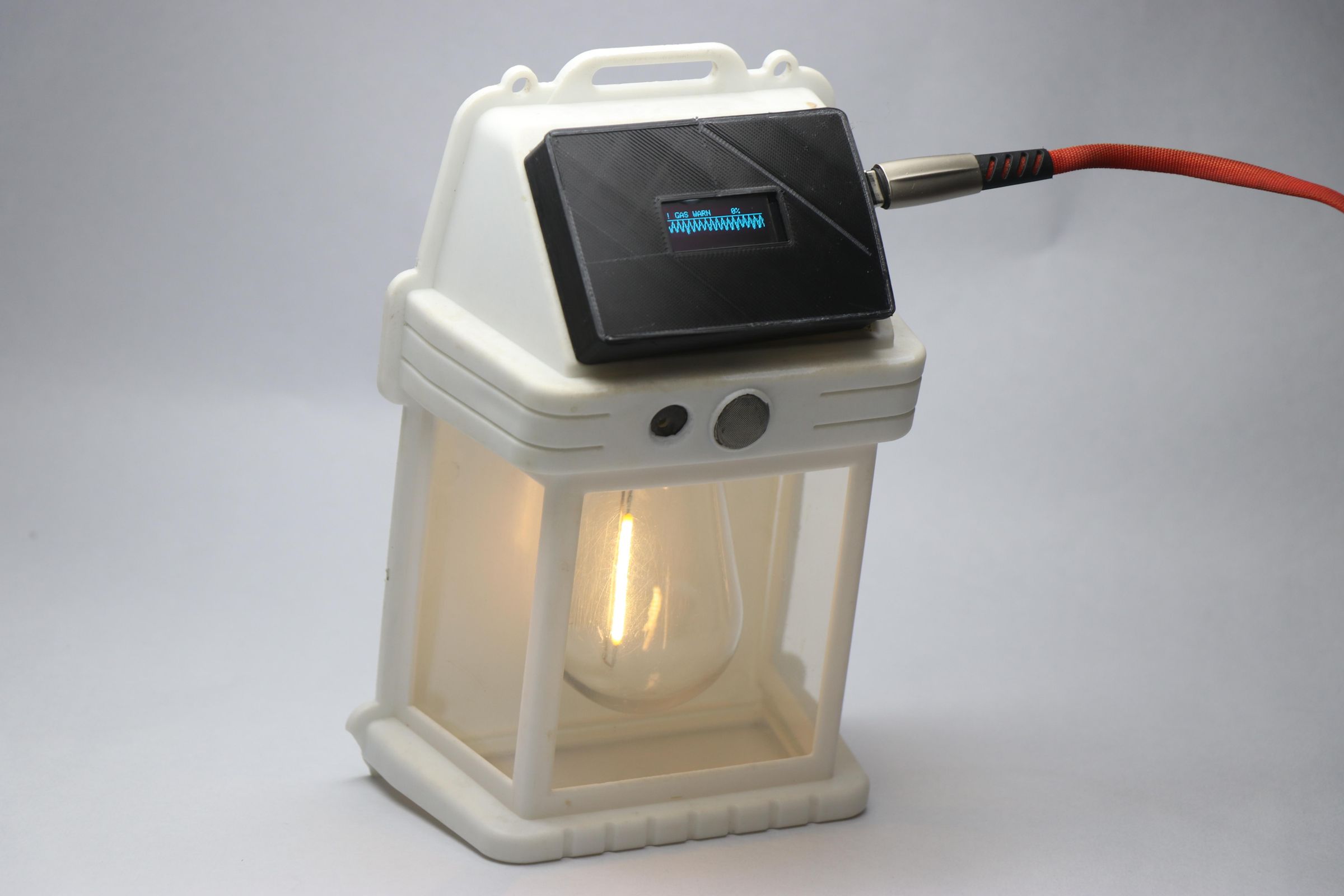
Hello people in this instructables i will show you how to convert this abandoned and non working solar lamp to gas leakage detection device.
This device not only detects gas leakages but also shows the realtime view on OLED and alerts through buzzer and edison led filament(upcycled from lamp itself)
Now you may ask why the need of light indicator and an onscreen OLED with realtime statuses?
Its because in case if any leakages from garage or any other place if a person is blessed with all senses they can be alerted by this device alert sounds.
Imagine a scenario where the person is unable to hear so they can take advantage of the edison led blink alter mathod or on the OLED, Here the buzzers doesnt seems to help!
Another scenario where it is dark and the gas leakage is happening now the person is unable to see the light from another place here in this case buzzer seems to be helpful.
Bonus scenario! if you catch cold you cant smell anything and here the alert system will be helpful!
There are many such instances where the features of this device seems to make sense so as a whole i added 3 types of indicators so this could fit in everyday circumstances.
If you are a camper and in a tent if there is any leakages while you are asleep this seems to be handy in alerting and helping you get out from situations.
The main reason behind this build is, I have been seeing this solar la,p which was in non working condition from a very long time.
I didnt know whether the inside components are working or not, But in almost cases the issue will be either with the battery or the circuit.
In my case and possibly in your case too this will be the same, solar panel and the edison led filament will seem to work fine.
Since the solar charging cycles will damage the circuit and the battery the other component has very less chances of being damaged.
Considering this i wanted to make use of the solar lamp body/frame since it is light in weight and can accomodate all the electronics.
Plastic waste are the major cause of soil pollution, by upcycling this was we can give it a second life for the device as well as for the person!
With this being said let us now know few things about this device.
Powered by esp32c3 super mini and OLED along with the gas sensor module this is a working gas leakage detection sensor that you can make at home.
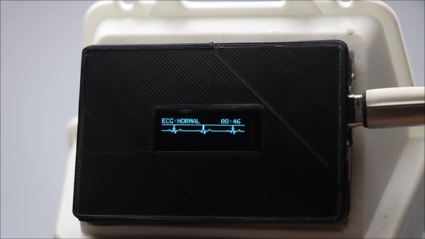
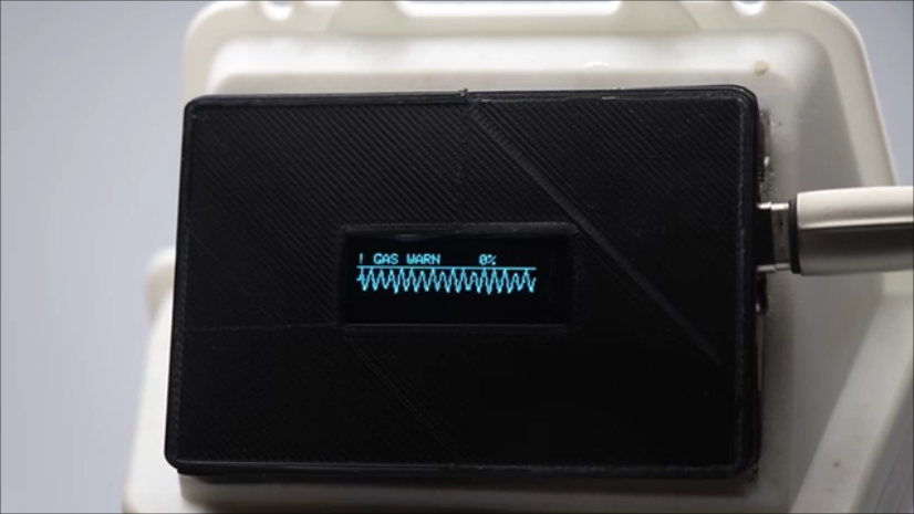
The edison led filament will give pulses of bright light when the gas sensor detects gas leakages and also the oled on standby gives straight lines and upon detecting gas it shows the graph like an ECG device alongside the buzzer beeping.
I did not want to add an battery and create a circuit that might carry the risk of igniting gas so i will be powering this device with USB power.
With this being told let us hop in to the building of this project.
Supplies
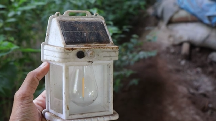
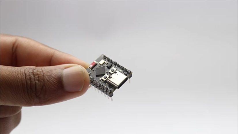
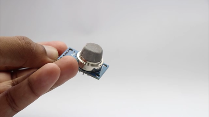
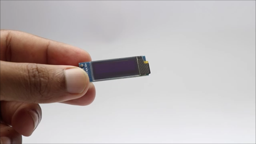
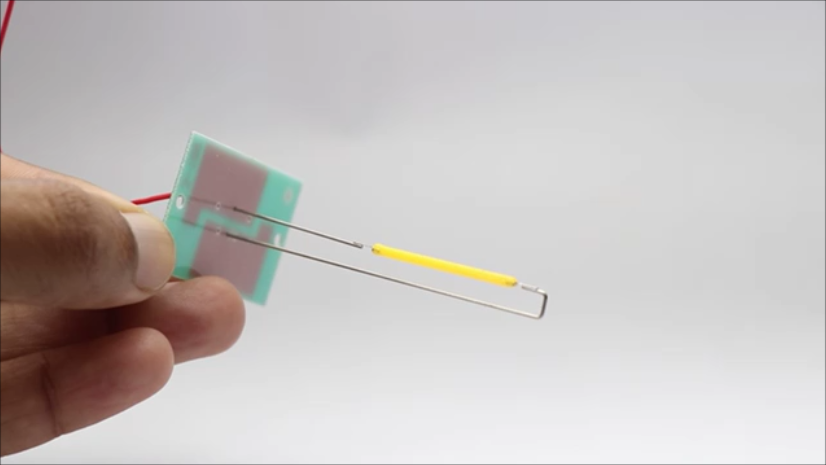
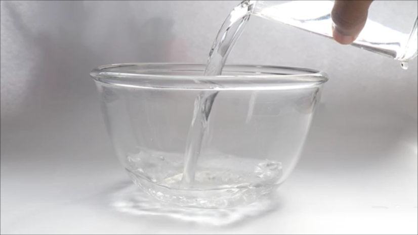
I will use the old solar powered lantern or the light and it needed clening so here is the complete list of materials to make this project
Old Solar Lamp (similar one here)
Gas Sensor(MQ2)
Bowl+Water+Cleaning Liquid+Brush
Jumper Cables
Breadboard(for circuit test-Optional)
Piezoelectric Buzzer(Small)
Hot Glue
Screw Driver(Star Type)
Ligher or nail polish liquid for testing
3D Printer
PLA Filament
Slicer(I used ultimaker cura)
Disassembling the Old Lamp
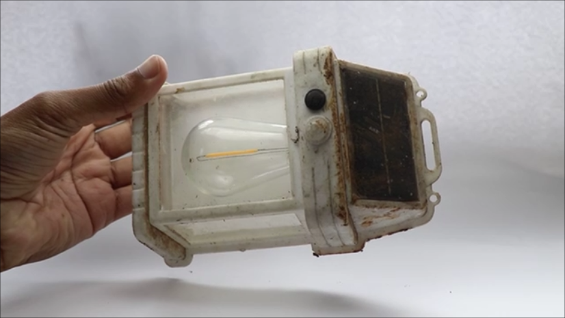
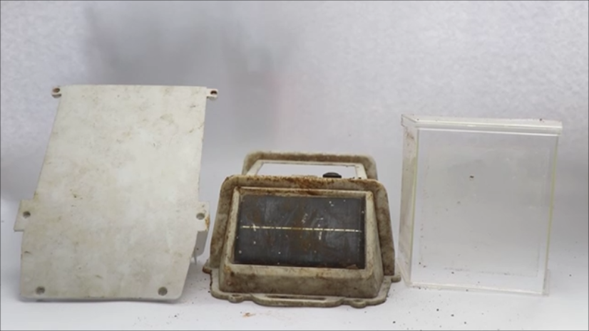
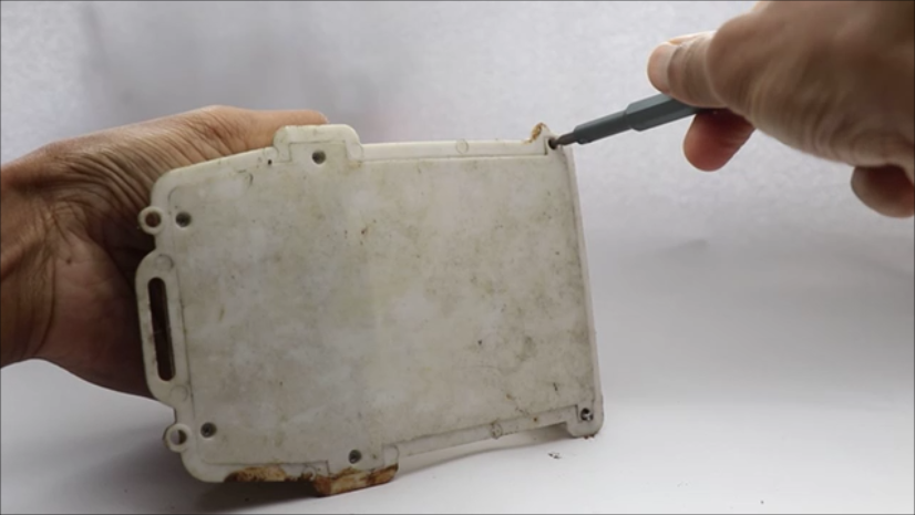
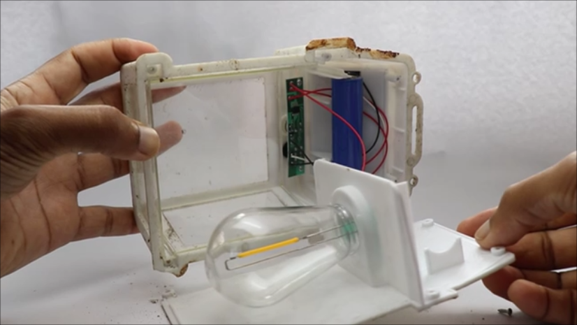
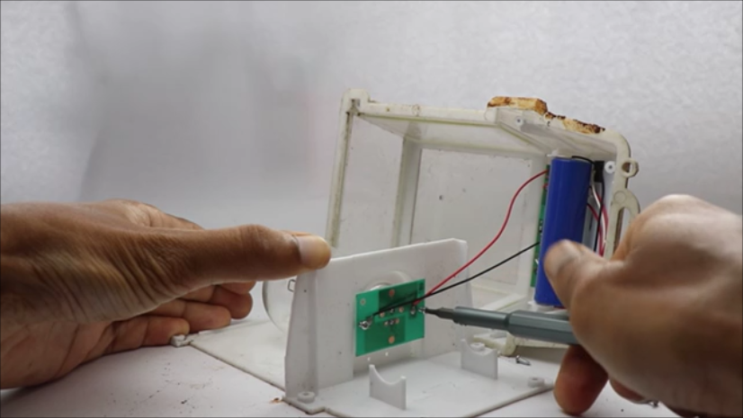
The lamp was abandoned since a long time and it was fully covered with dirt and marks and the best thing here you can do is clean it off.
I wanted all the parts to be clean so i will wipe of the dirt and spider webs! from the frame using a drying cloth first.
Later with the help of star type screw i will remove the back panel and remove all the electronics from inside.
I found that the battery was not useful and i had to dispose it, the solar panel still worked well and the electronics control circuit(small pcb) was of no use so i had to dispose that too.
Edison led filament was in great condition as expected, so saving these parts for later use i separated hardware from software.
The bulb did not need any cleaning and if needed wipe it gently with dry piece of cloth.
Now we have the parts and these needs to be cleaned first before they are put to use, So in the next step we will see how can you clean these hardware parts.
Cleaning the Parts

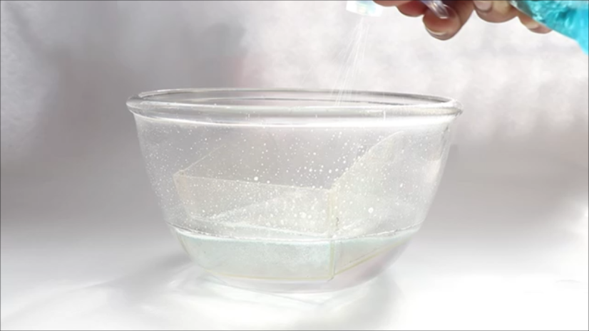
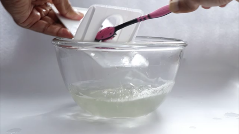
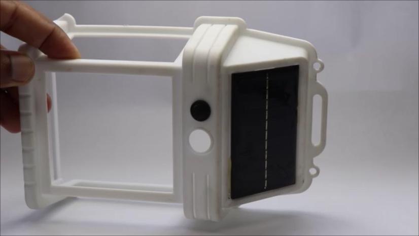
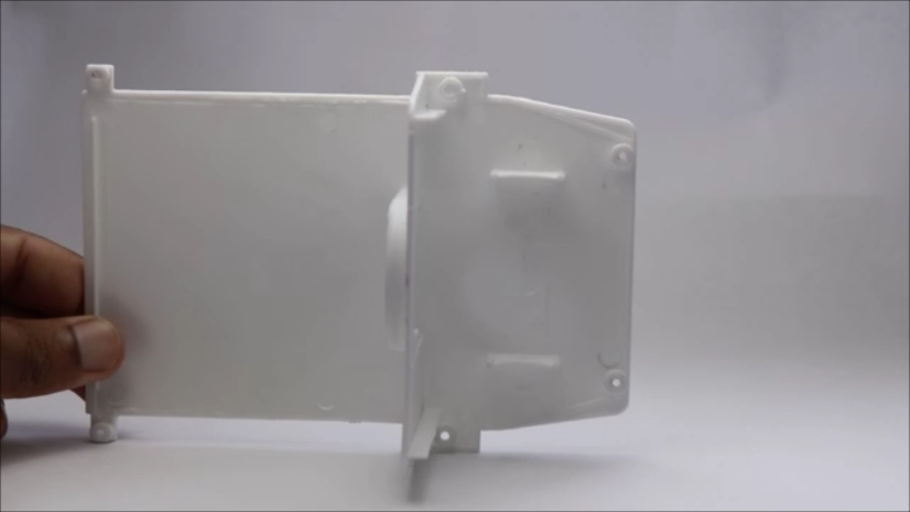
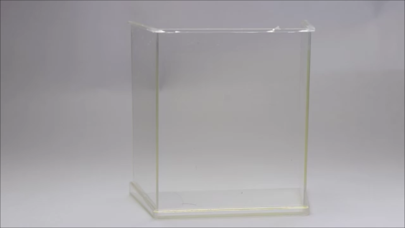
I will follow the most simple method to clean the parts covered with mud.
Take a bowl of water(fill to only 30%) and dip the plastic first, I then spreayed the glass cleaning liquid onto this and with the help of small brush started cleaning.
The plastic cover(looks like glass here) helps in seeing the indicator light(edison led filament) and should be cleaned gently to avoid any scratches.
Then i will proceed to clean the back lid of the lamp and these 2 parts will not take much time to get clean!
Now the most soiled(dirt) part was the front frame and it took me some time to clean this, i still used the same brush and cleaned the corners until i was able to see the original color of the lamp.
You can either remove the solar panel or clean it alongside other parts and this doesnt matter since the solar panel comes with waterproofed sealings.
It took me almost 20mins to get the clean parts, and after it is washed well i used a small piece to tap and dry the wet parts.
So overall this will not take more than 25mins, and you will get a perfect ready frame for this project.
Hardware is complete and now we will build the software part that gives life to this hardware and stay tuned for this on the next step.
Circuit and Program
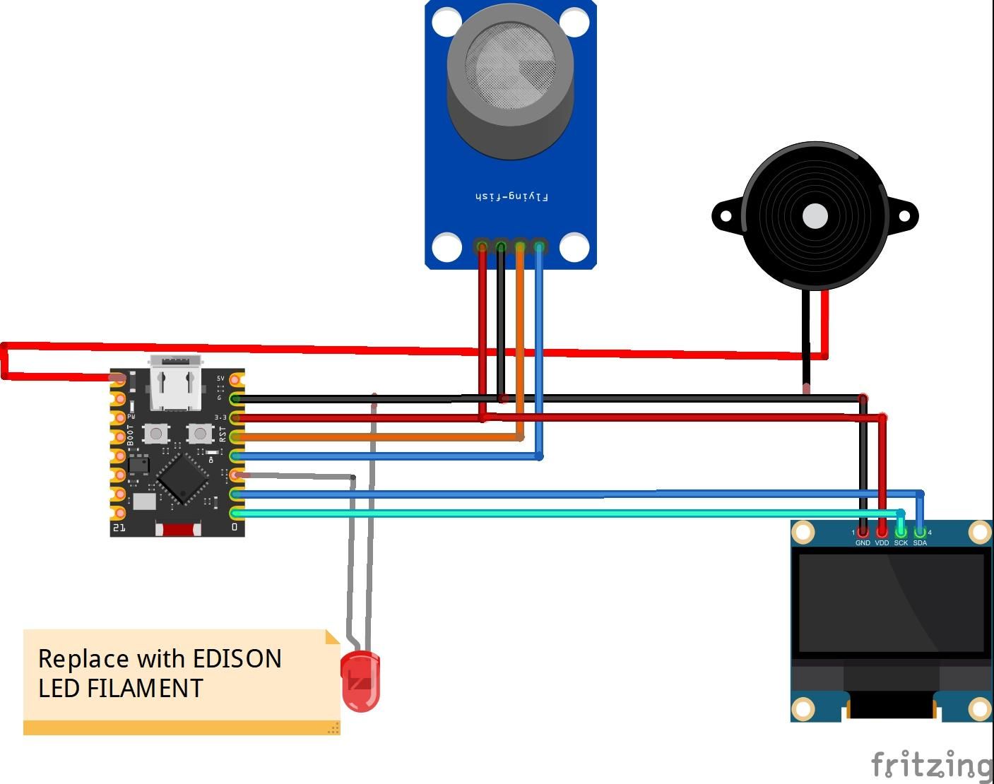
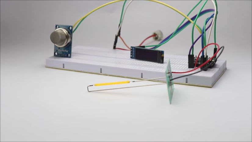



Here in this project we are using four components in total and i will break the circuit according to the components.
To begin with the gas sensor module
It has 4 pins and here the positive and gnd will be connected to 3v and the gnd pins on the esp32 board.
A0 pin is connected pin 3 to and the D0 pin is connected to pin 4 on esp32 board
OLED module connections
Vcc and gnd to the 3v and the ground pins whereas the Sda to pin 1 and the Scl to pin 0 on the esp32 board
Edison LED filament connections
Positive side of the pin is connected to pin 2 and the negative is connected to the ground.
Buzzer Connections
Ground is connected to gnd on the board whereas the positive side here is connected to pin 5 on the controller
After you make these connections connect the board to computer using the type c cable and then open arduino ide.
Use the below program inside your arduino ide and select proper board type and com port and click on upload.
If you have any issues with the upload update the latest library and you are good to go.
Not happy with this wire circuit?
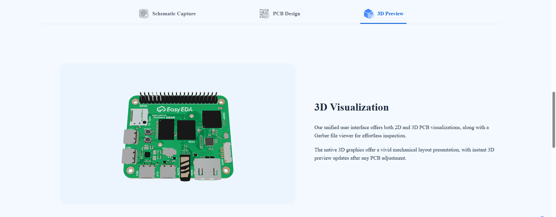
Get a custom PCB from JLCPCB they have PCB services for any type of projects, Use their EasyEDA tool to design PCB.
Im satisfied with their services and also they offer fast shipping, First time user ? Visit them to avail great coupons and offers.
Downloads
Simplifying the Circuit
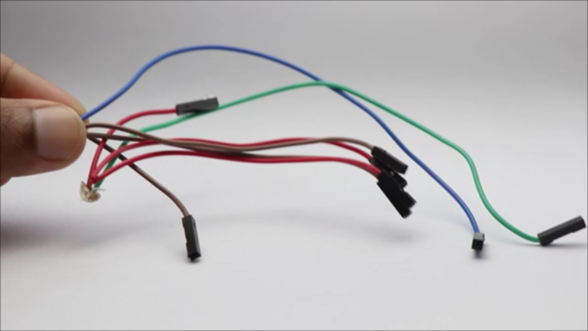
When i say the word simplifying it means that the breadboard prototype we just saw it is difficult to practially fit that circuit inside out solar lamp.
I later then figured out that reducing the number of wires also can shrink the size of circuit.
Here i mean that there are 4 components in total and all 4 needs to be connected to ground power pins and without the shrinking circuit if we are heading over to proceed with the general circuit we will end up with 4 wires for gnd.
But with simplification we are using one single gnd to multiple gnd and this modification is shown in second image on this step.
I have made 2 sets of these so that we can sort the negative with 4 common pins and 2 for positive power supply.
After this is done connect the components as mentioned in the circuit diagram and now you can again connect the esp32 board to usb power supply and check if everything works.
I again tested the sensor part for its working, ensuring everything works before assembling the electronics inside hardware will ensure that there are no issues later.
Assembling the Electronics
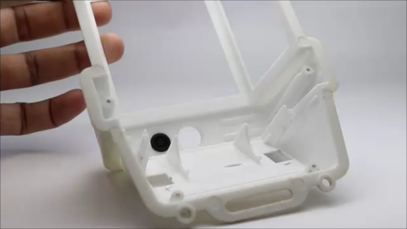
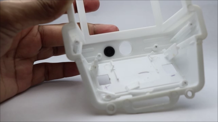

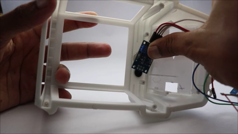
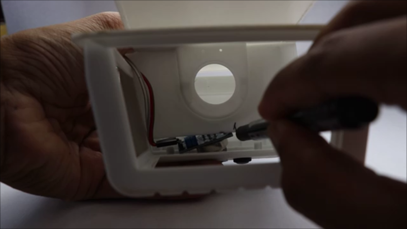
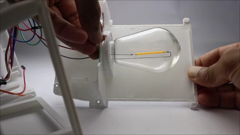
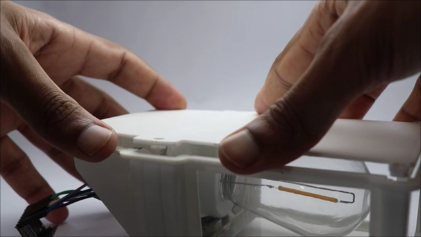
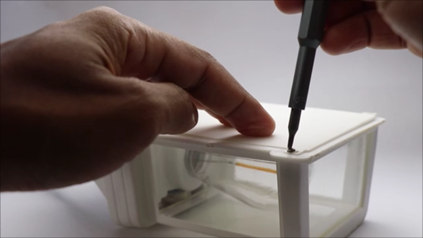
I will start by making the space inside the lamp frame, there were few extrusion kind of parts that were used in holding the battery when the lamp was working.
Now this is no longer required and i will trim it off with a cutter, now after i removed these extra parts we have enough room to fit in all the electronics.
I will then place the gas sensor first and i had to remove some parts from the lid part too, i did a marking and you can see the same too.
Now after this is done glue the gas sensor first and then the buzzer.
The Edison led filament will go inside the bulb as it was in the beginning, now use double sided adhesive or the hot glue wherever necessary.
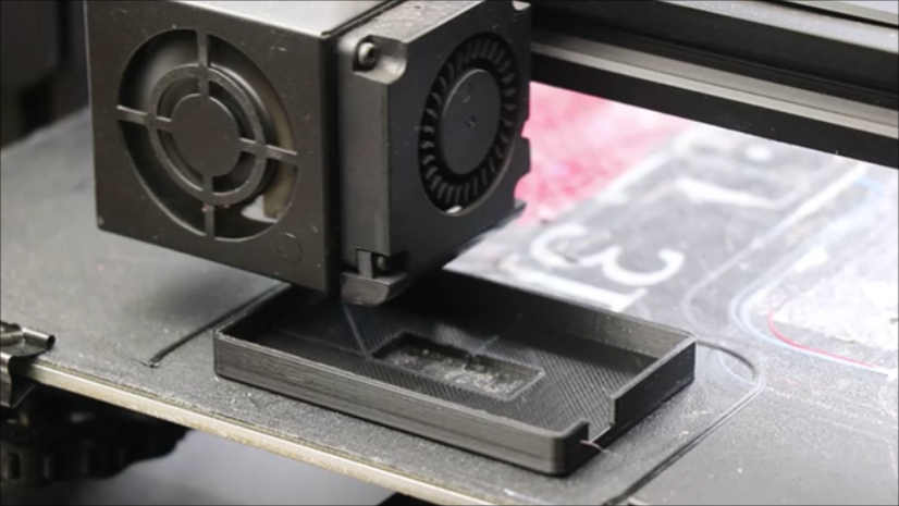
For the OLED holder i made a 3d printed enclosure that also holds the esp32 c3 board.
Use superglue to connect this 3d printed part with the lamp frame, and now with the help of screws you can fix the back lid once everything is kept on its place.
At this point we are almost done with the building part and only thing left now is the testing and using and we will see that in the next step.
How to Use This and a Video Tutorial of Complete Build and Testing
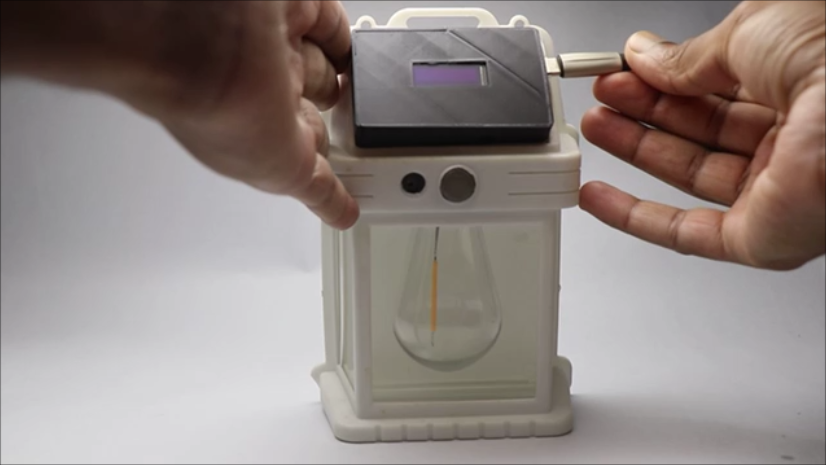
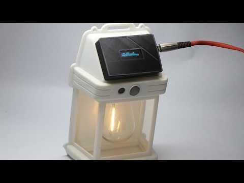
Using this is very simple, I will use power supply from the power bank connected to usb type C cable.
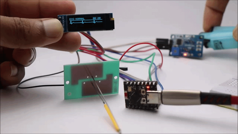
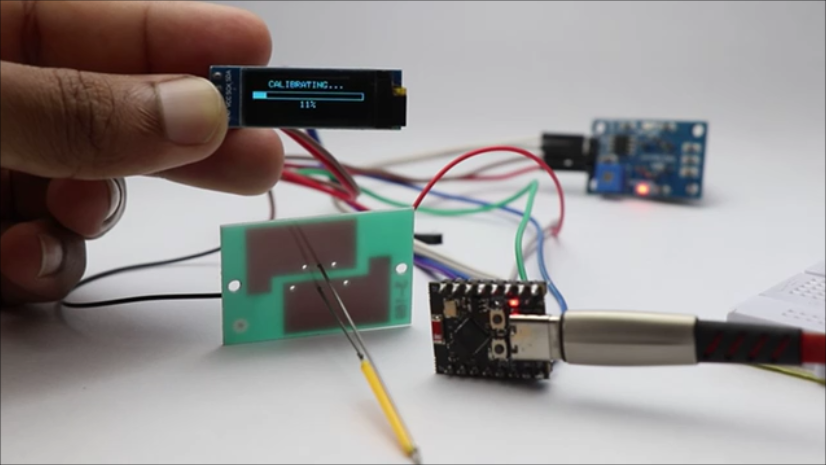
When you connect the pin to esp32 board the OLED shows the time since it was on in seconds, and the calibration happens and the sensors will be ready in few seconds.
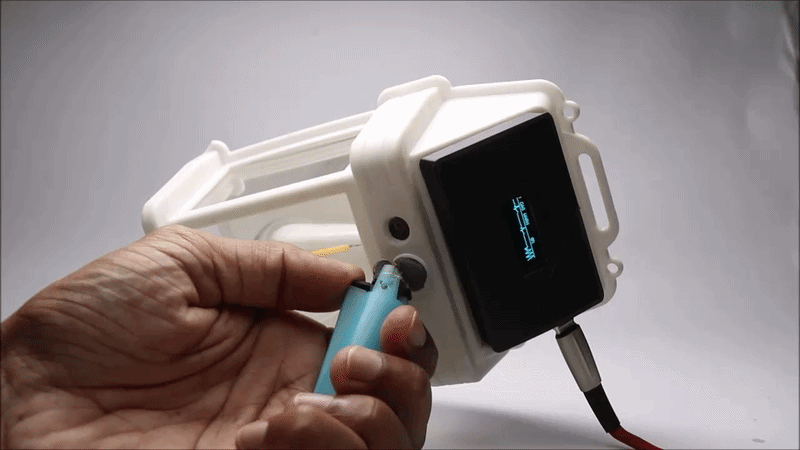
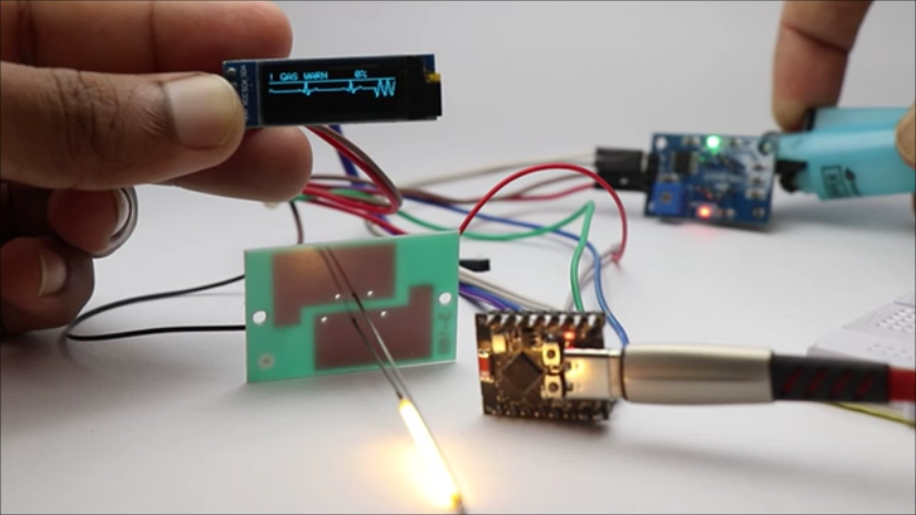
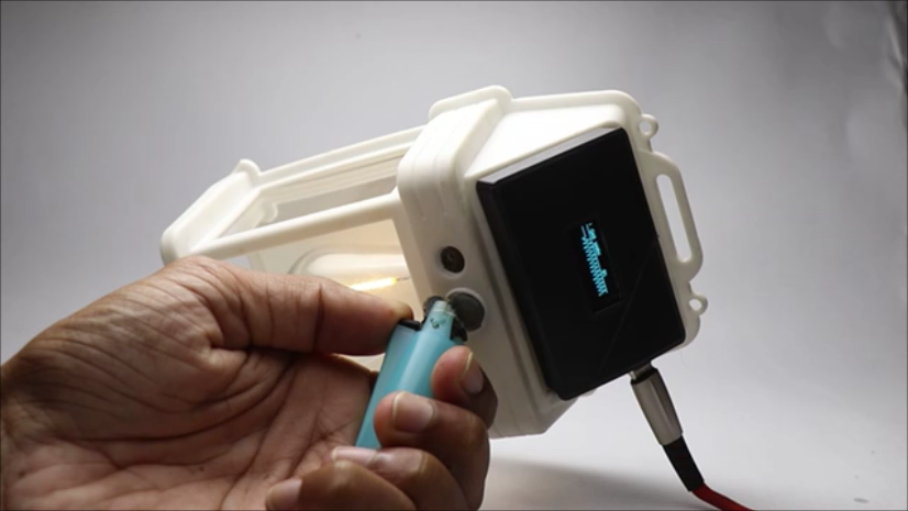
Here when the oled shows a straight line it means that the gas sensor is not sensing any leakage of gas, and if it detects any gas the oled shows curved lines!
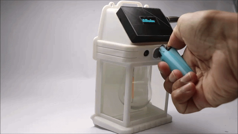
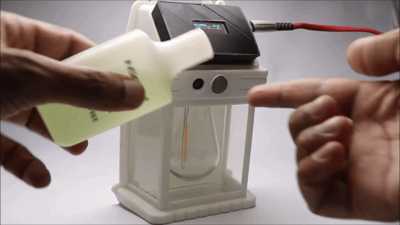
I tried exposing the sensor to gas from a small lighter and also the vapors from nail polish remover.
The gas sensor picks up and senses the gas and immediately the OLED shows curved lines and the buzzer beeps along with flashes of light from the edison led filament.
This was we have 3 ways to know that the leakage is happening.
I hope you will build this project and share the results of your build! you can post it in the i made it section if you are new here.
Dont miss to check this video that has the complete build of this project along with a working video.
I tested this device in many trials and found the results were pretty much good.
This was all about this project, any questions let me know in the comments, Have a great day!