Gear Indicator for Automotive Applications- Programming and Prototyping
by Carlos_Almeida in Circuits > Arduino
6989 Views, 15 Favorites, 0 Comments
Gear Indicator for Automotive Applications- Programming and Prototyping

Hi everyone, In this instructable I´m going to show you how I made a gear indicator for my car using an arduino uno , some sensors and a 7segment display.
The sensors I used were hall effect sensors, more on that in step 1.
In step 2 you will find and explanation on how to make numbers appear in the 7 segment display.
In step 3 I explain the code used and to finish there´s a video showing the project in a breadboard and some work I´ll be doing to implement this in my car (Uni is just around the corner and I wont look at this for some time).
Let´s get started :)
First of all, the list of components:
1x Arduino Uno
1x 7segment Display (Kingbright SC52-11GWA)
4x TLE4935L Bipolar Hall IC Switches
8x 4.7nF capacitors
4x 1.2kOhm resistors
8x 22Ohm resistors
8x 120Ohm resistors
Some jumper wires
Step 1: the Hall Effect Sensors


So, first of all, what is a hall effect sensor?
The hall effect is a physical phenomena that can be used to sense magnetic fields
The youtube channel SixtySymbols has good explanation on this phenomena
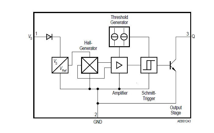
In this case, the sensor does not give you a measure of the magnetic field. It uses a schmitt trigger in order to put the output high or low accordingly to the magnetic field.
The sensor I used is bipolar, this means that sensor is sensitive to positive and negative values of magnetic field.
The conditioning circuit used is really simple, just a pull up resistor and two capacitors as you can see in the picture.
Vs and GND are for supplying energy and VQ is the output of the sensor.
For supply voltage and other information I leave you with the datasheet(PDF).
I supplied the sensors with 5V since that´s the voltage that the arduino uno runs on.
The problem I had with this sensors was that they latch. By that I mean that when you activate them the output stays in the high value even after the magnet moves away, to get around this issue I used code,more on that later.
Step 2: 7 Segment Display


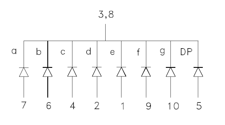
A 7 segment display is pretty much just a bunch of leds together and depending on which led you activate a different segment pops up.
There are two different types : common cathode (common ground) and common anode (common supply), in my case I used a common cathode display, the datasheet for it is the pdf you find in this step.
Whenever you find yourself working with leds, there´s always a need to use current limiting resistors or you´ll burn the leds.
The math behind the value of the resistor is quite easy.
The first thing you need to do is to find the foward voltage in the datasheet. The foward voltage is the voltage drop when the led is on. In my case there's two values, the typical (2.2V) and the max value (2.5V).
The second thing you need to find is the current the led requires in order to light up, in my case it was 25mA.
After looking up this information the math behind it is easy, the equation is:
R=(Vs-Vled)/Iled
Where:
Vs is the supply voltage
Vled is the foward voltage
iled is the curent
Since Vs is 5V, Vled is 2.2V and Iled is 25mA the resistor value is 112Ohm.
For good measure I used 120Ohm and 22Ohm resistors in series in order to get 140Ohms of resistance.
I made a schematic in EagleCAD where a jumper connected to the arduino uno supplies the module through the current limiting resistors.
Downloads
Step 3: the Code for the Arduino
In this step you´re going to find the code I used, its pretty much understandable if you have some knowledge about arduino code and interrupts, if not, don´t worry.
I used the library timer one just to save time, this library may be found here.
This code can still be optimized (a lllllllllllllllllloooot more).
The delayMicroseconds(70) line in the interrupt is there in order to give the input voltage of the sensors some time to rise (I eyeballed it).
The input voltage of the sensors is controlled because of the problem stated in step 1.
A video of the project can be seen here (that breadboard has been trough alot :D).
Downloads
Step 4 : Future Work


The future work will be focused on the mechanical side of things instead of electronics, I need to make a rack that connects to the lever in order to secure the magnet and the circuit for the sensors and it´s enclosure.
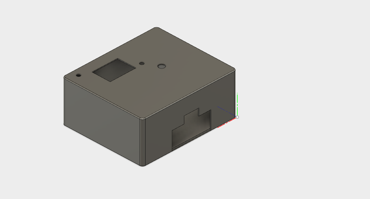
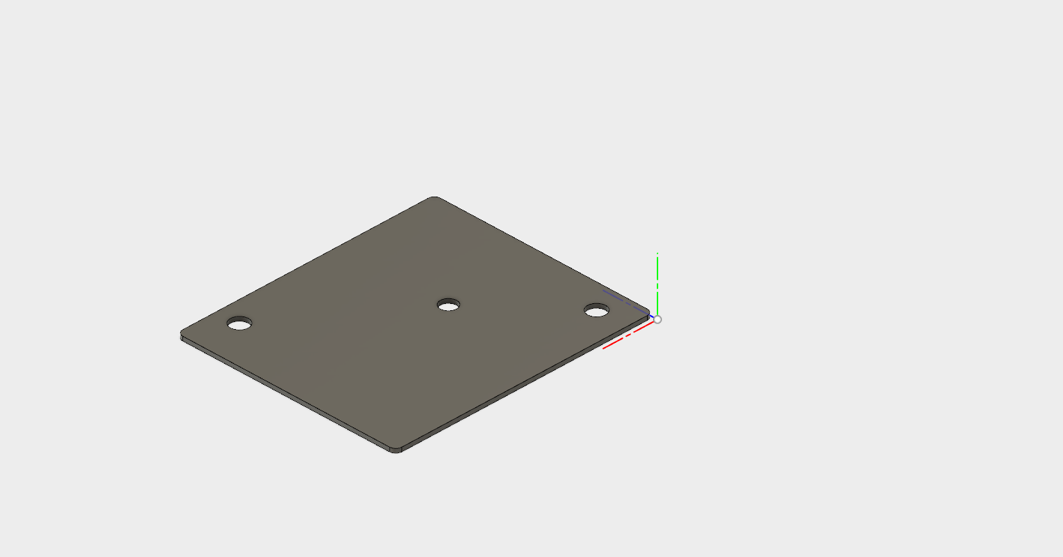
The only enclosure I´ve already done is for the 7 segment display, you can see the drawing from Fusion 360 in the pdf file and the images show both plates of the enclosure, also in Fusion360.
Any doubt or advice you have please feel free to contact me.
More projects involving my peugeot 106 coming soon :-)