GlowOnTheGo : LED Matrix Bag
by randomrofi in Circuits > Wearables
1661 Views, 18 Favorites, 0 Comments
GlowOnTheGo : LED Matrix Bag


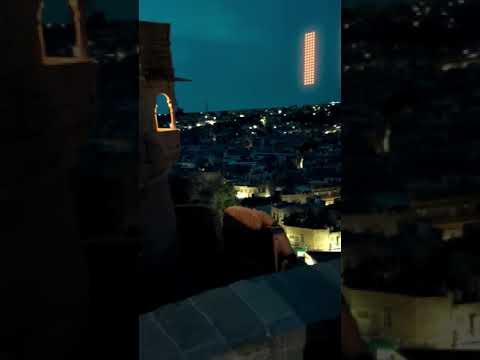
While casually browsing YouTube shorts, I stumbled upon a video showcasing a company selling a bag with an impressive RGB matrix display built in. However, the price tag of over 200 USD rendered it unaffordable for many. Inspired by the idea, I decided to embark on a DIY journey and create my own version, opting for a more budget-friendly approach.
By using a simple Red LED matrix and an ESP8266 microcontroller, I successfully developed a captivating LED display that can be controlled via my smartphone. The 3D-printed casing added a touch of personalization, making it a unique accessory for my backpack.
With a mobile app, programmed using Flutter, I now have complete control over the messages displayed on my LED matrix. I can experiment with various in and out animations, adjust the speed, and even pause the messages at strategic moments. Saving my favorite messages on the app allows for quick access, ensuring I can display them with just a single tap.
Not only did this DIY project provide a fun and engaging experience, but it also granted me the joy of self-expression. Whether it's a motivational quote or a witty remark, my backpack now becomes a canvas to share my thoughts and emotions with the world. And all of this was achieved with a mere 10-dollar investment and just two days of effort.
This is for the RED colour category in rainbow contest.
Supplies


Tools
- 3D printer Ender 3 V2 Neo Amazon USA / Amazon India
- screwdriver Amazon USA / Amazon India
- soldering iron Amazon USA / Amazon India
- soldering wire Amazon USA / Amazon India
Materials
- 3D filament Amazon USA / Amazon India
- wires Amazon USA / Amazon India
- Wemos Esp8266 D1 Mini Amazon USA / Amazon India
- female to female jumper wires Amazon USA / Amazon India
- LM7805 Amazon USA / Amazon India
- Capacitor 104 Amazon USA / Amazon India
- Diode 1N4007 Amazon USA / Amazon India
- Perfboard Amazon USA / Amazon India
- Male header pins Amazon USA / Amazon India
- Dot Matrix MAX7219 Amazon USA / Amazon India
- Screws * 4 Amazon USA / Amazon India
3D Design and 3D Printing


I have successfully designed a comprehensive cover for my project using Fusion 360. The cover consists of five distinct parts, each serving a specific purpose:
- Main Dot Matrix Cover: This part acts as the main enclosure for the Dot Matrix display, providing protection and support for the display unit.
- Top Cover (Cover Part 2): Designed to diffuse the light emitted by the display, the top cover also serves as a protective layer against external elements that could potentially affect the display's performance.
- Bottom Cover (Cover Part 3): The bottom cover is intended to protect the internal circuitry of the Dot Matrix, ensuring its longevity and reliability.
Together, these three parts form the top section of the display. The top section features four holes that allow for nuts and bolts to securely fasten the components, creating a robust and durable exterior.
- Holder/Cover (ESP Cover Pt.1): This component is specifically designed to house and secure the ESP8266 D1 mini circuit. It provides a safe and stable environment for the D1 mini.
- Bottom Cover (ESP Cover Pt.2): Serving as the bottom part of the D1 mini holder, this cover offers additional protection to the circuitry. The cover also includes several output ports to enable power supply options via USB or jumper wires connected to a battery.
With this well-designed assembly in Fusion 360, my project now has a complete and functional cover solution that ensures the safety and optimal performance of the Dot Matrix and ESP8266 D1 mini components. I'm looking forward to further testing and, if needed, prototyping to ensure the design meets all the desired requirements.
Assembling Dot Matrix Display Cover


Assembling the outer part of your project requires careful handling and attention to detail. Here are the steps to follow:
- Desoldering and Soldering Headers:
- Carefully desolder the old 90-degree male headers from the dot matrix display. Use a soldering iron and desoldering wick to remove the solder.
- Replace the 90-degree male headers with straight male headers that will fit better in your 3D print.
- Fitting the Dot Matrix Module:
- Place the modified dot matrix module into the designated space on the main part of the 3D print.
- Ensure that it fits perfectly. If it doesn't fit, you may need to use a knife to remove any extra plastic from the print or sand it down gently until the dot matrix fits properly.
- Attaching the Top Cover:
- Take the white top cover part and place it on the non-hole side of the main part (the side without the nuts and bolts holes).
- Apply superglue or a suitable adhesive to securely fix the top cover in place. Allow it to dry according to the manufacturer's instructions.
- Reassembling the Dot Matrix:
- Carefully place the dot matrix back into its position from the back of the assembly.
- Then, put the third part (bottom cover for the dot matrix) into place and check the fit of all the parts together.
- Adjustments:
- Check if all the parts fit together properly. If there are any alignment issues or parts don't fit well, make necessary adjustments.
- Use a knife or sandpaper to carefully fine-tune the fit, ensuring all the components sit securely and neatly.
After completing these steps, you should have the outer part of your project assembled and ready to be attached to the outer side of your bag. Make sure to verify that all the components are securely in place and that the dot matrix is functioning correctly before proceeding with the final attachment to your bag.
Making Circuit


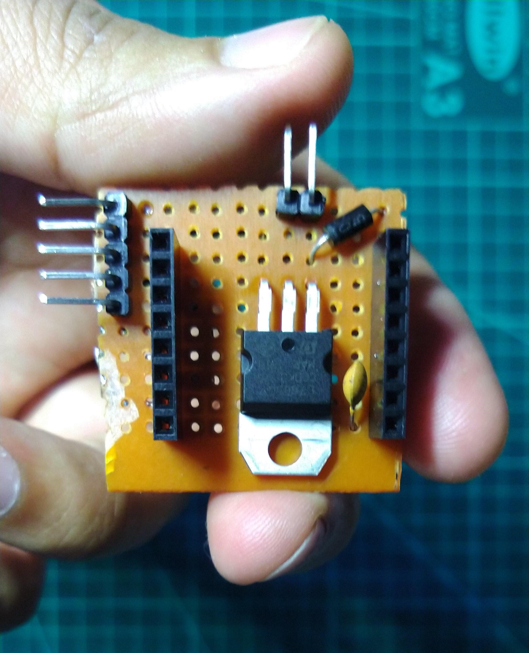
To create the circuit on a perfboard based on the design provided and to match the size of the 3D printed part (espcoverpt1), you can follow these steps:
- Gather Components: Gather all the electronic components required for the circuit based on the design. This will include the ESP8266 D1 mini, 7805, capacitors, and any other components needed to power and interface with the dot matrix.
- Plan the Circuit: Lay out the components on the perfboard in a way that matches the circuit design you have created. Plan the placement of each component to ensure a compact and neat arrangement.
- Solder Components: Begin soldering the components onto the perfboard. Start with the lowest-profile components first, like resistors and capacitors, and work your way up to larger components like the D1 mini.
- Wire Connections: Use small wires to create connections between the components as per the circuit design. Keep the wiring tidy and organized to avoid any potential shorts or issues.
- Check for Errors: Double-check your connections and solder joints to ensure there are no solder bridges or open circuits. Verify that the circuit matches your design correctly.
- Test the Circuit: Before proceeding to the next step, test the circuit to ensure that it functions as intended. Check that the dot matrix responds to the D1 mini and that all the output ports are working as expected.
- Size Adjustment: Once the circuit is verified and functional, compare the size of the perfboard circuit to the 3D printed part (espcoverpt1). If the perfboard is larger, use a hacksaw, Dremel, or similar tool to carefully cut the perfboard to match the size and shape of espcoverpt1.
- Finishing: After cutting the perfboard to the correct size, smooth out any rough edges or sharp corners using sandpaper or a file.
- Assemble the Project: With the perfboard circuit now fitting inside espcoverpt1, proceed to assemble the outer part of the project following the steps provided in the previous response.
- Final Testing: Once the entire assembly is complete, perform a final test of the circuit and all the components to ensure everything is functioning correctly and safely.
Remember to take all necessary safety precautions while working with electronics and tools, and always double-check your connections and designs to avoid any potential issues.
Upload Arduino Code

To get started:
- Download Arduino IDE: If you haven't already, download and install the Arduino IDE from the official Arduino website (https://www.arduino.cc/en/software).
- Install ESP8266 Board: Open Arduino IDE, go to "File" > "Preferences," and in the "Additional Boards Manager URLs" field, add the following URL:
http://arduino.esp8266.com/stable/package_esp8266com_index.json
Click "OK" to close the preferences window.
Install ESP8266 Board Package: Go to "Tools" > "Board" > "Boards Manager." Search for "esp8266" and click "Install" for the "esp8266 by ESP8266 Community" package.
Select Board: Go to "Tools" > "Board" and select "WeMos D1 R2 & Mini" from the list of ESP8266 boards.
Download Required Library: You can download the required libraries for the Wemos D1 mini by going to "Sketch" > "Include Library" > "Manage Libraries." In the library manager, search for the specific libraries you need (e.g., "Adafruit_GFX" and "Adafruit_LED_Backpack" for dot matrix displays) and click "Install" for each library you want to use.
Code Modification: Open or create your Arduino sketch for the project and modify the code to include your Wi-Fi credentials (SSID and password). Look for lines in the code that define these variables and change them accordingly. For example:
const char* ssid = "Your_SSID";
const char* password = "Your_Password";
- Upload the Code: Connect your ESP8266 Wemos D1 mini to your computer via the USB cable. Make sure you have selected the correct board and port in the Arduino IDE under "Tools" > "Board" and "Tools" > "Port," respectively. Then, click the "Upload" button (right arrow) to compile and upload the code to the D1 mini.
Remember to save your Arduino sketch with the updated Wi-Fi credentials before uploading the code to the board. Additionally, ensure you have the appropriate libraries installed to support the features and components used in your project (<MD_Parola.h> and <MD_MAX72xx.h>).
After connecting to the Wi-Fi, note down the IP address which is being displayed on the serial monitor. It will be used for connecting to the App.
Code :
#include <MD_Parola.h>
#include <MD_MAX72xx.h>
#include <SPI.h>
#include <ArduinoJson.h>
#include <ESP8266WiFi.h>
#include <ESP8266WebServer.h>

#define HARDWARE_TYPE MD_MAX72XX::FC16_HW
#define MAX_DEVICES 4
#define CS_PIN    15

MD_Parola P = MD_Parola(HARDWARE_TYPE, CS_PIN, MAX_DEVICES);

const char* ssid = "your_ssid";
const char* password = "your_password";

char text[200];
textEffect_t animation_in;
textEffect_t animation_out;
int speed_;
int pause;
textPosition_t position_;

ESP8266WebServer server(80);

void handleJsonData() {
  StaticJsonDocument<500> doc; // Adjust the size as per your JSON data
  // Parse JSON data received from Flutter app
  DeserializationError error = deserializeJson(doc, server.arg("plain"));
  if (error) {
    Serial.print(F("Error parsing JSON: "));
    Serial.println(error.c_str());
    server.send(400, "text/plain", "Error parsing JSON");
    return;
  }

  // Process the JSON data
  String temp_text = doc["Text"];
  String temp_animation_in = doc["Animation in"];
  String temp_animation_out = doc["Animation out"];
  String temp_speed = doc["Speed"];
  String temp_pause = doc["Pause"];
  String temp_position = doc["Position"];

  speed_ = temp_speed.toInt() * 10;
  pause = temp_pause.toInt() * 500;

  animation_in = convertTextEffect(temp_
animation_in);
  animation_out = convertTextEffect(temp_animation_out);
  position_ = convertPosition(temp_position);

  temp_text.toCharArray(text, temp_text.length() + 1);

  // Do something with the data
  Serial.print("Received Data: ");
  Serial.println(temp_text);
  Serial.println(temp_animation_in);
  Serial.println(temp_animation_out);
  Serial.println(speed_);
  Serial.println(pause);
  Serial.println(temp_position);

  // Send response to the Flutter app
  server.send(200, "text/plain", "Data received successfully!");
}

void setup() {
  P.begin();
  P.setIntensity(0);
  P.displayClear();

  Serial.begin(115200);
  WiFi.begin(ssid, password);

  while (WiFi.status() != WL_CONNECTED) {
    Serial.print(".");
    if (P.displayAnimate())
    {
      P.displayText("Oops :)", PA_CENTER, 0, 0, PA_PRINT, PA_NO_EFFECT);
    }
  }

  P.displayClear();

  Serial.println("");
  Serial.print("Connected to WiFi. IP address: ");
  Serial.println(WiFi.localIP());

  server.on("/esprix", handleJsonData); // Replace 'path' with your endpoint
  server.begin();
}


void loop() {
  server.handleClient();
  if (strlen(text) != 0) {
    if (P.displayAnimate())
    {
      P.displayText(text, position_, speed_, pause, animation_in, animation_out);
    }
  } else {
    if (P.displayAnimate())
    {
      P.displayText("Hiiiii", PA_CENTER, 0, 0, PA_NO_EFFECT, PA_NO_EFFECT);
      delay(1000);
    }
  }
}

textEffect_t convertTextEffect(String effectStr) {
  if (effectStr.equals("PA_SCROLL_LEFT")) {
    return PA_SCROLL_LEFT;
  } else if (effectStr.equals("PA_SCROLL_RIGHT")) {
    return PA_SCROLL_RIGHT;
  } else if (effectStr.equals("PA_SCROLL_UP")) {
    return PA_SCROLL_UP;
  } else if (effectStr.equals("PA_SCROLL_DOWN")) {
    return PA_SCROLL_DOWN;
  } else if (effectStr.equals("PA_SCROLL_UP_LEFT")) {
    return PA_SCROLL_UP_LEFT;
  } else if (effectStr.equals("PA_SCROLL_UP_RIGHT")) {
    return PA_SCROLL_UP_RIGHT;
  } else if (effectStr.equals("PA_SCROLL_DOWN_LEFT")) {
    return PA_SCROLL_DOWN_LEFT;
  } else if (effectStr.equals("PA_SCROLL_DOWN_RIGHT")) {
    return PA_SCROLL_DOWN_RIGHT;
  } else if (effectStr.equals("PA_MESH")) {
    return PA_MESH;
  } else if (effectStr.equals("PA_OPENING_CURSOR")) {
    return PA_OPENING_CURSOR;
  } else if (effectStr.equals("PA_OPENING")) {
    return PA_OPENING;
  } else if (effectStr.equals("PA_CLOSING_CURSOR")) {
    return PA_CLOSING_CURSOR;
  } else if (effectStr.equals("PA_CLOSING")) {
    return PA_CLOSING;
  } else if (effectStr.equals("PA_GROW_UP")) {
    return PA_GROW_UP;
  } else if (effectStr.equals("PA_GROW_DOWN")) {
    return PA_GROW_DOWN;
  } else if (effectStr.equals("PA_FADE")) {
    return PA_FADE;
  } else if (effectStr.equals("PA_SPRITE")) {
    return PA_SPRITE;
  } else if (effectStr.equals("PA_WIPE_CURSOR")) {
    return PA_WIPE_CURSOR;
  } else if (effectStr.equals("PA_WIPE")) {
    return PA_WIPE;
  } else if (effectStr.equals("PA_RANDOM")) {
    return PA_RANDOM;
  } else if (effectStr.equals("PA_PRINT")) {
    return PA_PRINT;
  } else if (effectStr.equals("PA_SCAN_HORIZ")) {
    return PA_SCAN_HORIZ;
  } else if (effectStr.equals("PA_SCAN_VERT")) {
    return PA_SCAN_VERT;
  } else if (effectStr.equals("PA_SLICE")) {
    return PA_SLICE;
  } else if (effectStr.equals("PA_NO_EFFECT")) {
    return PA_NO_EFFECT;
  } else if (effectStr.equals("PA_BLINDS")) {
    return PA_BLINDS;
  }
}
textPosition_t convertPosition(String pos) {
  if (pos == "Right") {
    return PA_RIGHT;
  } else if (pos == "Left") {
    return PA_LEFT;
  } else if (pos == "Center") {
    return PA_CENTER;
  }
}
App to Display


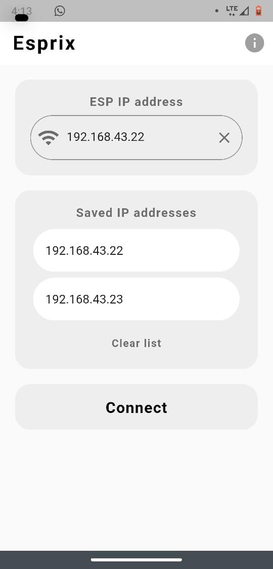
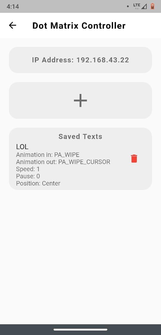
I made this app using Flutter to control the Dot matrix via Wifi.
App Features:
- Multiple IP Address Storage: Esprix empowers users to effortlessly store and manage multiple IP addresses, making it easy to control a variety of displays from a single interface.
- Versatile Text and Settings Storage: With Esprix, you can conveniently store multiple texts along with their customizable settings. This feature provides flexibility in displaying various messages on the connected display, tailored to your preferences.
- Fast and Responsive: Experience the speed and responsiveness of Esprix as it enables smooth and instantaneous control of your display, ensuring a seamless user experience.
- Intuitive and Simple UI: Esprix boasts an intuitive and user-friendly interface, making it accessible to users of all levels of tech expertise. The app's straightforward design ensures hassle-free navigation and operation.
- Open Source: Esprix is an open-source project, welcoming contributions from the community to enhance its features and functionality. Visit our GitHub repository at https://github.com/yash-ch/esprix to contribute and collaborate.
- Ad-Free Experience: Enjoy uninterrupted usage with Esprix - the app is designed without any ads, ensuring a clean and distraction-free environment.
APK for android is attached.
Downloads
Hole in Bag and Final Attachment


Attaching the display to the bag can be done following these steps:
- Prepare the Bag:
- Identify the locations on the bag where you want to attach the display. Use the holes provided in the top 3D printed part as a reference.
- Mark the positions for the holes on the bag's surface using a marker or chalk.
2. Make Holes in the Bag:
- Carefully cut or punch holes in the bag at the marked positions using scissors, a hole punch, or a suitable tool.
- Additionally, create a hole or slot on the bag for passing the wires from the display to the circuit inside.
3. Position the 3D Printed Parts:
- Place the top 3D printed part with the display on the outside of the bag, aligning the holes on the part with the holes in the bag.
- Insert the bottom 3D printed part (with the ESP8266 D1 mini holder) inside the bag, aligning it with the top part on the outside.
4. Secure the Parts Together:
- Insert screws through the holes in the top 3D printed part and thread them into the corresponding holes on the bottom part inside the bag.
- Tighten the screws to securely fasten the two parts together, sandwiching the bag material in between.
5. Connect the Wires:
- Pass the wires from the display through the hole or slot in the bag and connect them to the circuit you made on the perfboard (ESP8266 D1 mini holder) inside the bag.
- Ensure the connections are secure and well-insulated to prevent any short circuits or loose connections.
6. Final Check:
- Before closing the bag, make sure all the components are properly positioned and secured.
- Double-check the circuit connections to ensure they are accurate and without any issues.
Once you've completed these steps, your display should be firmly attached to the bag and ready to be powered and controlled using the app you developed. Enjoy showcasing messages and information on the go!
Final Words

Congratulations! Your tutorial has reached its completion, and you now have a fully functional project that can be powered using a power bank or battery connected via the male header pins. This feature adds flexibility and mobility to your display, allowing you to showcase messages wherever you desire.
Feel free to enjoy your completed project and consider sharing videos or images with others to showcase your creation. Sharing your success can inspire and motivate fellow makers and enthusiasts in the community.
Don't forget to emphasize the importance of contributing to the app you developed. Encouraging others to contribute to open-source projects fosters a collaborative spirit and leads to continuous improvement and innovation.
Thank you for taking this tutorial journey with me. I hope it has been a valuable learning experience, and I wish you the best in all your future projects. Happy making and coding!