Glowtie V2 - a Glowing Bowtie
by Donut Studio in Circuits > Wearables
739 Views, 4 Favorites, 0 Comments
Glowtie V2 - a Glowing Bowtie


The Glowtie V2: more glow for less (bow)tie!
Ever since I built Raxathor's adaptation of the Glowtie, it became one of my favorite projects. My first version had a pretty solid base. It included a button, more effects and an improved webserver. Soon I decided to create a new, up-to-date version - Glowtie V2.
The new version should have a dedicated bluetooth app for controlling effects, react to music and have even more leds. It should also look way better than my last attempt. I had to start from the beginning again: designing a new pcb, soldering all the components and programming the MCU...
As always, the project files can be found on this github repository:
https://github.com/KonradWohlfahrt/GlowtieV2
Note: This project is sponsored by PCBWay. While I can create a circuit digitally, producing the circuit board myself is way out of scope. The process is difficult and without proper machinery/tools, complex, multilayer boards are impossible to build yourself. Fortunately, you can find companies like PCBWay, which are able to take your digital design and fabricate the pcbs for a low price! Such quality cannot be achieved as a hobbyist. That's why I reached out to them and had the pcbs produced by them! Thanks to PCBWay for sponsoring the printed circuit boards!
Supplies

To build the Glowtie V2 you will need a few components as well as tools. The part list (with pcb labels) can be found at my github repository.
Components:
- custom pcb
- 3d printed case
- 500mAh lipo battery
- 2x M3x6 screw with nut
- 100uF 1206
- 2x 1uF 0805
- 3x 10uF 0805
- 20x 100nF 0805
- LED red 0805
- LED green 0805
- 17x WS2812b 5050
- 3k 0805
- 100r 0805
- 330r 0805
- 33k 0805
- 3x 1k 0805
- 5x 10k 0805
- TP4056
- DW01A
- FS8205A
- MCP1826S-3302, MIC39100-3.3WS or similar LDO
- ESP32-C3-WROOM-02-H4
- 2x SMD button 3*6*2.5
- USB Type-C 4 pin
- SK12D07VG6
- INMP441 (optional)
- Ribbon (optional, for case)
Tools:
- Soldering Iron (or reflow hot plate/oven) + solder + tweezers
- FTDI UART Programming Board + dupont cables
- PC with Arduino IDE
Circuit & PCB Design


Instead of the ESP8266, the ESP32-C3 will be the heart of the new Glowtie. Its Bluetooth Low Energy and I2S communication will be perfect to expand upon the features! The LiPo Battery will be charged via USB-C by the common TP4056 charge IC. The MCP1826S-3302 LDO (or similar) will reduce the battery voltage to 3.3V and power the ESP as well as the I2S microphone. A few capacitors were added to reduce power spikes and a voltage divider reduces the battery voltage to a readable level for the ADC.
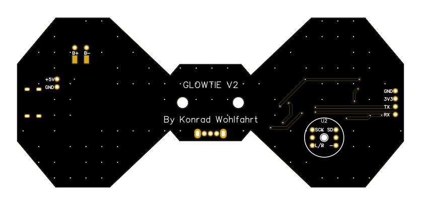
The new pcb turned out to be a little bit smaller than the last one eventhough it has four more leds.
With the gerber files generated, I ordered the pcbs from PCBWay. I received them a week later. They look awesome, especially with the black solder mask. I was satisfied with the quality and began to solder the components.
Note: During programming I discovered a major flaw! I connected one pin of the I2S microphone to a GPIO that cannot be used together with WiFi! Thus, I had to remove the audio visualizer from the WiFi version. Always make sure to read your MCU datasheets completely! I will probably upload a new gerber file without this issue, but you have to change the I2S pins in the code.
Soldering


I ordered the pcb without silkscreen labels. This makes it a bit hard to find the exact place for the component. If your circuit board includes lables, you can just follow the table provided at my github repository, otherwise use the picture as reference. SMD components should be soldered first. Start from the inside and work your way outwards.
The unlabled components close to the leds are 100nF capacitors.
A heatplate can make soldering more convenient and faster. But if you don't have a heatplate at your disposal (like me), it is possible to build the V2 with just a soldering iron and a small tip. I do not recommend to use this project as a beginner, as soldering SMD components takes practice.
Finally, find a suitable LiPo battery (for example 500mAh) and solder it to the pads on the back. The charge programming resistor (R1) of the TP4056 can be changed to adjust the charge current. Take a look at the TP4056 datasheet for more information! 3k Ohms should be fine for 400 to 500mAh batteries!
3D Case


While soldering you should start your 3d printer or if you don't own one, order the parts together with the pcbs.
Depending on how you want to secure the pcb, I created two different enclosures. The first slides on the button of your shirt, while the other one can be used together with a ribbon and tightened around the neck. The pcb is secured to it via two M3 screws. Add the bumper on top for a cleaner look and further protection. For a more elegant look, place the diffuser on top of the bumper! Keep in mind that if you want to access the buttons, print `Diffuser Cutout` and the corresponding button raiser.
Unfortunately, the pins of the on/off switch can obstruct the button. You might want to trim them a little. Just make sure to avoid shorting the battery and disconnect it first!
That concludes the hardware part and we can focus on the software!
Programming

The programming is straight forward! First of all, you have to setup your Arduino IDE and install the FTDI drivers. I'm not going to explain this process as you can find great blogs and videos on this topic online. Install the ESP32 board manager and the Adafruit Neopixel, WS2812b FX and arduinoFFT (and ESPAsyncWebServer for the WiFi Version) Library. You probably want to change the name/ssid (and password) before uploading.
Connect the FTDI programmer (3.3V!) to the Glowtie as follows:
FTDI -> Glowtie
VCC -> 3V3
GND -> GND
TX -> RX
RX -> TX
Do not plug in the FTDI programmer yet! First, press the upper button (Label - SW2), also known as Flash and connect the programmer to your pc. Do not let go of the button until the sketch started uploading! Select the corresponding port, board: `ESP32C3 Dev Module` and press upload. If everything worked, the sketch should be uploaded to the MCU and you can unplug the cables. If everything worked correctly, your Glowtie should light up.
There are three versions you can upload to your Glowtie:
Mic Version:
- has music reactive effects
- can only be controlled via buttons (limited options)
WiFi Version:
- no music reactive effects
- connect to your Glowtie via WiFi and open the website/ip (192.168.4.1) in your browser
- works on any device with WiFi and browser
BLE Version:
- has music reactive effects
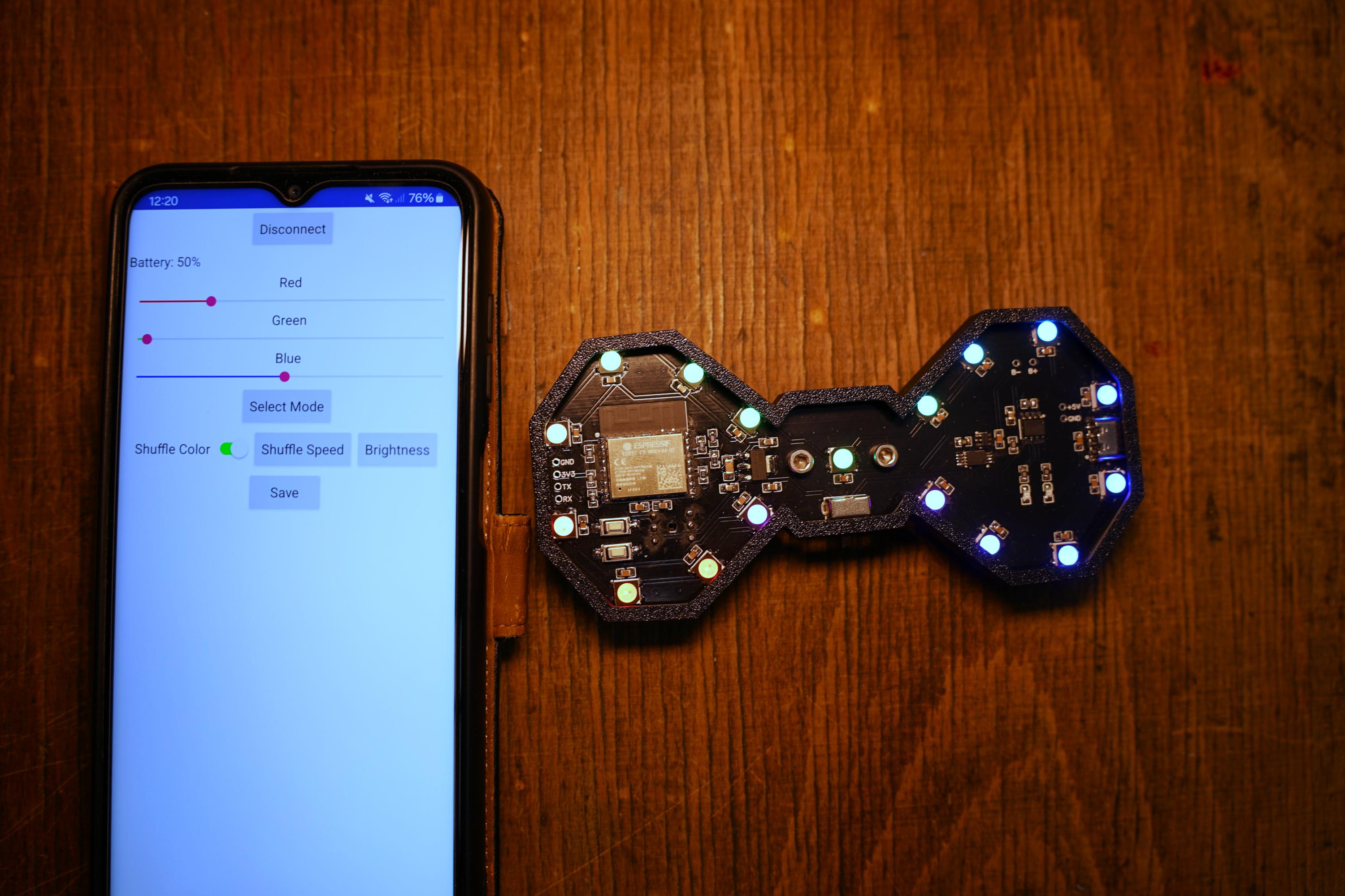
- connect to your Glowtie via BLE with a dedicated App on your phone
- only works with the App
You might want to upload the WiFi version and adjust the mode, color and preferences. Press the save button (webserver) to permanently write the preferences to the EEPROM. Press and hold the upper button to save the mode and color to EEPROM. Now you can upload the Mic version and the Glowtie will boot with your selected options.
These are the following button functions:
- short press B1: show battery status
- short press B2: shuffle mode
- long press B1: save mode and color to eeprom
- long press B2: music mode
- double press B1: start BLE advertising (ble version) / swap to next effect + color (mic version)
Custom Effects


You can try and add your own effects to the Glowtie or change existing ones. Utilize the 'GlowtieEffect' class:
Now you just have to add your effect to the main .ino sketch and adjust the array length. If you have added more effects, you also have to change the app or webserver.
BLE Communication


BLE can have many advantages! With the main arguments for this project being:
- less power consumption than WiFi
- phone can still be connected to WiFi while also changing effects
- app is more convenient and simple to use
- the music reactive mode does not work together with WiFi (due to schematic design error)
The following playlist on Youtube helped me to get comfortable with BLE on ESP32. I highly encourage you to watch it:
https://www.youtube.com/playlist?list=PL94tI_1M51VWwqCMGSpFWTzUbsezOPoJ4
Setting up the BLE server was easy and with the nRF Connect App I was able to see the characteristics and update them. The hard part is coding the app for my phone. I don't have much experience in app development and my first way to go was the cross platfrom framework React Native. Learning a new programming language and framework takes a lot of time. That's why I abandoned it soon and picked up MIT App Inventor. MIT App Inventor might be the easiest way to create applications. It's intuitive, simple and fast, though the final design suffers a bit! You can inspect and build my app by importing the .aia file. If you changed the UUIDs in the Arduino IDE, you also have to change them in the project.
I might come back to try a different approach, until then the MIT App should do the job!
Summary


That concludes the new Glowtie version!
You can charge the battery via the USB-C port on the side and just have fun with the awesome led effects! I like the look of the electronics and black pcb, that's why I did not add a diffuser. The quickest and easiest approach would be to put paper between the pcb and bumper.
I hope you found this guide helpful and interesting! I'd be happy to see you build the Glowtie yourself.
Finally, special thanks to PCBWay for supplying me with the circuit boards!
Until next time :)