Google Home Controlled Beer Launcher
by neil_b111 in Circuits > Robots
508 Views, 1 Favorites, 0 Comments
Google Home Controlled Beer Launcher
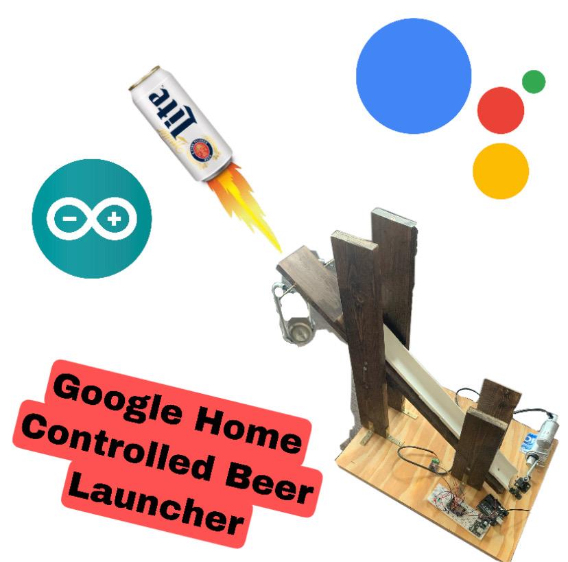
I just graduated college and moved to a new city to start my career as an engineer when all of a sudden the pandemic hit and I was stuck in my tiny one bedroom apartment.
After feeling like I just about watched everything on Netflix and was reaching peak boredom in quarantine, I decided to build something! What is better than building a voice controlled beer launcher to shoot myself drinks while I kick my feet up and relax on the couch.
My goal for this project was to build this device at a very low cost utilizing lots of resources around me as well as to learn more about engineering.
I ended up completing this project even though at times I felt defeated, I kept persevering until it was a success. I ended up going viral on social media for it and felt like not only did I put a smile on my face, but a smile on the thousands of others who viewed it during a time when the world could use a good smile. I hope you enjoy!
Video of the Device


Supplies


SUPPLIES LIST
NodeMCU (Amazon Link)
Breadboard/Jumper Wires
Linear Actuator (Amazon Link)
Power Supply Module
Red and Green LEDs
Power Adapter Supply
Motor Controller Drive (Amazon Link)
Door Latch (Trigger mechanism) (Link)
Custom made Beverage Holster
Wood/Screws/PVC Piping
Slingshot Cord (Amazon Link)
Brackets (Link)
Plastic Holder
Picture Hanger Hook (Link)
Screw Eye Hook (Link)
Saw
Drill
Wood Stain
Laptop/Phone
Note: A lot of these supplies were gathered from an Arduino Starter Kit (Amazon Link). This is a great kit if you are just starting out with a lot of cool supplies and tutorials.
Building the Launcher


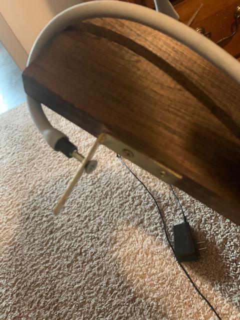
I wouldn't call myself a carpenter but I think this launcher turned out pretty good. There are hundreds of other ways this could have been built, but this was my take on the device. Much of the screws and brackets used to build this I found lying around my apartment and the wood I picked up from the scrap section at Home Depot.
STEPS
- Cut two large planks of wood approx. 2 feet each and screw them into a square wooden base vertically at the edge of the base board, approx. 4 inches apart, using some screws and brackets as support
- Repeat this process with two small planks of wood, approx. 1 foot each, towards the opposite edge of the base board.
- Place a single piece of wood approx. 2.5 feet long at a 45 degree angle between the pairs of vertically fixed planks and screw the plank into place going through the sides of the vertical planks.
- Cut the PCV pipe in half vertically so it is just small slide segment.
- Place the PVC pipe on top of the angled plank and screw into place.
- Screw two brackets at the top side edge of the angled plank, and place a screw into each bracket (see picture).
- At the base of the angled plank, screw down the door latch.
- Using an old beer can, cut it into a sleeve and screw it into the slingshot using the screw eye. (The sleeve is used as support to hold the can; see attached video below.)
- Attach the Picture Hanger Hook through Screw Eye.
- Connect Slingshot to screws in the brackets at the top of the angled plank.
- Attach Linear Actuator to base board, near the door latch, and holster down using a plastic holder. (In my case I cut up and old mouthwash bottle).
- Attached Linear Actuator to door latch using screw hooks.
- Stain the wood (outdoors) or decorate to however you please.
Setting Up Blynk
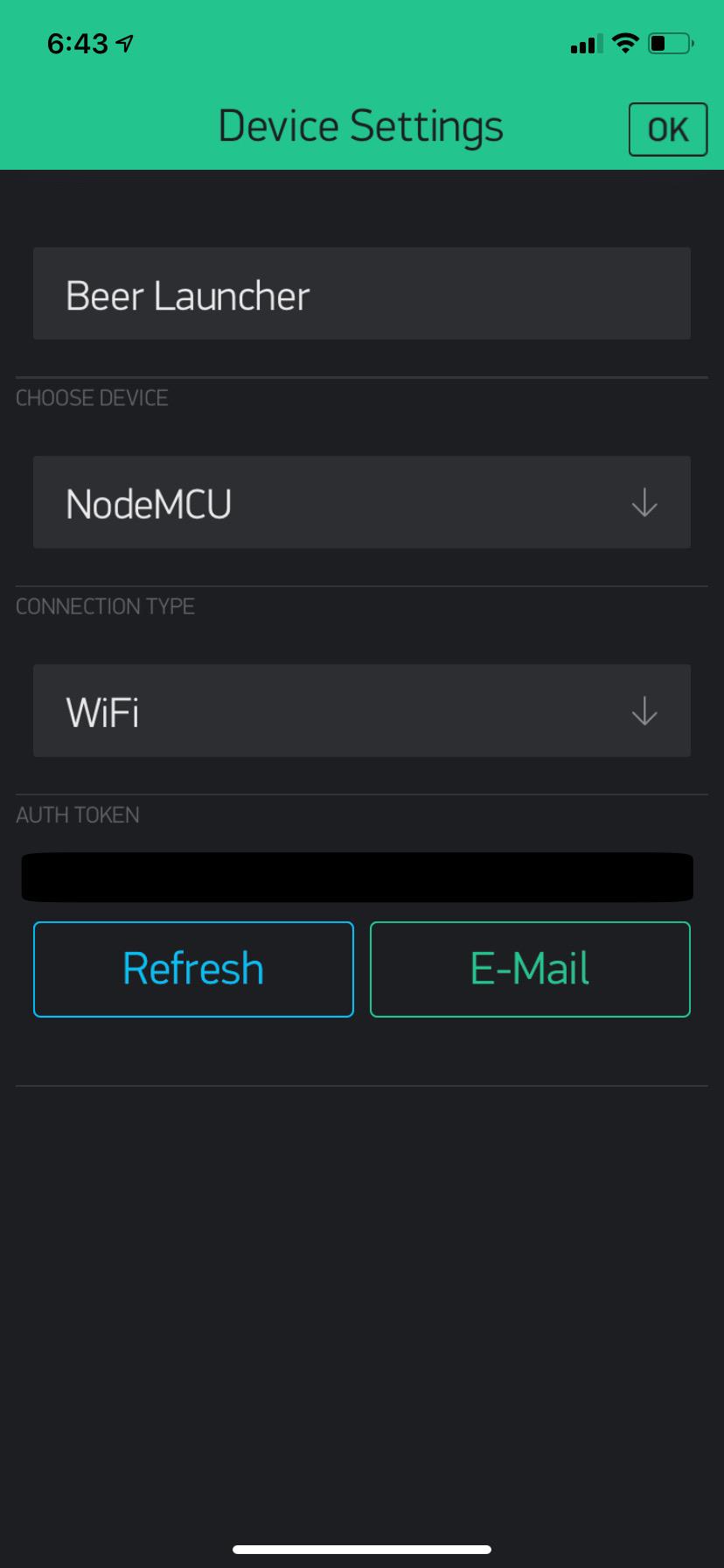


STEPS
For an in-depth guide for setting up Blynk and starting a new project please go here.
- Download Blynk app on your phone, set up an account if needed, and start a new project.
- For device, choose NodeMCU. For connection, type choose WiFi.
- Take note of the Auth Token.
- Add two button widgets to your canvas
- The first button will be the FIRE button. This button, when activated, initiates the code to contract the linear actuator pulling the door latch open, releasing the slingshot, and firing the device. Make the proper attribute changes, to the buttons, based on the pictures above.
- The second button will be the RESET button. This button when activated initiates the code to extend the linear actuator pushing the door latch closed. Make the proper changes based on the pictures above.
- Push the play button in the top right corner to run the project.
Note: Click on more pictures to see all of the photos
Setting Up Google Assistant Integration


STEPS
Note: Click on more pictures to see all of the photos
- Go to IFTTT.com and set up an account based on the account you use for your Google Home.
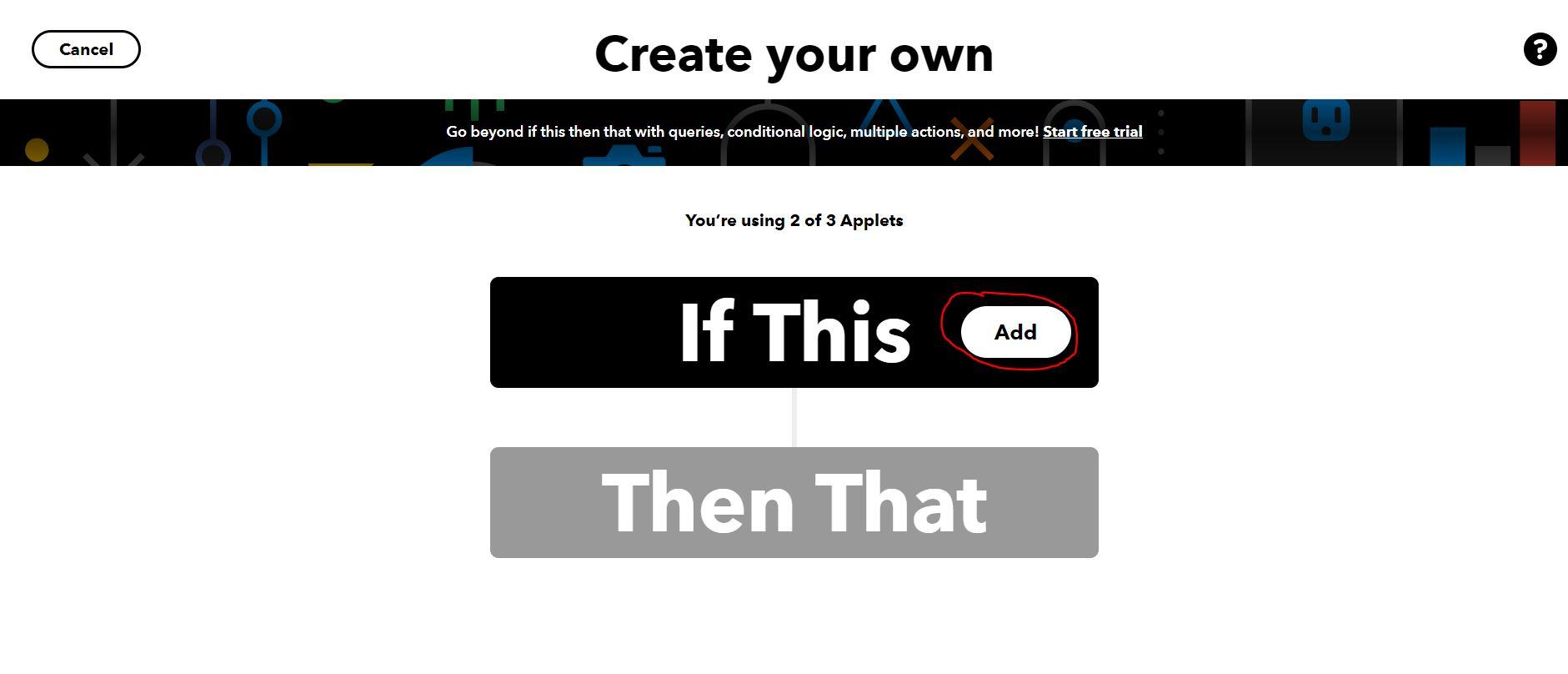
- Create a new Applet by going to My Applets and then Create.
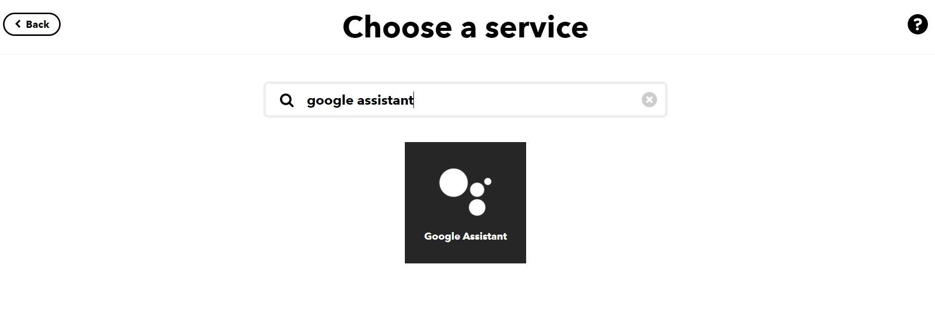
- Click on "If This" and then search for "Google Assistant" and select it.
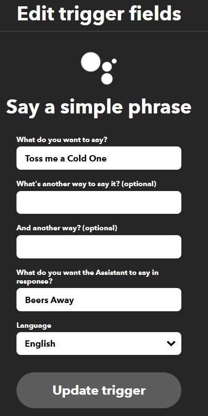
- You have multiple options to select from. Choose "Simple Phrase".
- Add the phrase you want to say to your Google Home to activate the launcher. In this case I am using, "Toss me a Cold One"
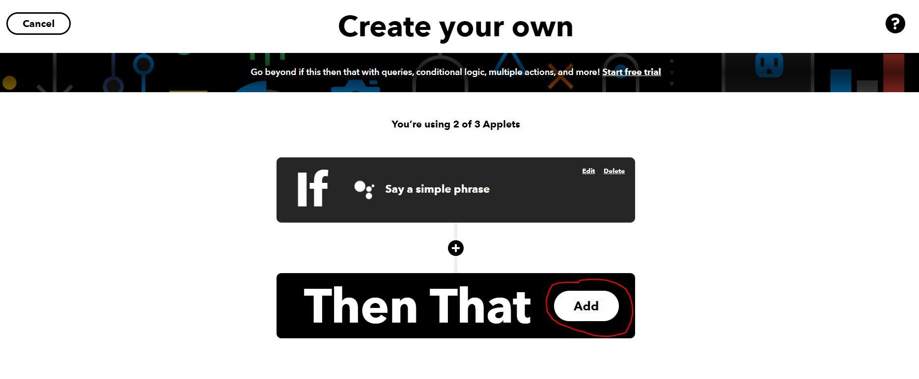
- Add in how you want your Google Home to respond and click "Create Trigger".
- Click on "Then That" and search for "Webhooks" and select it.
- For URL enter... https://45.55.96.146/AUTH TOKEN/update/V0 ... but switch out AUTH TOKEN with the token created in Blynk
- For Method use "PUT", for content type use "application/json", and for Body use ["1"]. Click Create Trigger.
Your Google Home is now connected to your Blynk Project. When you say the phrase you created it will now trigger the FIRE button in the Blynk app. Next we are going to use ArduinoIDE to link your Google Home and your Blynk Project to your Linear Actuator.
Wiring Up the Device

STEPS
Follow along using the diagram above I created, using Fritzing, and the following steps below to see how the device was wired.
- Insert the Power Supply Module onto the top on the Breadboard with the jumper cap placed on the 5V output pin on one side of the breadboard (column A) and the jumper cap removed from the other side of the breadboard (column B). Power the Power Supply Module using a Power Adapter (up to 12V).
- On the opposite side of the breadboard (column B) power the columns using an external power supply (up to 12V) for the Linear Actuator.
- Motor Controller Driver Port A-1B to D7 on NodeMCU (Yellow Wire).
- Motor Controller Driver Port A-1A to D6 on NodeMCU (Purple Wire).
- Motor Controller Driver Port VCC to Positive Terminal on the Breadboard column B.
- Motor Controller Driver Port GND to GND on the Breadboard column B.
- Linear Actuator Black Wire to Outside Terminal of Motor A on the Motor Controller Driver.
- Linear Actuator Red Wire to Inner Terminal of Motor A on the Motor Controller Driver.
- NodeMCU GND to Breadboard GND column A
- NodeMCU Vin to Breadboard Positive column A
- Insert the Red LED (+) wire into an empty space on the breadboard and then wire it to D1 on NodeMCU (Red Wire)
- Insert the Red LED (-) wire into the GND of column A.
- Repeat the process with a Green LED (Green Wire)
Now that everything is finished wiring up. We can move on to the Arduino IDE coding.
Setting Up Arduino IDE


STEPS
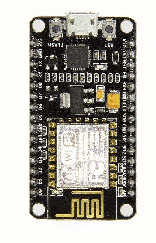
Note: The first image shows how the NodeMCU Pins relate to Arduino Pins. ArduinoIDE uses the Arduino Pin nomenclature so you must convert them over i.e. Pin D1 on the NodeMCU is Pin 5 on the Arduino
- Download ArduinoIDE, the NodeMCU Library, and the Blynk Library from the following links (Arduino, NodeMCU Library, Blynk Library).
- Launch Arduino IDE and plug in your NodeMCU using a Micro USB.
- Go to Tools and select the correct COM PORT the NodeMCU is plugged into.
- Go to File > Examples > Blynk > Boards_WIFI > ESP8266_Standalone and select it.
- For Boards make sure Generic ESP8266 Module is selected. Go to Tools > Boards and select Generic ESP8266 Module.
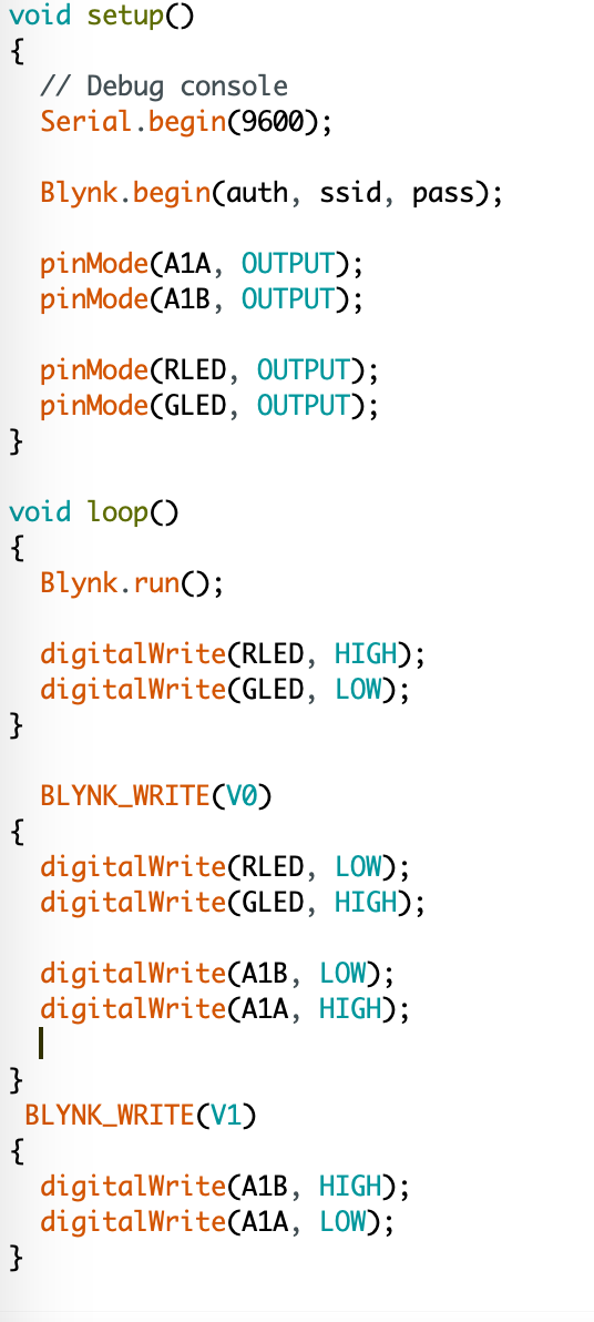
- A skeleton ArduinoIDE code will open where you can now fill in the proper code to get the device to work in. First change the "YourAuthToken", "YourNetworkName", and "YourPassword" to your Blynk Auth Token, your WiFi Network name, and your WiFi Password respectively.
- Begin inserting the ArduinoIDE code following along with the images.
How the Program Works
When you say the simple phrase, "Hey Google, Toss me a Cold One!", the webhook we created using the IFTTT connects to the Blynk project we made activating the button we created. Once the the button is activated, through WiFi, the code runs on the Arduino, activating the linear actuator, tossing you a nice crisp cold one. Cheers!
Cheers!!

Congrats! We have officially completed the voice controlled beer launcher! I hope you enjoyed this instructable as much as I did making it. Feel free to reach out to me if you have any questions or comments about this instructable and stay tuned for feature projects.