Grove 3 Axis Digital Compass
by ThisIsSteve in Circuits > Arduino
4937 Views, 8 Favorites, 0 Comments
Grove 3 Axis Digital Compass


This is the fourth tutorial of a series of tutorials where I show you how to connect Grove sensors and Components to an Arduino and to get started for a robot project using these sensors. In the last few instructables, I showed how to get started with I2C Motor Driver, Single Axis Analog Gyro and a Thumb Joystick, also check that out if you are here for the robot build.
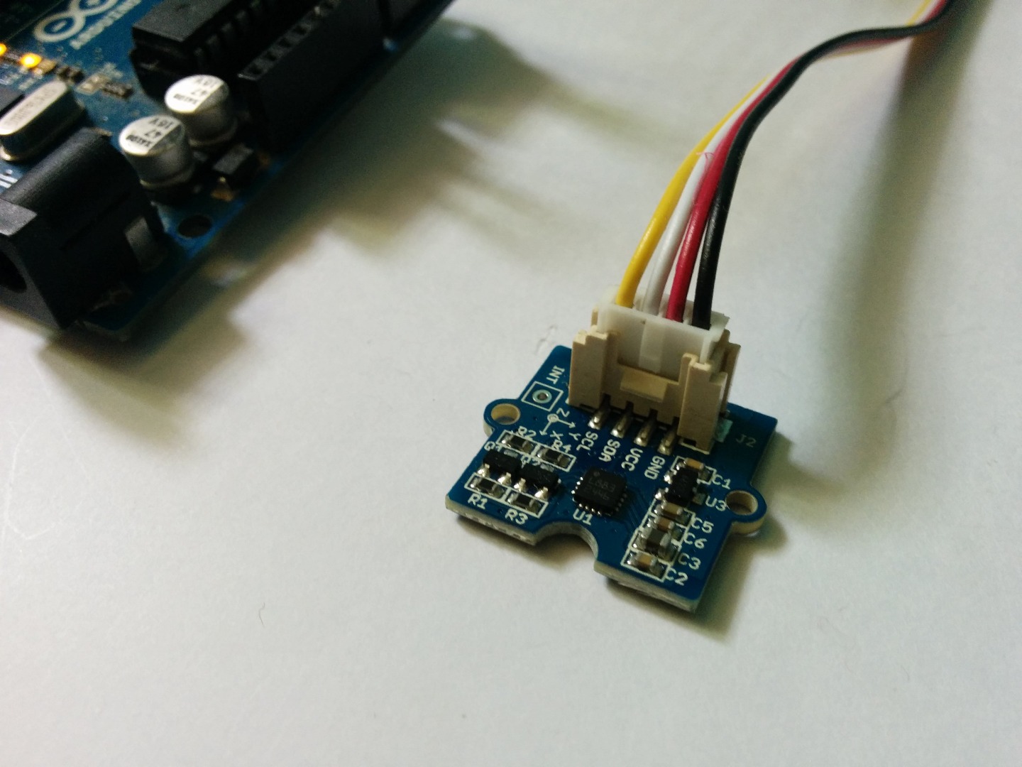
In this tutorial I'm going to show you how to get started with a Grove three Axis Digital Compass with an Arduino.
So lets get started.....
Tools and Components

All that you need for this tutorial is-
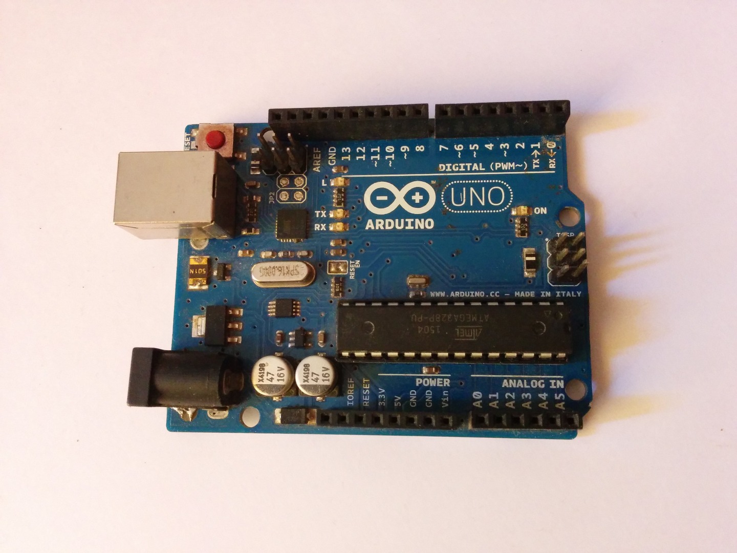
- Arduino UNO
- Grove 3 Axis Digital Compass
- Jumper wires
Note- No soldering skills are required to build this project, but it is good to know how to solder there are a good soldering tutorials on YouTube that can help you get started.
Getting Started

I2C is a is 2 pin communication system the 2 lines are the SDA (data line) and SCL (clock line), this reduces the number of pins of the Arduino dedicated to drive the Digital Compass. There is a good documentation of Arduino I2C in the Arduino website, you can read to that to get started with I2C.
Hardware

Now time for the connections the Arduino has the SCL line on analog pin 5 and SDA line on analog pin 4.
Here is how you need to connect he hardware -
- Arduino analog pin 5 - Grove I2C Motor Driver SCL
- Arduino analog pin 4 - Grove I2C Motor Driver SDA
- Arduino +5V - Grove I2C Motor Driver VCC
- Arduino Gnd - Grove I2C Motor Driver Gnd
After you connect the hardware it is time to upload the code......
Code


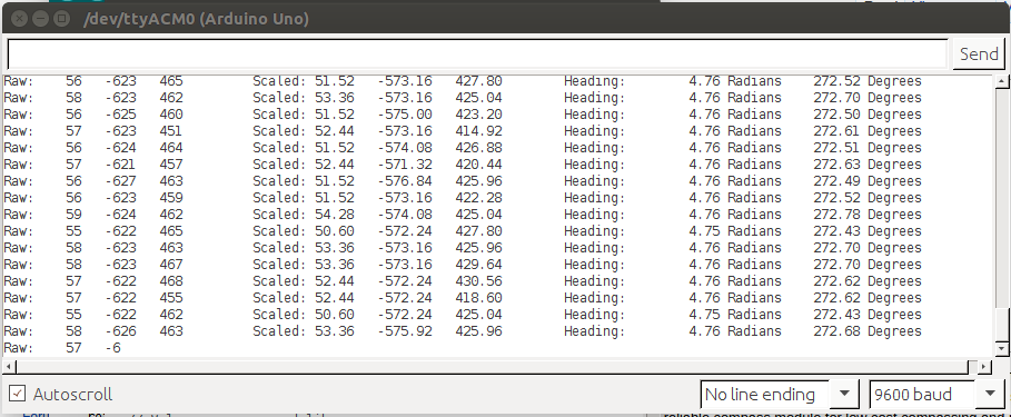
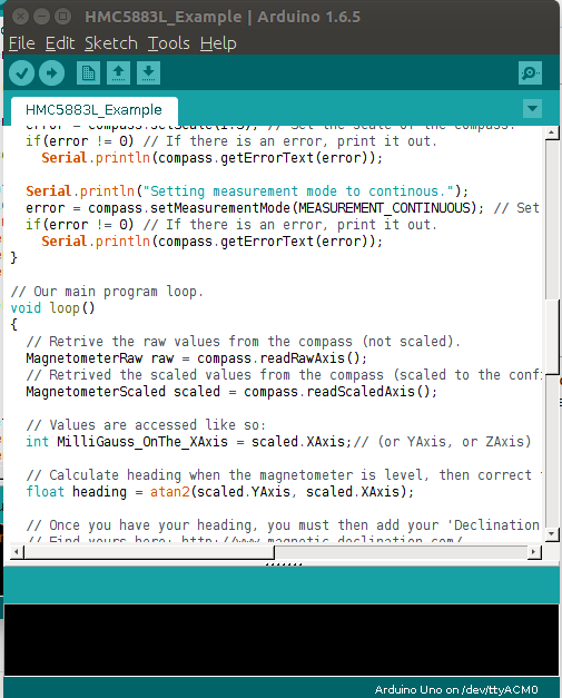
The code is quite simple and all it does is reads the compass readings and prints it out on a serial monitor. The Compass calibrates for a few seconds when you run the code make sure not to rotate or disturb the compass while this happens and after it completes you should get a fine stream of data from the sensor.
<p>// Reference the I2C Library<br>#include <wire.h>
// Reference the HMC5883L Compass Library
#include <hmc5883l.h></hmc5883l.h></wire.h></p><p>// Store our compass as a variable.
HMC5883L compass;
// Record any errors that may occur in the compass.
int error = 0;</p><p>// Out setup routine, here we will configure the microcontroller and compass.
void setup()
{
  // Initialize the serial port.
  Serial.begin(9600);</p><p>  Serial.println("Starting the I2C interface.");
  Wire.begin(); // Start the I2C interface.</p><p>  Serial.println("Constructing new HMC5883L");

  Serial.println("Setting scale to +/- 1.3 Ga");
  error = compass.setScale(1.3); // Set the scale of the compass.
  if(error != 0) // If there is an error, print it out.
    Serial.println(compass.getErrorText(error));

  Serial.println("Setting measurement mode to continous.");
  error = compass.setMeasurementMode(MEASUREMENT_CONTINUOUS); // Set the measurement mode to Continuous
  if(error != 0) // If there is an error, print it out.
    Serial.println(compass.getErrorText(error));
}</p><p>// Our main program loop.
void loop()
{
  // Retrive the raw values from the compass (not scaled).
  MagnetometerRaw raw = compass.readRawAxis();
  // Retrived the scaled values from the compass (scaled to the configured scale).
  MagnetometerScaled scaled = compass.readScaledAxis();

  // Values are accessed like so:
  int MilliGauss_OnThe_XAxis = scaled.XAxis;// (or YAxis, or ZAxis)</p><p>  // Calculate heading when the magnetometer is level, then correct for signs of axis.
  float heading = atan2(scaled.YAxis, scaled.XAxis);

  // Once you have your heading, you must then add your 'Declination Angle', which is the 'Error' of the magnetic field in your location.
  // Find yours here: http://www.magnetic-declination.com/
  // Mine is: -2��37' which is -2.617 Degrees, or (which we need) -0.0456752665 radians, I will use -0.0457
  // If you cannot find your Declination, comment out these two lines, your compass will be slightly off.
  float declinationAngle = -0.0457;
  heading += declinationAngle;

  // Correct for when signs are reversed.
  if(heading < 0)
    heading += 2*PI;

  // Check for wrap due to addition of declination.
  if(heading > 2*PI)
    heading -= 2*PI;

  // Convert radians to degrees for readability.
  float headingDegrees = heading * 180/M_PI; </p><p>  // Output the data via the serial port.
  Output(raw, scaled, heading, headingDegrees);</p><p>  // Normally we would delay the application by 66ms to allow the loop
  // to run at 15Hz (default bandwidth for the HMC5883L).
  // However since we have a long serial out (104ms at 9600) we will let
  // it run at its natural speed.
  delay(66);//of course it can be delayed longer.
}</p><p>// Output the data down the serial port.
void Output(MagnetometerRaw raw, MagnetometerScaled scaled, float heading, float headingDegrees)
{
   Serial.print("Raw:\t");
   Serial.print(raw.XAxis);
   Serial.print("   ");
   Serial.print(raw.YAxis);
   Serial.print("   ");
   Serial.print(raw.ZAxis);
   Serial.print("   \tScaled:\t");

   Serial.print(scaled.XAxis);
   Serial.print("   ");
   Serial.print(scaled.YAxis);
   Serial.print("   ");
   Serial.print(scaled.ZAxis);</p><p>   Serial.print("   \tHeading:\t");
   Serial.print(heading);
   Serial.print(" Radians   \t");
   Serial.print(headingDegrees);
   Serial.println(" Degrees   \t");
}</p>