Hack a Broken Smartwatch: Reverse Engineering & Custom Firmware Guide
by DsnIndustries in Circuits > Wearables
159 Views, 1 Favorites, 0 Comments
Hack a Broken Smartwatch: Reverse Engineering & Custom Firmware Guide
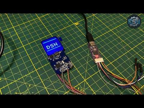
Upcycle a discarded commercial smartwatch into an open-source development board powered by the Nordic nRF52832 SoC.
Supplies
Hardware
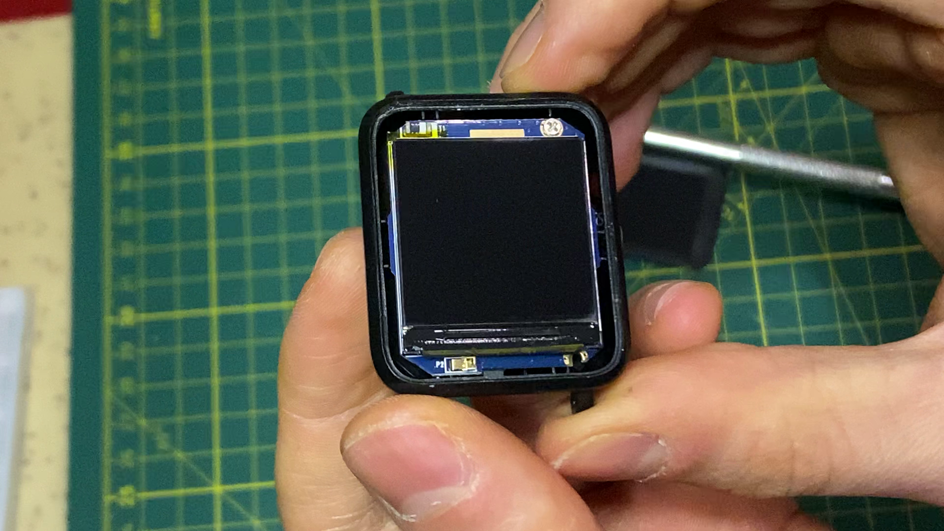
Old/broken smartwatch with an nRF52832 SoC, 1.69" SPI LCD module, LiPo battery
Flashing & Debug
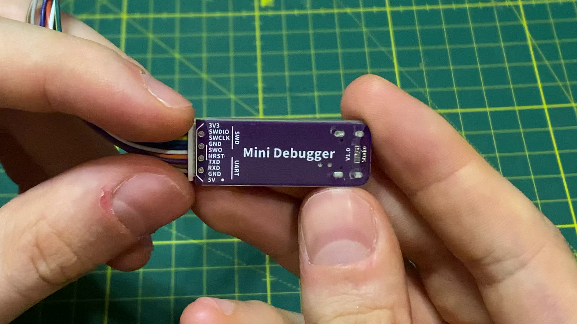
Mini JTAG/UART debugger tool, ESP32 development board (for DAP unlocking)
Probing & Assembly
Digital multimeter, soldering iron, thin jumper wires, flux, and solder
Software
VS Code, Nordic nRF SDK, OpenOCD, Adafruit nRF52 Bootloader (.hex)
Teardown & Chip Identification
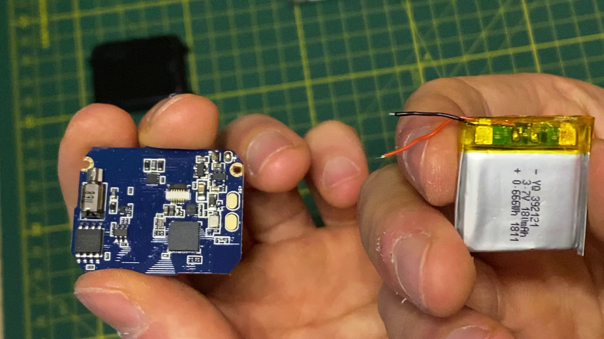
Carefully disassemble the smartwatch casing to expose the internal PCB.
- Clean off adhesive or shielding tape to locate the main microcontroller.
- Identify the SoC package markings (confirming the Nordic nRF52832).
- Locate the surrounding hardware: power delivery/charging IC, battery leads, onboard gyro/accelerometer, and display ribbon connector.
Map the Pins Blind (Multimeter Probing)
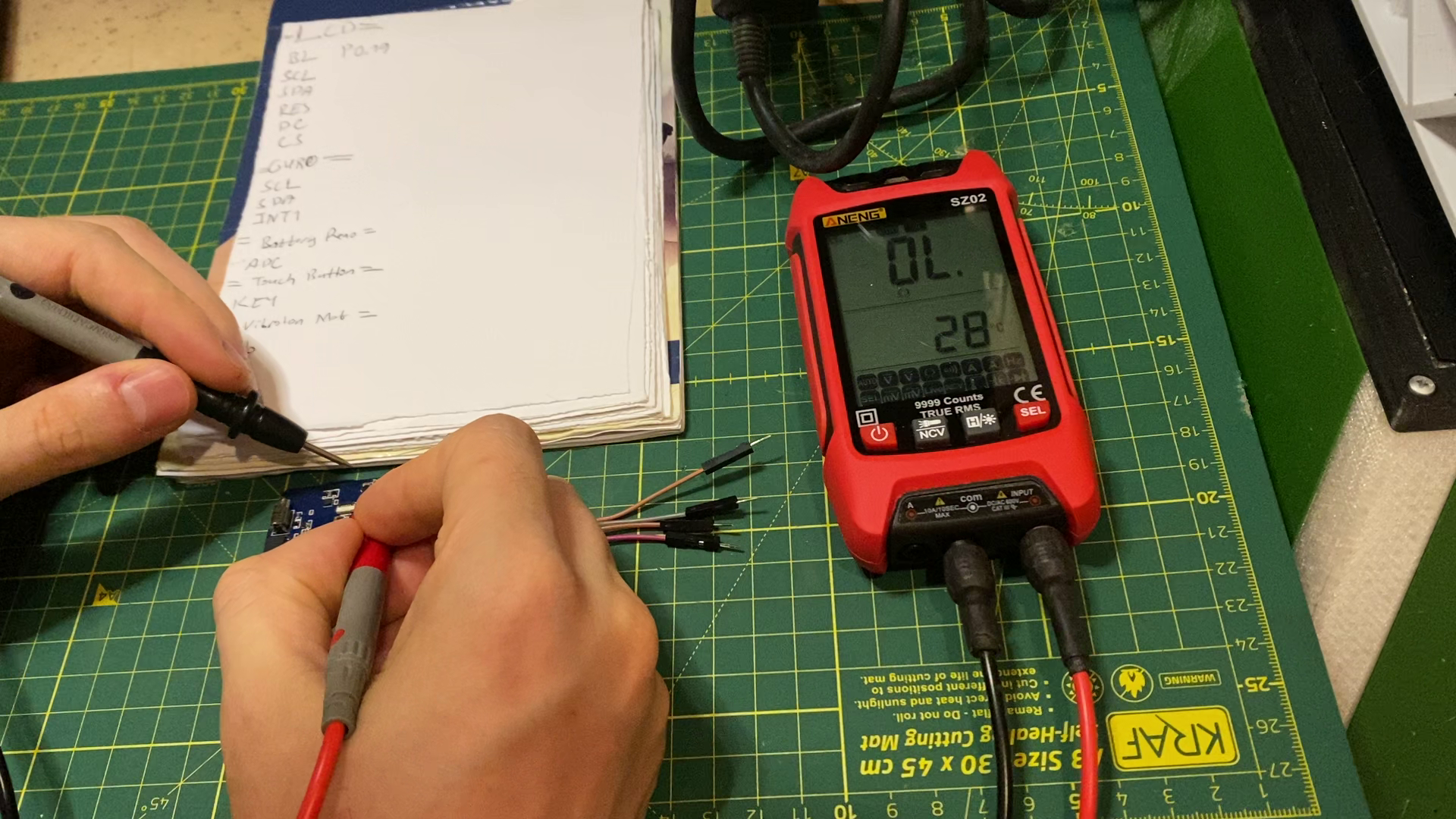
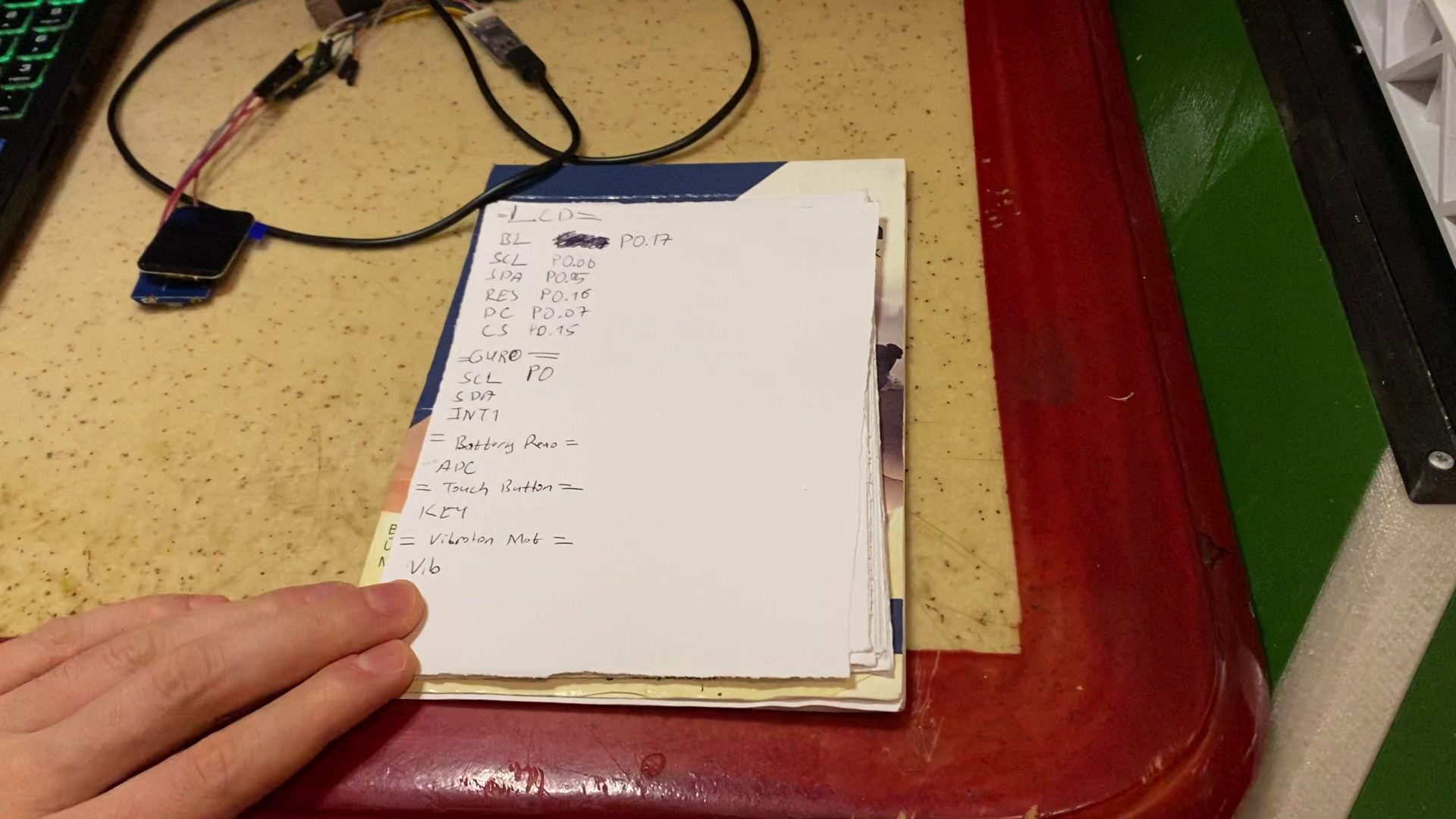
Because schematics are unavailable for commercial consumer wearables, map connections manually:
- Set your digital multimeter to Continuity / Short-Circuit Mode.
- Match display connection pads to their corresponding pins on the nRF52 package. Note down SPI lines: SCK, MOSI, CS, DC, and RESET.
- Trace the onboard gyro sensor traces by visually following PCB routes and testing accessible test pads.
- Identify the SWD/JTAG debug access points (SWDIO, SWDCLK, GND, VCC) on the board.
Unlock the NRF52 Write Protection (ESP32-DAP)
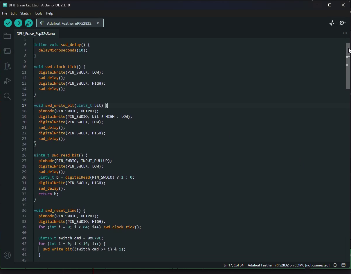
Factory nRF52 chips generally have Access Port Protection (APPROTECT) enabled, preventing external writes.
- Connect the smartwatch SWD pins to the ESP32 programmer.
- Run the ESP32-DAP utility to clear the factory write protection flags from the chip registers.
- Verify that the debug interface returns an unlock/success confirmation.
source file : https://github.com/derdacavga/Nrf52832-Unlocker
Flash the Adafruit Bootloader Via OpenOCD
.png)
.png)
- Solder thin jumper wires between your mini JTAG debugger and the smartwatch SWD test points.
- Download the compatible Adafruit nRF52 bootloader .hex binary.
- Launch OpenOCD in your terminal and flash the bootloader image onto the nRF52832.
- Power cycle the board to verify the new bootloader initializes.
Adafruit Bootloader: https://github.com/adafruit/adafruit_nrf52_bootloader
OpenOCD: https://github.com/openocd-org/openocd
Build and Flash Custom Firmware
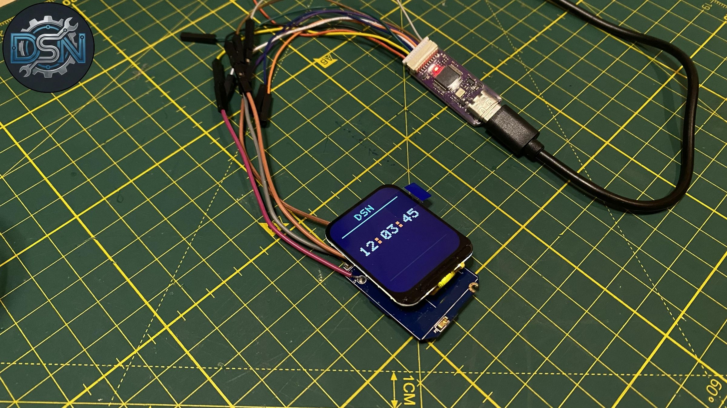
- Open the Nordic nRF SDK inside VS Code.
- Select a baseline sample project (such as a Bluetooth Low Energy peripheral LBS demo).
- Map your newly discovered display and sensor pin definitions inside the board configuration header.
- Compile the project to generate a .hex binary. (file in ProjectName\build\ProjectName\zephyr\zephyr.hex)
- Flash the binary to the board using OpenOCD or Vs code nRF terminal.
Wire the Upgraded Display & Test
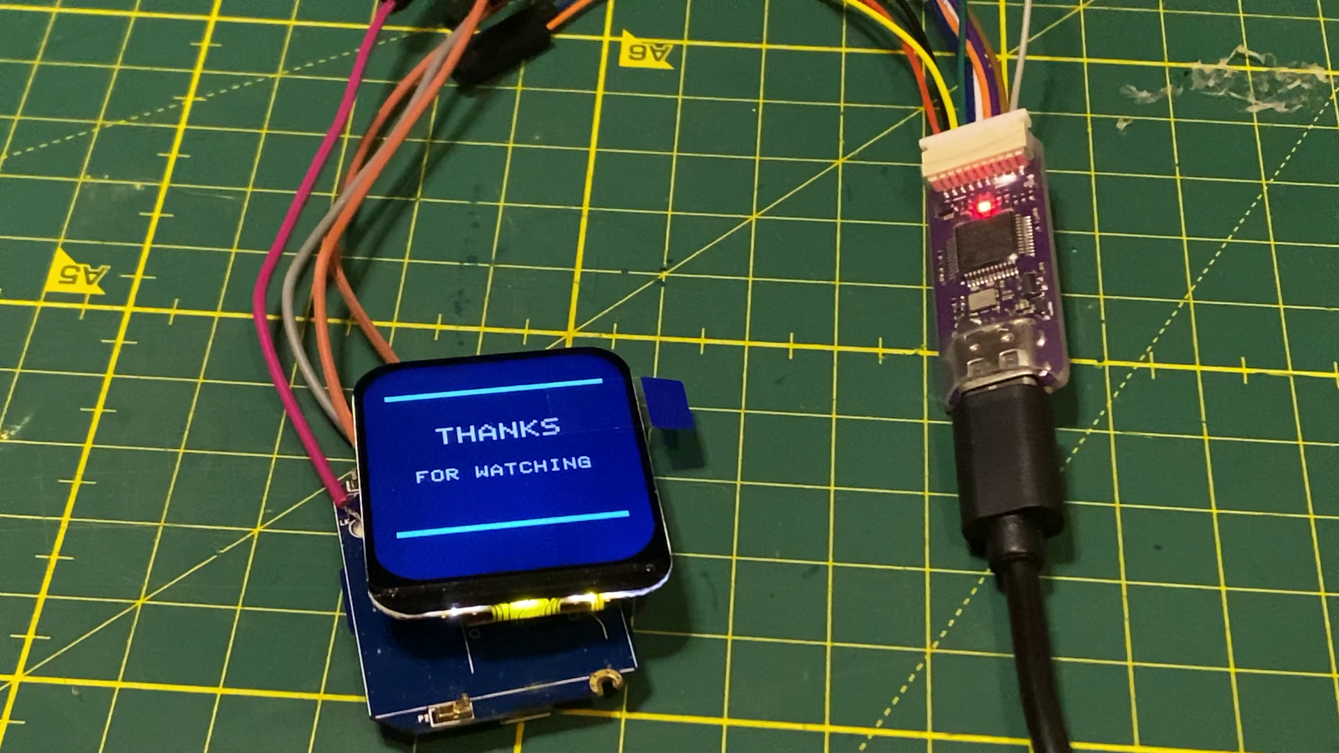
- Connect the larger 1.69" SPI LCD to the mapped display pins on the smartwatch PCB.
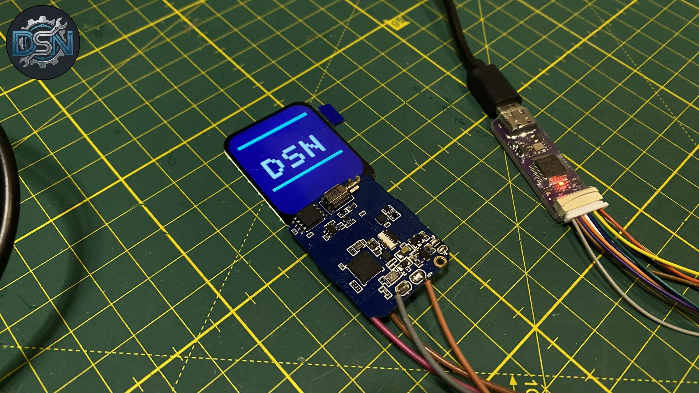
- Power the device and verify that the screen initializes properly with your custom UI/graphics.
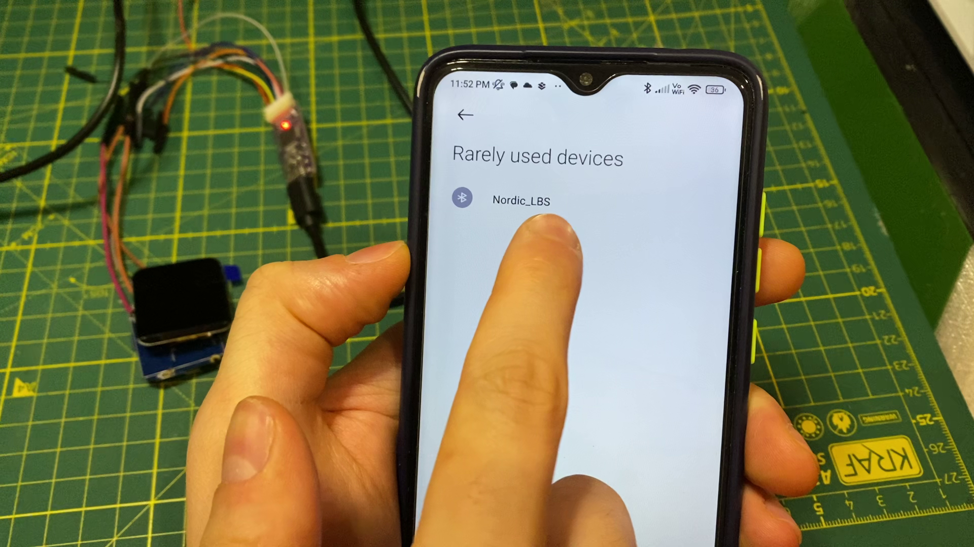
- Open a BLE scanner on your phone to confirm the smartwatch advertises over Bluetooth.