HackerBox 0128: Mesh Deck
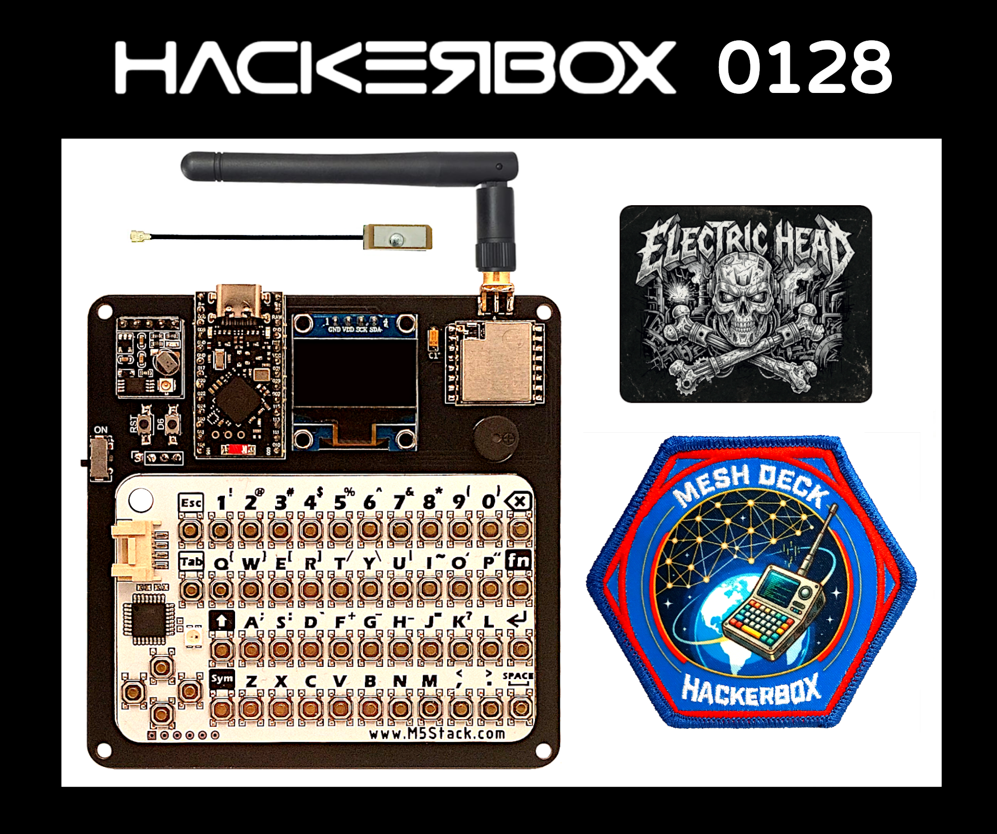
Welcome to HackerBox 0128. Assemble and experiment with an exclusive LoRa-based mesh communication platform leveraging a ProMicro nRF52840 development board, SX1262 LoRa module, ATGM336H GPS module, OLED Display, and CardKB mini keyboard. Explore Meshtastic - an open source, off-grid, decentralized mesh network built to run on affordable, low-power devices.
There is a wealth of information for current and prospective members in the HackerBoxes FAQ. Almost all of the non-technical support emails that we receive are already answered there, so we'd really appreciate it if you can take a few minutes to read the FAQ.
Supplies
This Instructable contains information for getting started with HackerBox 0128. The full box contents are listed on the product page for HackerBox 0128 where the box is also available for purchase while supplies last. If you would like to automatically receive a HackerBox like this right in your mailbox each month, you can subscribe at HackerBoxes.com and join the party. Subscription members save at least $15 every month and automatically receive each new HackerBox shipped immediately off the production line.
A soldering iron, solder, and basic assembly tools are generally needed to work on the monthly HackerBox. A computer for running software tools is also required. Have a look at the HackerBox Workshops for tools and supplies along with a wide array of introductory activities and experiments.
The most import thing you will need is a sense of adventure, hacker spirit, patience, and curiosity. Building and experimenting with electronics, while very rewarding, can be tricky, challenging, and even frustrating at times. The goal is progress, not perfection. When you persist and enjoy the adventure, a great deal of satisfaction can be derived from this hobby. Take each step slowly, mind the details, and don't be afraid to ask for help.
WEAR SAFETY GLASSES WHEN SOLDERING, WHEN TRIMMING WIRE LEADS, OR WHEN CUTTING, DRILLING, ETC.
Mesh Communications and Cyberdecks
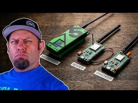
This video gives a nice overview of some common LoRa-based mesh communication solutions.
According to wikipedia, mesh network nodes connect directly, dynamically, and non-hierarchically to as many other nodes as possible. The nodes then cooperate with one another to efficiently route data. This lack of dependency on one node allows for every node to participate in the relay of information. Mesh networks dynamically self-organize and self-configure, which can reduce installation overhead. The ability to self-configure enables dynamic distribution of workloads, particularly in the event of node failure. This, in turn, contributes to fault-tolerance and reduced maintenance costs.
A deck, or cyberdeck, is a custom-built, portable computer, usually designed for a particular individualized purpose and often featuring a cyberpunk aesthetic. Decks are typically individually crafted and include a display and a keyboard. Cyberdeck terminology first appeared in William Gibson's 1984 novel Neuromancer.
"He’d operated on an almost permanent adrenaline high, a byproduct of youth and proficiency, jacked into a custom cyberspace deck that projected his disembodied consciousness into the consensual hallucination that was the matrix." - Gibson
ProMicro NRF52840 Development Board
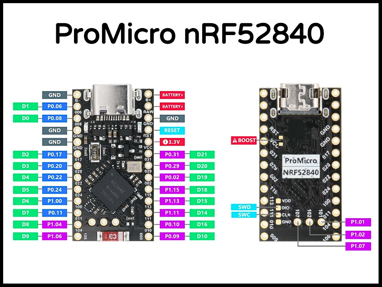
The nRF52840 SoC (Specs and Documentation from Nordic Semiconductor) features an ARM Cortex-M4F CPU clocked at 64MHz. It includes 1MB of flash memory and 256KB of RAM. The SoC supports multiple wireless protocols, including Bluetooth 5, Thread, Zigbee, ANT, and 2.4GHz. Peripherals include ADC, PWM, SPI, I2C, UART, USB, GPIO, etc. The nRF52840 also supports a variety of security functions, such as AES encryption, SHA-256 hashing and True Random Number Generator (TRNG).
The ProMicro nRF52840 development board is based on the Arduino Pro Micro layout and supports charging and discharging of a 3.7V lithium battery connected at the B+ and B- terminals. The charging rate can be set to 100mA or 300mA.
PRIOR TO SOLDERING - Apply initial power to the development board via USB
When first plugging in the ProMicro nRF52840, the red LED will blink slowly and the blue LED will blink quickly. More importantly, a USB storage device named NICENANO will appear on the attached computer. This demonstrates proper initialization of the board.
While we are not using either for this project, there is an Arduino Core as well as CircuitPython support for the ProMicro NRF52840. In a pinch, the ProMicro NRF52840 can be forced back into to bootloder mode by simply shorting the RST and GND pins together twice within half a second. The storage device named NICENANO will appear when the processes is performed correctly.
JUMPER TO BOOST THE BATTERY CHARGER
We suggest shorting the BOOST jumper on the bottom of the ProMicro nRF52840 to change the battery charge current from 100mA to 300mA. This is necessary when connecting a battery larger than 500mAh, which you may eventually wish to do. If instead, you already know that you will be using a battery that is smaller than 500mAh, then obviously do not short the BOOST jumper.
Notice that there is a circular hole in the Mesh Deck PCB immediately over the BOOST jumper. Through that hole, the jumper can be modified even after the nRF module is soldered into place. However, that can be a bit of a pain, so it is suggested to lock this decision in now and set the jumper while easy access to the bottom of the development board is still available.
Surface Mounted Components
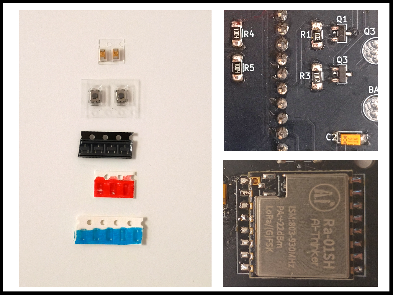
The HackerBox kit includes a small parts bag with the five "cut tape" SMD components shown in the image above along with a small six-pin slide switch. Install the five SMD components as explained here and hold the slide switch aside for use in a later step.
Two SMD 1M Resistors (White paper tape with RED marking)
These two resistors form a voltage divider through which the SoC measures the remaining charge level of the battery.
The two 1M resisters are marked "1004". These resistors are footprint size SMD-1206, which may seem small, but by normal SMD standards, 1206 components are gigantic. This package size is selected to be quite reasonable to cut, kit, and solder without special tools. Resistors are not polarized, so they can be placed in either orientation.
Flip the PCB with the back side facing up.
Solder the two resistors into positions R4 and R5.
Three N-Channel MOSFETs (Black plastic tape)
These MOSFETs serve to switch the ground line on three peripheral devices as originally presented here.
Q1 switches the GPS_EN signal between GPIO D5 on the nRF and the ground pin on the GPS module.
Q2 switches the buzzer signal between GPIO D9 on the nRF and the ground pin on the Piezo Buzzer.
Q3 switches an unused (extra) control signal between GPIO D1 on the nRF and the Q3 Pad exposed on the back of the PCB.
Each of these three transistors is a SI2312 N-Channel MOSFET in a SOT-23 package. This package type is pretty small, but with generous spacing between the three terminals, the device is quite reasonable to hand solder.
Three SMD 10K Resistors (White paper tape with BLUE marking)
These three resistors are pull-downs on the input signals to MOSTFETs Q1, Q2, and Q3.
The three 10K resisters are marked "1002". Solder the three resistors into positions R1, R2, and R3.
Two 10uF SMD Tantalum Capacitors (Clear plastic tape with yellow/orange components)
The two tantalum capacitors provide decoupling of 3.3V power rail at the Ra-01SH LoRa module and also at the CardKB mini keyboard.
Tantalum capacitors are polarized and must be properly oriented at positions C1 and C2. Each capacitor has a thick line marking across one edge on the top side of the component. That marked edge must be oriented closest to the C1 or C2 designator silkscreen which is also towards the inside of the three-sided rectangle outline around the device's PCB footprint. Solder C2 first and then flip the PCB over to the front side to solder C1.
Two Micro SMD Pushbutton Switches (Clear plastic tape holding silver components with round black buttons)
Also on the front side of the PCB, solder the two push buttons at the positions labeled RST and D6. The buttons are not polarized and may be soldered in either orientation. The RST button momentarily shorts the RESET pin of the nRF SoC to ground. The D6 button momentarily shorts the D6 GPIO pin of the nRF SoC to ground.
Ra-01SH LoRa Module
The Ra-01SH LoRa module (datasheet) was designed and developed by Anxinke Technology. The module is designed for ultra-long-distance spread-spectrum communication. Its radio chip, the SX1262, features SEMTECH's patented LoRa modulation technology for high sensitivity, power output of +22dBm, long transmission distances, and high reliability. This online tutorial covers the theory of operation for the SX1278 LoRa Modules.
Solder the Ra-01SH module as shown with the (unpopulated) IPEX antenna footprint oriented closest to the SMA antenna port on the main PCB. If you are new to soldering castellated modules, review this SparkFun tutorial.
Solder the Female SMA Edge Launch Connector
Be sure to position the center pin of the connector in the top side of the PCB. On the front side of the PCB, there is a solder pad for the center pin. However, there is no center pad on the back side of the PCB. The SMA connector has a bit of metal to it, so soldering it will probably take a couple more seconds than usual to build up enough heat to flow solder.
Modules and Through Hole Components
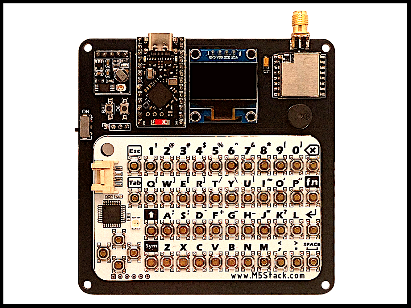
- Using the provided header pins, solder the ProMicro nRF52840 Development Board into place as shown with the USB-C port oriented towards the edge of the main PCB.
- Using the five pin header, solder the GPS module into place as shown with the IPEX connector facing out.
- Solder the OLED module into place as shown. It is helpful to use some "blue tack" or folded cardboard to hold the display board parallel to the main PCB while soldering.
- Solder the round buzzer into place as shown while matching the "+" pin to the marking on the PCB.
- Insert the slide switch as shown and solder it into place. This switch provides a power disconnect for the battery ground terminal.
Keyboard and Battery
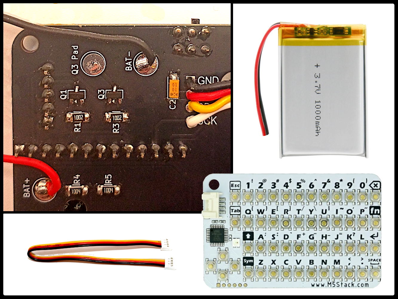
CardKB Mini Keyboard
Affix the keyboard to the front side of the main PCB as shown. Some hot glue, adhesive, double sided tape, or even just a loop of packing tape can do the trick.
Plug one end of the provided wiring harness into the keyboard.
Cut the connector from the other end and strip a couple millimeters of insulation from each wire.
Lace the cut end of the wiring harness through the round hole at the top of the keyboard.
Insert each wire into the BACK SIDE of the main PCB as shown. Solder the wire tips from the front of the PCB.
It is suggested to insert the keyboard wires into the back of the PCB since the build is easier to tighten up later with any slack in the wires routed behind the scenes.
Tighten Up The Keyboard Wiring (optional)
This optional process can be carried out later, or never, as you choose...
Unplug the wiring harness connector from the keyboard.
Remove the four-pin SMT connector from the keyboard. (video)
Cut the connector from the wiring harness.
Optionally cut the wires to remove most of the slack in the wires.
Strip a couple millimeters of insulation from each wire.
Solder the stripped ends of the wires onto the pads where the the four-pin SMT connector was removed.
Push any remaining slack through the hole towards the back side of the PCB.
LiPo Battery (optional)
A 3.7V battery can be connected to the BAT+ and BAT- pads on the back of the PCB as shown.
Recall from earlier discussion, the BOOST jumper on the back side of the ProMicro nRF52840 Development Board should be shorted closed when a battery larger than 500mAh is used.
Meshtastic
Meshtastic
An open source, off-grid, decentralized mesh network built to run on affordable, low-power devices. No cell towers. No internet. Just pure peer-to-peer connectivity. (meshtastic.org)
Programming Meshtastic onto the Mesh Deck
Be sure to connect the SMA antenna before flashing firmware onto the Mesh Deck. Powering up the LoRa module without an RF load (antenna) may cause damage to the module.
Visit this page with resources to update the nRF52 bootloader.
Grab the bootloader package called "Generic Meshtastic 6.1.1 for DIY".
Drag and drop that UF2 file onto the NICENANO volume.
The nRF52 will automatically update the bootloader and reset.
After the reset, the latest bootloader version is running.
Proceed with flashing Meshtastic.
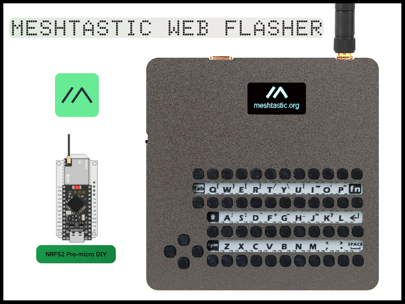
Select Target Device > nRF52840 > NRF52 Pro-micro DIY
Once the firmware is flashed, open the serial monitor using that same webpage.
3D Printing an Enclosure
The enclosure for the FakeDeck could be easily modified to fit the Mesh Deck. The "buttons in one piece" file can be used without modification since the rows of buttons are sized exactly to the size and spacing of the CardKB Mini Keyboard.
Member dbuckl shared this nice example on Thingverse.
Man-Amplifiers
)
"Clock DVA's [1991 Album] Man-Amplified builds on cyberpunk themes with precise, rhythmic electronic music. The album blends techno, ambient, and industrial influences to create a conceptual journey into technology's impact on humanity. Adi Newton's intricate sound design and thematic depth make it a compelling exploration of the future and man's relationship with machines." - DeBaser
MAN-AMPLIFIERS
The first users of tools were not men (a fact appreciated only recently) but pre-human anthropoids. The old idea that man invented tools is misleading, more accurately tools invented man - so began the symbiosis. The physicist J.D. Beral's book published in 1929 called "The World, The Flesh and The Devil" decided that the numerous limitations of the human body could be overcome only by the use of mechanical attachments or substitutes until eventually all that might be left of mans original organic body would be the brain. The word "Cyborg" (cybernet organism) devised by Dr. Manfred Clynes and Nathan Kline, define a cyborg as "An exogenously extended organisational complex, functioning as a homeostatic system". Along with other computer experts Dr. Clynes believes that intelligence need not be confined to the DNA structure. He also believes that life is more a matter of relationships and organisation than of material. Clynes points out an understanding of the nature of our thoughts in terms of their mathematical, electronic and time-space identities which will permit us to communicate better than we do at the present time, we may find new shapes and discover means of utilising them to communicate in entirely new ways, ways that cannot presently be imagined. A.C. Clarke sees the outcome of the future of the man machine as eventually a machine based evolution. Whatever the key may be to longevity, man continues to amplify himself ever onwards in his desire to expand the nature of the self towards new points, new levels, that currently cannot be accurately predicted. The man amplifier is presently increasing its volume.
Fractalize
We hope you are enjoying this month's HackerBox adventures into electronics, computer technology, and hacker culture. We aim to curate a challenging and rewarding experience of learning through experimentation and exploration. Thank you for joining us on this journey.
Reach out and share your success in the comments below. Email support@hackerboxes.com anytime with questions or whenever you need some help.
Hungry for more? Surf over to HackerBoxes.com and join us as a monthly HackerBox subscription member. You'll get a cool box of hackable gear delivered right to your mailbox every month and you'll enjoy a generous member discount.
Please consider sharing this free Instructable with others who may be interested in learning about these subjects. Word of mouth advertising is the greatest compliment that we can receive. We sincerely appreciate your support.